EP1594701B1 - Tintenstrahlkopf - Google Patents
Tintenstrahlkopf Download PDFInfo
- Publication number
- EP1594701B1 EP1594701B1 EP04706059A EP04706059A EP1594701B1 EP 1594701 B1 EP1594701 B1 EP 1594701B1 EP 04706059 A EP04706059 A EP 04706059A EP 04706059 A EP04706059 A EP 04706059A EP 1594701 B1 EP1594701 B1 EP 1594701B1
- Authority
- EP
- European Patent Office
- Prior art keywords
- fluid ejection
- orifices
- channel
- group
- fluid
- Prior art date
- Legal status (The legal status is an assumption and is not a legal conclusion. Google has not performed a legal analysis and makes no representation as to the accuracy of the status listed.)
- Expired - Lifetime
Links
- 239000012530 fluid Substances 0.000 title claims abstract description 290
- 238000012864 cross contamination Methods 0.000 claims abstract description 17
- 239000000758 substrate Substances 0.000 claims abstract description 17
- 238000004140 cleaning Methods 0.000 claims description 14
- 238000004519 manufacturing process Methods 0.000 claims description 10
- 239000002699 waste material Substances 0.000 claims description 2
- 239000010410 layer Substances 0.000 description 36
- 230000004888 barrier function Effects 0.000 description 24
- 239000011241 protective layer Substances 0.000 description 15
- 239000000976 ink Substances 0.000 description 10
- 238000007639 printing Methods 0.000 description 9
- 239000000463 material Substances 0.000 description 5
- 230000008901 benefit Effects 0.000 description 4
- 238000011109 contamination Methods 0.000 description 4
- 238000000034 method Methods 0.000 description 4
- 230000007480 spreading Effects 0.000 description 4
- 238000003892 spreading Methods 0.000 description 4
- 238000010304 firing Methods 0.000 description 3
- 230000015572 biosynthetic process Effects 0.000 description 2
- 239000003086 colorant Substances 0.000 description 2
- 238000005516 engineering process Methods 0.000 description 2
- 230000007246 mechanism Effects 0.000 description 2
- 239000000203 mixture Substances 0.000 description 2
- 229920002120 photoresistant polymer Polymers 0.000 description 2
- 230000008569 process Effects 0.000 description 2
- 230000001681 protective effect Effects 0.000 description 2
- 239000004593 Epoxy Substances 0.000 description 1
- 230000000740 bleeding effect Effects 0.000 description 1
- -1 but not limited to Substances 0.000 description 1
- 239000000356 contaminant Substances 0.000 description 1
- 238000005530 etching Methods 0.000 description 1
- 230000000873 masking effect Effects 0.000 description 1
- 238000000926 separation method Methods 0.000 description 1
- 239000000126 substance Substances 0.000 description 1
- 230000001960 triggered effect Effects 0.000 description 1
Images


Classifications
-
- B—PERFORMING OPERATIONS; TRANSPORTING
- B41—PRINTING; LINING MACHINES; TYPEWRITERS; STAMPS
- B41J—TYPEWRITERS; SELECTIVE PRINTING MECHANISMS, i.e. MECHANISMS PRINTING OTHERWISE THAN FROM A FORME; CORRECTION OF TYPOGRAPHICAL ERRORS
- B41J2/00—Typewriters or selective printing mechanisms characterised by the printing or marking process for which they are designed
- B41J2/005—Typewriters or selective printing mechanisms characterised by the printing or marking process for which they are designed characterised by bringing liquid or particles selectively into contact with a printing material
- B41J2/01—Ink jet
- B41J2/135—Nozzles
- B41J2/14—Structure thereof only for on-demand ink jet heads
-
- B—PERFORMING OPERATIONS; TRANSPORTING
- B41—PRINTING; LINING MACHINES; TYPEWRITERS; STAMPS
- B41J—TYPEWRITERS; SELECTIVE PRINTING MECHANISMS, i.e. MECHANISMS PRINTING OTHERWISE THAN FROM A FORME; CORRECTION OF TYPOGRAPHICAL ERRORS
- B41J2/00—Typewriters or selective printing mechanisms characterised by the printing or marking process for which they are designed
- B41J2/005—Typewriters or selective printing mechanisms characterised by the printing or marking process for which they are designed characterised by bringing liquid or particles selectively into contact with a printing material
- B41J2/01—Ink jet
- B41J2/135—Nozzles
- B41J2/14—Structure thereof only for on-demand ink jet heads
- B41J2/1433—Structure of nozzle plates
-
- B—PERFORMING OPERATIONS; TRANSPORTING
- B41—PRINTING; LINING MACHINES; TYPEWRITERS; STAMPS
- B41J—TYPEWRITERS; SELECTIVE PRINTING MECHANISMS, i.e. MECHANISMS PRINTING OTHERWISE THAN FROM A FORME; CORRECTION OF TYPOGRAPHICAL ERRORS
- B41J2/00—Typewriters or selective printing mechanisms characterised by the printing or marking process for which they are designed
- B41J2/005—Typewriters or selective printing mechanisms characterised by the printing or marking process for which they are designed characterised by bringing liquid or particles selectively into contact with a printing material
- B41J2/01—Ink jet
- B41J2/135—Nozzles
- B41J2/165—Prevention or detection of nozzle clogging, e.g. cleaning, capping or moistening for nozzles
-
- B—PERFORMING OPERATIONS; TRANSPORTING
- B41—PRINTING; LINING MACHINES; TYPEWRITERS; STAMPS
- B41J—TYPEWRITERS; SELECTIVE PRINTING MECHANISMS, i.e. MECHANISMS PRINTING OTHERWISE THAN FROM A FORME; CORRECTION OF TYPOGRAPHICAL ERRORS
- B41J2/00—Typewriters or selective printing mechanisms characterised by the printing or marking process for which they are designed
- B41J2/005—Typewriters or selective printing mechanisms characterised by the printing or marking process for which they are designed characterised by bringing liquid or particles selectively into contact with a printing material
- B41J2/01—Ink jet
- B41J2/135—Nozzles
- B41J2/165—Prevention or detection of nozzle clogging, e.g. cleaning, capping or moistening for nozzles
- B41J2/16502—Printhead constructions to prevent nozzle clogging or facilitate nozzle cleaning
Definitions
- Fluid ejection devices may find uses in a variety of different technologies. For example, some printing devices, such as printers, copiers and fax machines, print by ejecting tiny droplets of a printing fluid from an array of fluid ejection orifices onto the printing medium.
- the fluid ejection mechanisms are typically formed on a fluid ejection head that is movably coupled to the body of the printing device. Careful control of such factors as the individual fluid ejection mechanisms, the movement of the fluid ejection head across the printing medium, and the movement of the medium through the device allows a desired image to be formed on the medium.
- United States Patent No. 4599627 discloses an ink printer having two separate ejection heads ejecting two different fluids.
- Some other fluid ejection devices may be configured to eject a plurality of different fluids, such as different ink colors and/or compositions, from a single fluid ejection head.
- each individual fluid is typically ejected from a group of closely spaced fluid ejection orifices, and the different groups of orifices for the different fluids are spaced a greater distance apart.
- the use of such a fluid ejection head may offer several advantages over the use of separate fluid ejection heads for each different fluid. For example, a single fluid ejection head is typically less expensive than multiple fluid ejection heads, and also may use less space than multiple fluid ejection heads for a fluid ejection device of a comparable size.
- a fluid ejection head may also present various problems. For example, when printing with (or otherwise using) any fluid ejection device, small droplets of fluids may end up on the surface of the fluid ejection head surrounding the orifice from which it was ejected, instead of onto the intended medium. Where the fluid ejection head is configured to eject multiple fluids, these stray droplets may contaminate an adjacent fluid ejection orifice for a different fluid, and thus cause undesirable mixing of fluids.
- many fluid ejection devices include a wiper structure to clean the fluid ejection head of stray fluid droplets.
- the wiper structure wipes across the fluid ejection head surface, pushing a wave of fluid or fluids in front of it.
- the wiper structure may mix the different fluids, and thus may cause the contamination of fluid ejection orifices of one type of fluid with other fluids.
- fluids commonly used with fluid ejection devices are configured to react with other fluids ejected from the same device. Inks with this property are referred to generally as "reactive inks.” If one of the reacting fluids is not an ink, it may be referred to as a "fixer fluid.” Where two reactive fluids are ejected from the same fluid ejection device, the fluids may be configured to immediately harden at the boundary where the drop of one fluid meets a drop of the other fluid to prevent color mixing and/or bleeding on a fluid-receiving medium.
- the fluids may harden and clog the ejection orifice.
- the hardened fluids may then be difficult to remove by "spitting", or firing fluids through the orifice at a cleaning station.
- US Patent No. 6,132,028 discloses an orifice plate for a thermal ink jet print head having at least two groups of ink orifice apertures.
- the orifices are disposed in an orifice layer which is disposed on top of a substrate layer.
- the orifice plate has a major surface and an elevated region surrounding each of the orifices.
- the print head has a wiper passing over the orifices. The wiper is configured to be positioned so that it contacts the elevated surface to remove droplets on the elevated surface without contacting lower contaminants on the major surface.
- Japanese Patent No. 07017062 discloses an ink jet print head having three groups of orifices for providing different colors of ink.
- the orifices are disposed in an orifice layer which is disposed on top of a substrate layer.
- the print head has an elongate groove between each two adjacent groups of orifices to prevent ink contamination.
- the present invention provides a fluid ejection device according to claim 1 and a method of making a fluid ejection device according to claim 12.
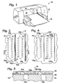
- Fluid ejection device 10 takes the form of a desktop printer, and includes a body 12, and a fluid ejection cartridge 14 operatively coupled to the body. Fluid ejection cartridge 14 is configured to deposit a fluid onto a medium 16 positioned adjacent to the cartridge via a fluid ejection head 18. Control circuitry in fluid ejection device 10 controls the movement of fluid ejection cartridge 14 across medium 16, the movement of the medium under the fluid ejection cartridge, and the firing of fluid from the individual fluid ejection orifices on the fluid ejection cartridge.
- a fluid ejection device according to the present invention may be used in any number of different applications.
- a fluid ejection device may take the form of any other suitable type of printing device, such as a copier or a facsimile machine, and may have any other desired size, large- or small-format.
- Fluid ejection head 18 includes a first fluid feed slot 20a for delivering a first fluid to the fluid ejection head, and a second fluid feed slot 20b for delivering a second fluid to the fluid ejection head. Only two fluid feed slots are shown for clarity. However, it will be appreciated that a fluid ejection head according to the present invention may have any desired number of fluid feed slots, and generally at least one for each type of fluid ejected. For example, a six-color fluid ejection head may have six or more fluid feed slots.
- Fluid ejection head 18 also includes at least one fluid ejection orifice for each fluid feed slot 20 a , b .
- fluid ejection head 18 includes two separate columns of orifices, indicated at 21 and 21', for each fluid feed slot.
- the orifices corresponding to fluid feed slot 20 a are shown at 22 a
- the orifices corresponding to fluid feed slot 20 b are shown at 22 b .
- the use of columns of orifices 22 a and 22 b to eject fluids helps to decrease the width of the fluid ejection head or carriage as fluid ejection head 18 is passed across medium 16, and thus helps to decrease the time to print a desired image.
- each fluid feed slot 20 a and 20 b of the depicted embodiment has two associated columns of fluid ejection orifices, it will be appreciated that each fluid feed slot may also have only a single column of associated fluid ejection orifices, or more than two columns of orifices.
- fluid feed slots 20 a and 20 b very close together, for example, on the order of 1.2-1.4 millimeters apart. This is advantageous, as it helps to decrease the size of fluid ejection head 18, and thus the manufacturing cost of the fluid ejection head. However, this also places the orifices 22 a that are most closely adjacent to the orifices 22 b a distance of approximately one millimeter from orifices 22 b .
- fluid ejection head 18 also includes a cross-contamination barrier disposed between fluid ejection orifices 22 a and 22 b .
- Fig. 2 shows, generally at 30, a first exemplary embodiment of a suitable cross-contamination barrier
- Fig. 3 shows a cross-sectional view of the barrier.
- Barrier 30 includes a pair of trenches or channels 32 a , 32 b configured to form a sufficient break in the surface of fluid ejection head 18 to prevent puddles of fluid from fluid ejection orifices 22 a from spreading far enough to contaminate fluid ejection orifices 22 b , and vice versa.
- channels 32 a and 32 b are also configured to prevent the wave of fluid pushed in front of a wiper in a wiping station from spreading to adjacent fluid ejection orifices. This helps to prevent different fluids from being mixed by the wiper, and thus helps to prevent cross-contamination of orifices 22 a and 22 b by the wiper. While the embodiment of Figs. 2-3 has two generally parallel channels 32 a and 32 b , other embodiments of the cross-contamination barrier may have three, four, or more parallel channels.
- Channels 32 a and 32 b may have any suitable structure.
- the depicted fluid ejection head 18 includes a substrate layer 34, an intermediate protective layer 36, and an orifice layer 38.
- the surface of the substrate layer 34 typically includes circuit structures (not shown) configured to cause the ejection of fluid from a fluid ejection orifice when triggered by off-substrate circuitry, while orifice layer includes the structures that form the fluid ejection orifices and corresponding firing chambers.
- Fluid feed slots 20 a and 20 b are formed in substrate layer, while fluid ejection orifices 22 a and 22 b extend through protective layer 36 and orifice layer 38.
- Channels 32 a and 32 b of the depicted embodiment are formed in orifice layer 38, and extend completely through the orifice layer to protective layer 36. While channels 32 a and 32 b of the depicted embodiment extend through the entire thickness of orifice layer 38, it will be appreciated that the channels may also extend only partially through the orifice layer.
- protective layer 36 is configured to protect the surface of substrate layer 34 and the circuit structures thereon from any reactive and/or corrosive fluids that may enter channels 32 a and 32 b .
- Protective layer 36 may be made from any suitable material, including, but not limited to, epoxy-based photoresists such as an SU-8 resist, available from MicroChem, Inc. or Sotec Microsystems.
- protective layer 36 may have any suitable thickness. Where protective layer 36 is formed from SU-8, a relatively thin layer, on the order of approximately two to four microns, may be used to form protective layer 36. This may be advantageous, as a relatively thin layer of protective material may be less expensive to fabricate than a thicker protective layer. It will be appreciated that protective layer 36 may be omitted entirely if desired.
- the circuit structures on the surface of substrate layer 34 may include other protective means as known to those of skill in the art.
- Channels 32 a and 32 b may be formed at any suitable location between fluid ejection orifices 22 a and 22 b .
- the halfway point between channels 32 a and 32 b is positioned approximately halfway between fluid feed slot 20 a and fluid feed slot 20 b , although the two channels may be centered at another location if desired.
- channels 32 a and 32 b are centered substantially intermediate fluid ejection orifices 22 a and 22 b , as placing the center channels closer to the midway point between orifices 22 a and 22 b allows a larger puddle to form on either side of the channels before the puddle encounters the channels. This may make the puddle less likely to fill, and thus bridge, the channel.
- Channels 32 a and 32 b may be separated by any suitable distance.
- channels 32 a and 32 b may be separated by a distance in the range of 25-100 microns, and more typically by a distance of approximately 50 microns.
- channels 32 a and 32 b may have any suitable widths. Suitable widths include, but are not limited to, those in the range of approximately 20-80 microns. More typically, channels 32 a and 32 b have widths of approximately 50 microns.
- Channels 32 a and 32 b may also have any suitable length.
- channels 32 a and 32 b are configured to extend at least as far as the length of columns 21 and 21' of fluid ejection orifices so that no straight path exists between any of fluid ejection orifices 22 a and any of fluid ejection orifices 22 b .
- channels 32 a and 32 b may be configured to extend beyond the ends of columns 21 and 21' of fluid ejection orifices to add additional protection against cross-contamination.
- channels 32 a and 32 b may extend any desired distance beyond the ends of columns 21 and 21' of fluid ejection orifices.
- Suitable distances include, but are not limited to, approximately 300-500 microns beyond each end of columns 21 and 21' of fluid ejection orifices.
- columns 21 and 21' of fluid ejection orifices may include some orifices that are not fluidically connected to fluid feed slots 20 a or 20 b .
- channels 32 a and 32 b may have a length that extends as far as (or beyond) the last fluidically connected fluid ejection orifice.
- channels 32 a and 32 b may have any suitable depth.
- channels 32 a and 32 b may extend only partway through orifice layer 38, or all the way through orifice layer 38.
- Typical depths of channels 32 a and 32 b include, but are not limited to, depths ranging from approximately 10 microns to the entire depth of the orifice layer, which is typically 20-100 microns thick.
- Channels 32 a and 32 b may be formed in any suitable manner.
- channels 32 a and 32 b are formed as fluid ejection orifices 22 a and 22 b are formed. In these embodiments, the formation of channels 32 a and 32 b may not significantly increase the cost and/or difficulty of the overall fluid ejection head manufacturing process.
- the method or methods used to form channels 32 a and 32 b typically depend upon the material and/or materials from which orifice layer 38 is formed.
- a photoresist such as an SU-8 resist, may be used to form orifice layer 38..
- Fig. 4 shows, generally at 130, a second alternative embodiment of a cross-contamination barrier according to the present invention.
- barrier 130 includes a single continuous channel 132.
- Channel 130 may have any suitable dimensions, including, but not limited to, those described above for each of channels 32 a and 32 b of the embodiment of Figs. 2-3 .
- the depicted channel 132 runs beyond the length of columns 121 and 121' of fluid ejection orifices, and is situated approximately halfway between fluid feed slots 120 a and 120 b .
- channel 132 may have any suitable width. Suitable widths include, but are not limited to, widths between approximately fifty to five hundred microns (or approximately 5-50% of the spacing between fluid feed slots 120 a and 120 b) .
- Fig. 5 shows, generally at 230, a third alternative embodiment of a cross-contamination barrier according to the present invention.
- Barrier 230 includes a first channel 232 a surrounding fluid feed slot 220 a and fluid ejection orifices 222 a in a closed loop, and a second channel 232 b surrounding fluid feed slot 220 b and fluid ejection orifices 222 b in a closed loop.
- the details of barrier 230 are described herein in terms of first channel 232 a . However, it will be appreciated that the description is equally applicable to second channel 232 b .
- channel 232 a is configured to surround fluid ejection orifices 222 a substantially completely to help to prevent fluid puddles from spreading in any direction from the fluid ejection orifices.
- Channel 232 a may have any suitable dimensions, and may be formed in any suitable location on fluid ejection head 18.
- channel 232 a is positioned 200-500 microns from the nearest fluid ejection orifices 222 a along the long side or dimension 234 of the channel, and 100-500 microns from the nearest fluidically-connected fluid ejection orifice along the short side or dimension 236 of the channel, although channel 232 a may also be separated from fluid ejection orifices 222 a by distances outside of these ranges.
- Channel 232 a may also have any suitable width.
- Channel 232 may have a width between approximately 20 and 200 microns, or between approximately 50-100 microns. While the depicted channels 232 a and 232 b completely surround the respective fluid ejection orifices, the channels may also only partially surround the fluid ejection orifices if desired.
- Fig. 6 shows, generally at 330, another embodiment of a suitable cross-contamination barrier according to the present invention formed between fluid feed slots 320 a and 320 b .
- barrier 330 includes a plurality of shorter channels 332 arranged in a grate-like arrangement.
- the individual shorter channels are arranged into two columns of channels, indicated at 334 a and 334 b .
- the individual channels of channel column 334 a are offset along the direction of the length of the channel columns with respect to the individual channels of channel column 334 b .
- the offset configuration helps to ensure that no direct path exists between fluid ejection orifices 322 a and 322 b of slots 320 a and 320 b , respectively.
- the individual channels 332 of channel columns 334 a and 334 b may have any suitable dimensions. Suitable lengths for channels 332 include, but are not limited to, lengths of 700-1100 microns. Furthermore, each of channel columns 334 a and 334 b may have any suitable number of individual channels. For example, where the fluid ejection head has a height (along the long dimension of the fluid feed slots and fluid ejection orifice channels) of 8500 microns, and the individual channels 332 each have a length of 900 microns, one channel column may have seven individual channels, and the other channel column may have six individual channels.
- Figs. 7 and 8 show, generally at 430, another embodiment of a cross-contamination barrier according to the present invention.
- barrier 430 elevates the fluid ejection orifices above a surrounding waste-receiving portion 432 of the fluid ejection head on plateau-like structures, indicated at 436 a and 436 b .
- waste-receiving portion 432 may be as wide as approximately one millimeter, or even wider.
- the fluid ejection heads of Figs. 5 and 7 are formed in a substantially similar manner.
- the barriers 230, 430 are formed by masking the resist layer and exposing the resist layer to form the desired shapes.
- the difference in formation is the use of different resist masks.
- One type of resist mask may be used to form the closed loop configuration of Fig. 5 and its orifices, while a second type of resist mask may be used to form the waste receiving portion of Fig. 7 and its orifices.
- the mask used in Fig. 7 allows the removal of more resist than the mask of Fig. 5 .
- waste-receiving portion 432 may extend the full thickness of orifice layer 438 (to the intermediate protective layer 435), or may extend only partially through the thickness of the orifice layer.
- Wiper structure includes orifice wipers 442 a and 442 b configured to wipe over fluid ejection orifices 422 a and 422 b , respectively, and waste-receiving portion wipers 444 configured to clean waste-receiving portion 432.
- Orifice wipers 442 a and 442 b are configured to push fluids off of plateaus 436 a and 436 b and into adjacent waste-receiving portion 432.
- Orifice wipers 442 a and 442 b may have any suitable structure.
- each orifice wiper 442 a and 442 b may have a wiping structure with a diagonal orientation relative to the direction of wiper movement across plateaus 436 a and 436 b . This structure may push fluids into the waste-receiving portion 432 adjacent the lagging edge of the wiper.
- orifice wipers 442 a and 442 b may have a chevron-shaped wiping structure.
- orifice wipers 442 a and 442 b push fluids toward channels 432 on either side of plateaus 436 a and 436 b .
- Waste-receiving portion wiper 444 is positioned between (and on either side of) plateaus 436 a and 436 b , and is configured to extend into waste-receiving portion 432 to wipe fluids from the waste-receiving portion.
- Waste-receiving portion wiper 444 may have any suitable configuration.
- waste-receiving portion wiper 444 may have a concave structure to move fluids away from the sides of plateaus 436 a and 436 b as the orifice wiper is moved across the fluid ejection head.
- waste-receiving portion wiper 444 may have a generally straight shape, and may be oriented generally perpendicular to the direction in which wiper 440 is moved across the surface of the fluid ejection head.
- orifice wipers 442 a and 442 b may be configured to wipe across the surface independently of waste-receiving portion wiper 444. In these embodiments, orifice wipers 442 a and 442 b may be configured to wipe across plateaus 436 a and 436 b at a different period and/or frequency as waste-receiving portion wiper 444 across waste-receiving portion 432.
- orifice wipers 442 a and 442 b may be configured to wipe across plateaus 436 a and 436 b after two minutes of fluid ejection head use, while waste-receiving portion wiper 444 may be configured to clean waste-receiving portion 432 less frequently, for example, every twenty minutes.
- orifice wipers 442 a and 442 b may be pressed against a fluid ejection head at different pressures during a wiping process (or processes), and may be made from different materials.
- FIG. 9 shows a sectional view of an alternative embodiment of the fluid ejection head of Fig. 7 , with the protective layer 435 omitted.
- waste-receiving portion 432 extends to substrate layer 434.
- Figs. 10 and 11 show a fluid ejection head having another embodiment of a cross-contamination barrier 530 according to the present invention.
- barrier 530 elevates fluid ejection orifices 522 a and 522 b above a surrounding waste-receiving portion 532 of the fluid ejection head on plateau-like structures, indicated at 536 a and 536 b .
- barrier 530 also includes a wall 540 running the length of waste-receiving portion 532, dividing waste-receiving portion 532 into a first waste-receiving portion 532 a and a second waste-receiving portion 532 b .
- wall 540 may help to serve as a further barrier against cross-contamination, and also may allow fabrication of barrier 530 with less etching of orifice layer 538. It will be appreciated that a suitable wiper structure (not shown) with a waste-receiving portion wiper for each of first and second waste-receiving portions 538 a and 538 b is employed to clean the barrier structure of the embodiment of Figs. 10 and 11 .
- the channel structures disclosed herein may offer additional benefits besides helping to prevent cross-contamination of fluids.
- the wiping force from the fluid ejection head wiping structures is distributed across the entire fluid ejection head.
- the wiping force may be more concentrated on the fluid ejection orifices, which may lead to a more efficient and complete wipe.
- the channels may provide some amount of stress relief in the orifice layer of the fluid ejection head, and thus may help to prevent damage caused by thermal expansion differences between the substrate layer, the intermediate protective layer, and the orifice layer.
Landscapes
- Ink Jet (AREA)
- Particle Formation And Scattering Control In Inkjet Printers (AREA)
- Nozzles (AREA)
- Coating Apparatus (AREA)
Claims (16)
- Fluidausstoßeinrichtung mit einem Fluidausstoßkopf (18) und einer Reinigungsvorrichtung (440), wobei der Fluidausstoßkopf eine Düsenschicht (38, 438) aufweist, die an der Oberseite einer Substratschicht (34, 434) angeordnet ist,
wobei der Fluidausstoßkopf umfasst:eine erste Gruppe von Fluidausstoßdüsen (22a, 422a) und eine zweite Gruppe von Fluidausstoßdüsen (22b, 422b), die in der Düsenschicht (38, 438) ausgebildet sind,wobei die erste Gruppe von Fluidausstoßdüsen (22a, 422a) und die zweite Gruppe von Fluidausstoßdüsen (22b, 422b) so konfiguriert sind, dass sie zwei unterschiedliche Fluide ausstoßen; undeinen langgestreckten Kanal (32a, 432), der in der Düsenschicht ausgebildet ist, wobei der Kanal (32a, 32b, 432) zwischen der ersten Gruppe von Fluidausstoßdüsen (22a, 422a) und der zweiten Gruppe von Fluidausstoßdüsen (22b, 422b) so positioniert ist,dass eine gegenseitige Verunreinigung der von der ersten Gruppe von Fluidausstoßdüsen (22a, 422a) und der von der zweiten Gruppe von Fluidausstoßdüsen (22b, 422b) ausgestoßenen Fluide verhindert wird, dadurch gekennzeichnet, dass die Reinigungsvorrichtung (440) eine Reinigungsstruktur (444) aufweist, die dazu konfiguriert ist, sich in den Kanal (32a, 32b, 432) zu erstrecken, um Fluid aus dem Kanal (32a, 32b, 432) zu wischen. - Fluidausstoßeinrichtung nach Anspruch 1, wobei der Kanal (32a) ein erster Kanal ist und ferner mit einem zweiten Kanal (32b), der zum ersten Kanal (32a) parallel verläuft.
- Fluidausstoßeinrichtung nach Anspruch 2, wobei die erste Gruppe von Fluidausstoßdüsen (22a) in einer ersten Spalte (21) aus Fluidausstoßdüsen angeordnet ist und wobei die zweite Gruppe von Fluidausstoßdüsen (22b) in einer zweiten Spalte (21) von Fluidausstoßdüsen angeordnet ist, wobei die erste und die zweite Spalte der Fluidausstoßdüsen jeweils eine Länge haben und wobei der erste und der zweite Kanal (32a, b) jeweils wenigstens über die Länge der ersten und der zweiten Spalte (21) der Fluidausstoßdüsen verläuft.
- Fluidausstoßeinrichtung nach Anspruch 2, wobei der erste Kanal (332) einer von einer Vielzahl von Kanälen (332) in einer ersten Kanalspalte (334a) ist und wobei der zweite Kanal (332) einer (332) von einer Vielzahl von Kanälen (332) in einer zweiten Kanalspalte (334b) ist, und wobei jeder Kanal (332) in der ersten Kanalspalte (334a) in Bezug auf jeden Kanal (332) in der zweiten Kanalspalte (334b) in Längsrichtung versetzt ist.
- Fluidausstoßeinrichtung nach Anspruch 1, wobei der Kanal (232a) sich in einer engen Schleife um die erste Gruppe der Fluidausstoßdüsen (222b) erstreckt.
- Fluidausstoßeinrichtung nach Anspruch 1, wobei der Kanal einen Graben (32a) umfasst.
- Fluidausstoßeinrichtung nach Anspruch 2, wobei die Kanäle (32a, b) Entsorgungskanäle definieren und an dem Fluidausstoßkopf (18) zwischen der ersten Gruppe von Düsen (22a) und der zweiten Gruppe von Düsen (22b) bei einer Position angeordnet sind, die im Wesentlichen zwischen der ersten Gruppe von Düsen (22a) und der zweiten Gruppe von Düsen (22b) liegt.
- Fluidausstoßeinrichtung nach einem der vorangehenden Ansprüche, wobei die Reinigungsstruktur (444) eine konkave Struktur hat, um Fluid aus dem Kanal (32a, 32b, 432) wegzubewegen.
- Fluidausstoßeinrichtung nach einem der Ansprüche 1 bis 7, wobei die Reinigungsstruktur (444) eine im Wesentlichen gerade Form hat und im Wesentlichen senkrecht zu der Richtung ausgerichtet ist, in der sich die Reinigungsvorrichtung (440) bewegt.
- Fluidausstoßeinrichtung nach einem der vorangehenden Ansprüche, mit ferner einer ersten Düsenreinigungsstruktur (442a), die zum Wischen über einen ersten Düsenteil (436a) des Fluidausstoßkopfes konfiguriert ist, wobei die erste Gruppe von Fluidausstoßdüsen (22a, 422a) in dem ersten Düsenteil angeordnet ist.
- Fluidausstoßeinrichtung nach Anspruch 10, mit ferner einer zweiten Düsenreinigungsstruktur (442b), die zum Wischen über einen zweiten Düsenteil (436b) des Fluidausstoßkopfes konfiguriert ist, wobei die zweite Gruppe von Fluidausstoßdüsen (22b, 422b) in dem zweiten Düsenteil angeordnet ist.
- Verfahren zum Herstellen einer Fluidausstoßeinrichtung mit einem Fluidausstoßkopf (18), mit folgenden Schritten:Ausbilden einer Vielzahl von Fluidausstoßdüsen in dem Fluidausstoßkopf (18), wobei die Vielzahl der Fluidausstoßdüsen eine erste Gruppe von Düsen (22a, 422a) und eine zweite Gruppe von Düsen (22b, 422b) umfasst;Ausbilden eines langgestreckten Kanals (32a, 432) in dem Fluidausstoßkopf (18) bei einer Position, die im Wesentlichen zwischen der ersten Gruppe von Düsen (22a, 422a) und der zweiten Gruppe von Düsen (22b, 422b) liegt, wobei der langgestreckte Kanal (32a, 432) dazu konfiguriert ist, eine gegenseitige Verunreinigung der von der ersten Gruppe von Düsen (22a, 422a) und der von der zweiten Gruppe von Düsen (22b, 422b) ausgestoßenen Fluide werden, zu verhindern; undVorsehen einer Reinigungsvorrichtung (440) mit einer Reinigungsstruktur (444),dadurch gekennzeichnet, dass die Reinigungsstruktur (444) dazu konfiguriert ist, sich in den Kanal (32a, 32b, 432) zu erstrecken, um Fluid aus dem Kanal (32a, 32b, 432) zu wischen.
- Verfahren zum Herstellen einer Fluidausstoßeinrichtung nach Anspruch 12, wobei der Fluidausstoßkopf (18) eine Substratschicht (34, 434) und eine Düsenschicht (38, 438) aufweist, welche auf der Substratschicht angeordnet ist, wobei die Fluidausstoßdüsen (22a, b; 422a, b) und der Kanal (32a, 32b, 432) in der Düsenschicht ausgebildet werden.
- Verfahren zum Herstellen einer Fluidausstoßeinrichtung nach Anspruch 13, mit dem weiteren Schritt des Ausbildens eines zweiten langgestreckten Kanals (32b), der parallel zum ersten Kanal (32a) in der Düsenschicht (38) verläuft.
- Verfahren zum Herstellen einer Fluidausstoßeinrichtung nach einem der Ansprüche 12 bis 14, mit dem weiteren Schritt des Ausbildens einer ersten Düsenreinigungsstruktur (442a), die zum Wischen über einen ersten Düsenteil (436a) des Fluidausstoßkopfes konfiguriert ist, wobei die erste Gruppe von Fluidausstoßdüsen (22a, 422a) an dem ersten Düsenteil angeordnet wird.
- Verfahren zum Herstellen einer Fluidausstoßeinrichtung nach Anspruch 15, mit dem weiteren Schritt des Ausbildens einer zweiten Düsenreinigungsstruktur (442b), die zum Wischen über einen zweiten Düsenteil (436b) des Fluidausstoßkopfes konfiguriert ist, wobei die zweite Gruppe von Fluidausstoßdüsen (22b, 422b) in dem zweiten Düsenteil angeordnet wird.
Applications Claiming Priority (3)
| Application Number | Priority Date | Filing Date | Title |
|---|---|---|---|
| US353487 | 2003-01-28 | ||
| US10/353,487 US6820963B2 (en) | 2001-12-13 | 2003-01-28 | Fluid ejection head |
| PCT/US2004/002457 WO2004067280A2 (en) | 2003-01-28 | 2004-01-28 | Fluid ejection head |
Publications (2)
| Publication Number | Publication Date |
|---|---|
| EP1594701A2 EP1594701A2 (de) | 2005-11-16 |
| EP1594701B1 true EP1594701B1 (de) | 2011-03-23 |
Family
ID=32736184
Family Applications (1)
| Application Number | Title | Priority Date | Filing Date |
|---|---|---|---|
| EP04706059A Expired - Lifetime EP1594701B1 (de) | 2003-01-28 | 2004-01-28 | Tintenstrahlkopf |
Country Status (11)
| Country | Link |
|---|---|
| US (1) | US6820963B2 (de) |
| EP (1) | EP1594701B1 (de) |
| JP (1) | JP4579163B2 (de) |
| KR (1) | KR101060374B1 (de) |
| CN (1) | CN100513179C (de) |
| BR (1) | BRPI0406682B1 (de) |
| CA (1) | CA2514556C (de) |
| DE (1) | DE602004031928D1 (de) |
| MX (1) | MXPA05007952A (de) |
| TW (1) | TWI270468B (de) |
| WO (1) | WO2004067280A2 (de) |
Families Citing this family (17)
| Publication number | Priority date | Publication date | Assignee | Title |
|---|---|---|---|---|
| WO2005065294A2 (en) | 2003-12-30 | 2005-07-21 | Dimatix, Inc. | Drop ejection assembly |
| US7524035B2 (en) * | 2004-08-10 | 2009-04-28 | Hewlett-Packard Development Company, L.P. | Fluid ejection device |
| JP3770898B1 (ja) * | 2004-11-16 | 2006-04-26 | シャープ株式会社 | インクジェットヘッドおよびその製造方法 |
| US7914127B2 (en) * | 2005-05-31 | 2011-03-29 | Telecom Italia S.P.A. | Nozzle plate for an ink jet print head comprising stress relieving elements |
| GB0606685D0 (en) | 2006-04-03 | 2006-05-10 | Xaar Technology Ltd | Droplet Deposition Apparatus |
| JP5328380B2 (ja) * | 2008-01-23 | 2013-10-30 | キヤノン株式会社 | 液体吐出ヘッド及び記録装置 |
| US8389084B2 (en) * | 2009-02-27 | 2013-03-05 | Fujifilm Corporation | Device with protective layer |
| US8702207B2 (en) | 2009-05-17 | 2014-04-22 | Hewlett-Packard Development Company, L.P. | Fluid-ejection printhead having mixing barrier |
| US8454132B2 (en) | 2009-12-14 | 2013-06-04 | Fujifilm Corporation | Moisture protection of fluid ejector |
| EP2760672A4 (de) * | 2011-09-30 | 2017-05-17 | Hewlett-Packard Development Company, L.P. | Ausgabeköpfe mit flüssigkeitslackenbegrenzenden oberflächenmerkmalen |
| JP5899968B2 (ja) * | 2012-01-31 | 2016-04-06 | 株式会社リコー | 画像形成装置 |
| WO2014051536A1 (en) * | 2012-09-25 | 2014-04-03 | Hewlett-Packard Development Company, L.P. | Print head die |
| WO2016068948A1 (en) | 2014-10-30 | 2016-05-06 | Hewlett-Packard Development Company, L.P. | Ink jet printing |
| CN107433777B (zh) * | 2016-05-27 | 2020-05-12 | 精工电子打印科技有限公司 | 液体喷射头以及液体喷射装置 |
| JP6856375B2 (ja) * | 2016-05-27 | 2021-04-07 | エスアイアイ・プリンテック株式会社 | 液体噴射ヘッド及び液体噴射装置 |
| JP7008270B2 (ja) * | 2017-04-24 | 2022-01-25 | ブラザー工業株式会社 | 液体吐出装置及びインクジェットプリンタ |
| US12576642B2 (en) | 2022-11-17 | 2026-03-17 | Ricoh Company, Ltd. | Liquid discharge head, liquid discharge module, and liquid discharge apparatus |
Citations (2)
| Publication number | Priority date | Publication date | Assignee | Title |
|---|---|---|---|---|
| JPH0717062A (ja) * | 1993-07-02 | 1995-01-20 | Fuji Xerox Co Ltd | インクジェット記録ヘッド |
| US6132028A (en) * | 1998-05-14 | 2000-10-17 | Hewlett-Packard Company | Contoured orifice plate of thermal ink jet print head |
Family Cites Families (12)
| Publication number | Priority date | Publication date | Assignee | Title |
|---|---|---|---|---|
| DE3332491C2 (de) | 1983-09-08 | 1985-10-10 | Siemens AG, 1000 Berlin und 8000 München | Vorrichtung für Tintenschreibeinrichtungen zum Beschreiben eines Aufzeichnungsträgers |
| JP2887836B2 (ja) * | 1995-04-27 | 1999-05-10 | 富士ゼロックス株式会社 | インクジェットプリントヘッドおよび画像記録装置 |
| US6270191B1 (en) * | 1997-06-04 | 2001-08-07 | Seiko Epson Corporation | Ink jet recording head and ink jet recorder |
| US5847725A (en) * | 1997-07-28 | 1998-12-08 | Hewlett-Packard Company | Expansion relief for orifice plate of thermal ink jet print head |
| JP3629944B2 (ja) * | 1998-03-30 | 2005-03-16 | セイコーエプソン株式会社 | インクジェット印刷装置、印刷ヘッドおよびその製造方法 |
| JP3223899B2 (ja) * | 1999-01-18 | 2001-10-29 | 日本電気株式会社 | インクジェット式プリントヘッド |
| JP2001038917A (ja) * | 1999-07-29 | 2001-02-13 | Casio Comput Co Ltd | インクジェットプリンタ |
| US6302515B2 (en) * | 1999-12-23 | 2001-10-16 | Hewlett-Packard Company | Transaction printing device having wiper debris collectors |
| US6325485B2 (en) * | 1999-12-23 | 2001-12-04 | Hewlett-Packard Company | Printhead cartridge with wiper cleaning station |
| JP2001219559A (ja) * | 2000-02-09 | 2001-08-14 | Seiko Epson Corp | インクジェット式記録装置 |
| US6406122B1 (en) * | 2000-06-29 | 2002-06-18 | Eastman Kodak Company | Method and cleaning assembly for cleaning an ink jet print head in a self-cleaning ink jet printer system |
| US7052106B1 (en) * | 2000-09-13 | 2006-05-30 | Canon Kabushiki Kaisha | Print head recovery |
-
2003
- 2003-01-28 US US10/353,487 patent/US6820963B2/en not_active Expired - Lifetime
- 2003-08-06 TW TW092121484A patent/TWI270468B/zh not_active IP Right Cessation
-
2004
- 2004-01-28 WO PCT/US2004/002457 patent/WO2004067280A2/en not_active Ceased
- 2004-01-28 DE DE602004031928T patent/DE602004031928D1/de not_active Expired - Lifetime
- 2004-01-28 CN CNB2004800027672A patent/CN100513179C/zh not_active Expired - Fee Related
- 2004-01-28 EP EP04706059A patent/EP1594701B1/de not_active Expired - Lifetime
- 2004-01-28 KR KR1020057013877A patent/KR101060374B1/ko not_active Expired - Fee Related
- 2004-01-28 MX MXPA05007952A patent/MXPA05007952A/es active IP Right Grant
- 2004-01-28 BR BRPI0406682-0A patent/BRPI0406682B1/pt not_active IP Right Cessation
- 2004-01-28 CA CA002514556A patent/CA2514556C/en not_active Expired - Fee Related
- 2004-01-28 JP JP2005518857A patent/JP4579163B2/ja not_active Expired - Fee Related
Patent Citations (2)
| Publication number | Priority date | Publication date | Assignee | Title |
|---|---|---|---|---|
| JPH0717062A (ja) * | 1993-07-02 | 1995-01-20 | Fuji Xerox Co Ltd | インクジェット記録ヘッド |
| US6132028A (en) * | 1998-05-14 | 2000-10-17 | Hewlett-Packard Company | Contoured orifice plate of thermal ink jet print head |
Also Published As
| Publication number | Publication date |
|---|---|
| TW200413182A (en) | 2004-08-01 |
| BRPI0406682A (pt) | 2005-12-20 |
| TWI270468B (en) | 2007-01-11 |
| BRPI0406682B1 (pt) | 2017-12-19 |
| KR101060374B1 (ko) | 2011-08-29 |
| CA2514556A1 (en) | 2004-08-12 |
| CN1741906A (zh) | 2006-03-01 |
| JP2006513887A (ja) | 2006-04-27 |
| US20040145626A1 (en) | 2004-07-29 |
| WO2004067280A2 (en) | 2004-08-12 |
| MXPA05007952A (es) | 2005-09-20 |
| US6820963B2 (en) | 2004-11-23 |
| CA2514556C (en) | 2008-10-14 |
| KR20050097958A (ko) | 2005-10-10 |
| WO2004067280A3 (en) | 2004-09-16 |
| JP4579163B2 (ja) | 2010-11-10 |
| DE602004031928D1 (de) | 2011-05-05 |
| CN100513179C (zh) | 2009-07-15 |
| EP1594701A2 (de) | 2005-11-16 |
Similar Documents
| Publication | Publication Date | Title |
|---|---|---|
| EP1594701B1 (de) | Tintenstrahlkopf | |
| EP2209635B1 (de) | Schlitzrippen in druckkopfmatrize | |
| EP0383019B1 (de) | Tintenstrahlaufzeichnungskopf, Tintenstrahlaufzeichnungsgerät und Wischverfahren hierfür | |
| EP1817169B1 (de) | Flüssigkeitsabgabekopf, flüssigkeitsabgabevorrichtung und bilderzeugungsvorrichtung | |
| EP1452316A1 (de) | Tintenstrahldruckkopf, tintenstrahldrucker mit tintenstrahldruckkopf und verfahren zur herstellung eines tintenstrahldruckkopfs | |
| JP2002254662A (ja) | 完全に一体化されたサーマル・インクジェットプリントヘッドを形成するための2段階のトレンチエッチング | |
| US7470010B2 (en) | Inkjet printhead with multiple ink inlet flow paths | |
| EP1211076B1 (de) | Struktur eines Tintenzuführkanals für vollintegrierten Tintenstrahldruckkopf | |
| US20070081033A1 (en) | High density thermal ink jet printhead | |
| US8967774B2 (en) | Liquid jet head, liquid jet apparatus, and method of manufacturing liquid jet head | |
| KR100909132B1 (ko) | 액체 토출 장치 및 액체 토출 방법 | |
| EP1715999B1 (de) | Flüssigkeitsausstosskopf | |
| US20120081432A1 (en) | Stationary inkjet printhead with dead nozzle compensation provided by nozzles in same nozzles row | |
| JP5099163B2 (ja) | 液体吐出ヘッド及び液体吐出ヘッドの製造方法 | |
| CN102427946A (zh) | 具有混合屏障的流体喷射打印头模 | |
| JP4678242B2 (ja) | 液滴吐出ヘッド及び液滴吐出装置 | |
| JP3019037B2 (ja) | インクジェットプリンタのプリントヘッド | |
| US20120081463A1 (en) | Inkjet nozzle assembly with drop directionality control via independently actuable roof paddles | |
| US20120081470A1 (en) | Method of controlling drop directionality from inkjet nozzle using multiple independently-actuable roof paddles | |
| US7857428B2 (en) | Printhead with side entry ink chamber | |
| JP2013063588A (ja) | 液体吐出ヘッド及び画像形成装置 | |
| JP4686344B2 (ja) | インクジェット記録装置 | |
| CN122003328A (zh) | 液体喷出头以及记录装置 | |
| US20120081473A1 (en) | Printhead integrated circuit with printable zone longer than nozzle row | |
| KR20050073998A (ko) | 잉크젯 프린트헤드 제조방법 |
Legal Events
| Date | Code | Title | Description |
|---|---|---|---|
| PUAI | Public reference made under article 153(3) epc to a published international application that has entered the european phase |
Free format text: ORIGINAL CODE: 0009012 |
|
| 17P | Request for examination filed |
Effective date: 20050726 |
|
| AK | Designated contracting states |
Kind code of ref document: A2 Designated state(s): AT BE BG CH CY CZ DE DK EE ES FI FR GB GR HU IE IT LI LU MC NL PT RO SE SI SK TR |
|
| AX | Request for extension of the european patent |
Extension state: AL LT LV MK |
|
| DAX | Request for extension of the european patent (deleted) | ||
| RBV | Designated contracting states (corrected) |
Designated state(s): CH DE ES FR GB IT LI |
|
| 17Q | First examination report despatched |
Effective date: 20071016 |
|
| GRAP | Despatch of communication of intention to grant a patent |
Free format text: ORIGINAL CODE: EPIDOSNIGR1 |
|
| GRAS | Grant fee paid |
Free format text: ORIGINAL CODE: EPIDOSNIGR3 |
|
| GRAA | (expected) grant |
Free format text: ORIGINAL CODE: 0009210 |
|
| AK | Designated contracting states |
Kind code of ref document: B1 Designated state(s): CH DE ES FR GB IT LI |
|
| REG | Reference to a national code |
Ref country code: GB Ref legal event code: FG4D |
|
| REG | Reference to a national code |
Ref country code: CH Ref legal event code: EP |
|
| REF | Corresponds to: |
Ref document number: 602004031928 Country of ref document: DE Date of ref document: 20110505 Kind code of ref document: P |
|
| REG | Reference to a national code |
Ref country code: DE Ref legal event code: R096 Ref document number: 602004031928 Country of ref document: DE Effective date: 20110505 |
|
| PG25 | Lapsed in a contracting state [announced via postgrant information from national office to epo] |
Ref country code: ES Free format text: LAPSE BECAUSE OF FAILURE TO SUBMIT A TRANSLATION OF THE DESCRIPTION OR TO PAY THE FEE WITHIN THE PRESCRIBED TIME-LIMIT Effective date: 20110704 |
|
| PLBE | No opposition filed within time limit |
Free format text: ORIGINAL CODE: 0009261 |
|
| STAA | Information on the status of an ep patent application or granted ep patent |
Free format text: STATUS: NO OPPOSITION FILED WITHIN TIME LIMIT |
|
| 26N | No opposition filed |
Effective date: 20111227 |
|
| REG | Reference to a national code |
Ref country code: DE Ref legal event code: R097 Ref document number: 602004031928 Country of ref document: DE Effective date: 20111227 |
|
| PG25 | Lapsed in a contracting state [announced via postgrant information from national office to epo] |
Ref country code: IT Free format text: LAPSE BECAUSE OF FAILURE TO SUBMIT A TRANSLATION OF THE DESCRIPTION OR TO PAY THE FEE WITHIN THE PRESCRIBED TIME-LIMIT Effective date: 20110323 |
|
| REG | Reference to a national code |
Ref country code: CH Ref legal event code: PL |
|
| PG25 | Lapsed in a contracting state [announced via postgrant information from national office to epo] |
Ref country code: CH Free format text: LAPSE BECAUSE OF NON-PAYMENT OF DUE FEES Effective date: 20120131 Ref country code: LI Free format text: LAPSE BECAUSE OF NON-PAYMENT OF DUE FEES Effective date: 20120131 |
|
| REG | Reference to a national code |
Ref country code: FR Ref legal event code: PLFP Year of fee payment: 13 |
|
| REG | Reference to a national code |
Ref country code: FR Ref legal event code: PLFP Year of fee payment: 14 |
|
| REG | Reference to a national code |
Ref country code: FR Ref legal event code: PLFP Year of fee payment: 15 |
|
| PGFP | Annual fee paid to national office [announced via postgrant information from national office to epo] |
Ref country code: FR Payment date: 20191219 Year of fee payment: 17 |
|
| PGFP | Annual fee paid to national office [announced via postgrant information from national office to epo] |
Ref country code: GB Payment date: 20191223 Year of fee payment: 17 Ref country code: DE Payment date: 20191218 Year of fee payment: 17 |
|
| REG | Reference to a national code |
Ref country code: DE Ref legal event code: R119 Ref document number: 602004031928 Country of ref document: DE |
|
| GBPC | Gb: european patent ceased through non-payment of renewal fee |
Effective date: 20210128 |
|
| PG25 | Lapsed in a contracting state [announced via postgrant information from national office to epo] |
Ref country code: FR Free format text: LAPSE BECAUSE OF NON-PAYMENT OF DUE FEES Effective date: 20210131 |
|
| PG25 | Lapsed in a contracting state [announced via postgrant information from national office to epo] |
Ref country code: GB Free format text: LAPSE BECAUSE OF NON-PAYMENT OF DUE FEES Effective date: 20210128 Ref country code: DE Free format text: LAPSE BECAUSE OF NON-PAYMENT OF DUE FEES Effective date: 20210803 |