EP1594256B1 - Verfahren und System zum empfangen und senden verschiedener Datenrahmen in einem digitalen Übertragungsnetz - Google Patents
Verfahren und System zum empfangen und senden verschiedener Datenrahmen in einem digitalen Übertragungsnetz Download PDFInfo
- Publication number
- EP1594256B1 EP1594256B1 EP03815515A EP03815515A EP1594256B1 EP 1594256 B1 EP1594256 B1 EP 1594256B1 EP 03815515 A EP03815515 A EP 03815515A EP 03815515 A EP03815515 A EP 03815515A EP 1594256 B1 EP1594256 B1 EP 1594256B1
- Authority
- EP
- European Patent Office
- Prior art keywords
- data frames
- data
- rule
- interface
- virtual
- Prior art date
- Legal status (The legal status is an assumption and is not a legal conclusion. Google has not performed a legal analysis and makes no representation as to the accuracy of the status listed.)
- Expired - Lifetime
Links
Images






Classifications
-
- H—ELECTRICITY
- H04—ELECTRIC COMMUNICATION TECHNIQUE
- H04L—TRANSMISSION OF DIGITAL INFORMATION, e.g. TELEGRAPHIC COMMUNICATION
- H04L12/00—Data switching networks
- H04L12/28—Data switching networks characterised by path configuration, e.g. LAN [Local Area Networks] or WAN [Wide Area Networks]
- H04L12/2854—Wide area networks, e.g. public data networks
- H04L12/2856—Access arrangements, e.g. Internet access
- H04L12/2869—Operational details of access network equipments
- H04L12/2898—Subscriber equipments
-
- H—ELECTRICITY
- H04—ELECTRIC COMMUNICATION TECHNIQUE
- H04L—TRANSMISSION OF DIGITAL INFORMATION, e.g. TELEGRAPHIC COMMUNICATION
- H04L12/00—Data switching networks
- H04L12/28—Data switching networks characterised by path configuration, e.g. LAN [Local Area Networks] or WAN [Wide Area Networks]
- H04L12/46—Interconnection of networks
- H04L12/4604—LAN interconnection over a backbone network, e.g. Internet, Frame Relay
- H04L12/462—LAN interconnection over a bridge based backbone
- H04L12/4625—Single bridge functionality, e.g. connection of two networks over a single bridge
-
- H—ELECTRICITY
- H04—ELECTRIC COMMUNICATION TECHNIQUE
- H04L—TRANSMISSION OF DIGITAL INFORMATION, e.g. TELEGRAPHIC COMMUNICATION
- H04L12/00—Data switching networks
- H04L12/28—Data switching networks characterised by path configuration, e.g. LAN [Local Area Networks] or WAN [Wide Area Networks]
- H04L12/46—Interconnection of networks
- H04L12/4633—Interconnection of networks using encapsulation techniques, e.g. tunneling
-
- H—ELECTRICITY
- H04—ELECTRIC COMMUNICATION TECHNIQUE
- H04L—TRANSMISSION OF DIGITAL INFORMATION, e.g. TELEGRAPHIC COMMUNICATION
- H04L12/00—Data switching networks
- H04L12/28—Data switching networks characterised by path configuration, e.g. LAN [Local Area Networks] or WAN [Wide Area Networks]
- H04L12/46—Interconnection of networks
- H04L12/4641—Virtual LANs, VLANs, e.g. virtual private networks [VPN]
-
- H—ELECTRICITY
- H04—ELECTRIC COMMUNICATION TECHNIQUE
- H04L—TRANSMISSION OF DIGITAL INFORMATION, e.g. TELEGRAPHIC COMMUNICATION
- H04L49/00—Packet switching elements
- H04L49/35—Switches specially adapted for specific applications
- H04L49/351—Switches specially adapted for specific applications for local area network [LAN], e.g. Ethernet switches
-
- H—ELECTRICITY
- H04—ELECTRIC COMMUNICATION TECHNIQUE
- H04L—TRANSMISSION OF DIGITAL INFORMATION, e.g. TELEGRAPHIC COMMUNICATION
- H04L69/00—Network arrangements, protocols or services independent of the application payload and not provided for in the other groups of this subclass
- H04L69/08—Protocols for interworking; Protocol conversion
-
- H—ELECTRICITY
- H04—ELECTRIC COMMUNICATION TECHNIQUE
- H04L—TRANSMISSION OF DIGITAL INFORMATION, e.g. TELEGRAPHIC COMMUNICATION
- H04L49/00—Packet switching elements
- H04L49/35—Switches specially adapted for specific applications
- H04L49/354—Switches specially adapted for specific applications for supporting virtual local area networks [VLAN]
Definitions
- the present invention relates to a system and method for data frames access and transport, in particular to a system and method for different data frames access and transport over a digital transport network.
- Ethernet technology Because Ethernet technology is featured with low price and high expansibility, etc., it has evolved from a mainstream LAN technology to a primary data service access technology and is widely used in Metropolitan Area Network (MAN) by more and more telecom operators, see eg US 6 122 281 . Providing Ethernet data services has becoming a trend for telecom operators. Ethernet data services can be classified into two types: Ethernet private line services and Virtual Local Area Network (VLAN) services.
- VLAN Virtual Local Area Network
- Fig.1 shows a block diagram of device according to the data mapping and de-mapping scheme in the first prior art.
- the device comprises one or more User-Network Interfaces (UNI) 20 (standard Ethernet interfaces), one or more Network-Network Interfaces (NNI) 30 (synchronous digital transmission channels), one or more mapping and de-mapping devices 101, 102, ..., each of which corresponds to a unique UNI and a unique NNI.
- UNI 20 and data frames output from the device comply with Ethernet data standard
- data frames entering the device via NNI 30 and data frame output from the device comply with synchronous digital transport network standard.
- mapping and de-mapping device 10 maps Ethernet data frames entering the device via UNI 20 to become synchronous digital data frames, and outputs the mapped data frames via NNI 30; the mapping and de-mapping device 10 de-maps the synchronous digital data entering the device via NNI to Ethernet data frames, and outputs the data frames via the UNI.
- the functionality of the device is simple, thus it can only provide Ethernet private line services.
- Fig.2A shows a block diagram of the device utilizing bridge scheme in the second prior art.
- the device comprises one or more UNIs 20 (standard Ethernet interfaces), each of which corresponds to a unique bridge port.
- the device further comprises one or more NNIs 30 (synchronous digital transmission channels) .
- the device further comprises a bridge device 400 (described in detail in IEEE802.1D and IEEE802.1Q), wherein the bridge device 400 comprises a plurality of bridge ports, each of which corresponds to a unique UNI or a unique mapping and de-mapping device.
- Each mapping and de-mapping device corresponds to a unique bridge port and a unique NNI.
- Data frames entering the device via UNI 20 enter the bridge device 400 via the bridge port corresponding to the UNI; the bridge device 400 calculates the bridge output port according to the address information in the data frame and sends the data frames to the corresponding mapping and de-mapping device 102 (the mapping and de-mapping device maps the data frames and then outputs them to the NNI) via the output port, and vice versa.
- the operator is allowed to map partial or all UNIs to mapping and de-mapping devices in a one to one way through configuration.
- the device employs both of above technical schemes, so it is called an enhanced bridge scheme.
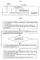
- the functional model of an enhanced bridge device is shown in Fig.2B .
- Fig. 3 shows a block diagram of the device utilizing RPR scheme in the third prior art.
- the device comprises one or more UNIs (standard Ethernet UNIs), two NNIs (synchronous digital transmission channels), and a RPR device 600 (described in IEEE802.17), two mapping and de-mapping devices, and a data processing device 500 which may be a data converging/diverging device or a bridge device).
- the data frames entering the device via the NNI are processed as follows:
- An object of the present invention is to provide a virtual interface device over a SDH/SONET network and the method for data frames access and transport over a SDH/SONET network thereof, in order to improve the access ability.
- one UNI or NNI can be expanded to a plurality of virtual interfaces, each of which corresponds to different users and different services to overcome the disadvantages of the prior art.
- An embodiment of the present invention provides a system according to claim 1.
- Another embodiment of the present invention provides a method according to claim 6.
- the operator may employ the system shown in Fig. 4 to provide Ethernet services for users, which correspond to combinations of a plurality of procedures.
- the operator may define and choose required procedure combinations flexibly according to network topology, the users' service demands and bandwidth resource.
- the commonly used procedure combinations are as follows:
- the device manufacturers may partially or completely employ the system and method according to the present invention. For some devices with simple functions, part of components can be omitted and the procedure is relatively simple. The device manufacturers may even fix the processing through fixing connections among the devices to omit the data processing and dispatching device. For instance, for a device that provides only Ethernet private service, it may comprises only the following devices:
- Said device supports the following combinations of procedures:
- integral VLAN services can be provided for users.
- the system and method of the present invention overcome the restriction on Ethernet data frame address space at UNIs. When a plurality of Ethernet data frames is sent to such a device of the network, there is no restriction on address space of Ethernet data frames.
- a device interface (UNI or NNI) can support both VLAN service and Ethernet data private service, and a plurality of Ethernet data frames from many users can be accessed and converged at a device interface, thus the accessing and converging capability of the device is enhanced greatly.
- the operator may maximize processing capacity of devices and utilization ratio of bandwidth resource through flexible adjustment to internal procedures according to network topology, the users' service demands, and bandwidth resource. 94] With the system and method of the present invention, individualized services can be quickly provided for users. The operator may provide new services for users through creating new flow combinations, without upgrading or purchasing devices.
- data frames entering the virtual interface device via device interfaces are processed after being classified; different data classes will be processed differently which are implemented by the virtual interface device.
- data frames from a device interface may contain various classes, and procedures for different classes of data frames are different; the corresponding relation between procedures and device interfaces is m:n.
- the present invention supports free combination of procedures; the data processing and dispatching device and the combination of its procedures is an important part of the present invention.
- a system lacking of flexibility is unable to adapt to the changing environment.
- the operator can update the procedures of the device dynamically, and users can choose flow combinations provided by the device or create new flow combinations by himself/herself as required. There are 22 procedure combinations available.
- the amount of bridge devices is certain; so conflicts among data frame address spaces of different users can be avoided only through restricting the data frame address spaces of users.
- the virtual bridge devices in the present invention can add virtual bridges dynamically, and the address space of each virtual bridge is independent; different virtual bridges correspond to different users; therefore, the present invention has no restriction to data frame address spaces of users.
- data frames for different users can be isolated, transported and shared by adding a label before sending, changing the label during transport and removing the label at destination address, thus the virtual private device of the present invention is achieved.
- any device has the following 3 functions:
- standard Ethernet interface used in the present invention means the following:
- IEEE802.3 defines the LAN interface in detail; in the present invention, an interface under IEEE802.3 is regarded as a standard Ethernet interface.
- Fig.4 shows a system for different data frames access and transport over a SDH/SONET network.
- the system comprises a plurality of UNIs designed to couple with the user's network; a plurality of NNIs designed to couple with said digital transport network to transport data frames; a plurality of mapping and de-mapping devices 10; a virtual interface device 80 coupled to said UNIs and coupled to said NNIs via said mapping and de-mapping devices 10; a data processing and dispatching device 90 coupled to said virtual interface device 80; a virtual private device 120 and a plurality of virtual bridge devices 100 and an PRP device 110 coupled to said data processing and dispatching device.
- mapping and de-mapping devices 10, said virtual interface device 80, and said data processing and dispatching device 90 constitute the data converting device of the present invention.
- a plurality of virtual private device 120, a virtual bridge device 100 and a PRP device 110 are described in the present invention, it should be noted that a combination of any one or two of them can implement the present invention.
- the input to said system for different data frames access and transport over a digital transport network comprises: (1) data frames entering the virtual interface device via the UNIs; (2) data frames entering the mapping and de-mapping devices via the NNIs.
- the data frames output from said system for different data frames access and transport over a digital transport network comprises: (1) data frames output to external of the virtual interface device via the UNIs; (2) data frames output to external of the mapping and de-mapping device via the NNIs.
- Fig.4 (F) shows the processing steps for data frames entering the virtual interface device via the UNIs according to the system for different data frames access and transport over an SDH/SONET network.
- the device manufacturers may partially or completely employ above method.
- the processing is relatively simple.
- the device manufacturers may even treat the processing as firmware through fixing connections among the devices so as to omit the data processing and dispatching and device.
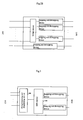
- Fig.4A shows the schematic block diagram of the virtual interface device according to a preferred embodiment of the system for Ethernet data frames access and transport over a SDH/SONET network of the present invention.
- a virtual interface device 80 is used to enhance access ability.
- a device interface (UNI 20 or NNI 30) may be expanded to a plurality of virtual interfaces, each of which corresponds to different users and different services respectively.
- a virtual interface processing unit 800 of the virtual interface device will classify them according to different services required by different users and choose a corresponding processing according to the classification.
- a different processing corresponds to different rules stored in the rule database 850.
- a control interface unit controls the virtual interface processing unit 800 to perform classification according to the instructions from a control interface, and the virtual interface processing unit searches for a corresponding rule stored in the rule database 850 to process the data frames.
- Data frames output from the virtual interface device are transported to a corresponding device interface to output after processing according to the classification in the virtual interface device.
- the virtual interface device stores N rules, the corresponding relation between the device interface and the rules is 1:N.
- the rules in the virtual interface device may be created or deleted dynamically. Therefore, it is easy to modify the rules to enhance the adaptability of the system according to the users' requirements and the updating of the system.
- the virtual interface device also comprises a software loader (not shown) to load different software.
- the virtual interface processing unit 800 is responsible for processing data frames and serves as a processing center; the processing steps and processing logics in the virtual interface processing unit are firmware and can' t be changed during operation of the virtual interface device.
- the rule database is a control center and is responsible for providing relevant processing and control parameters when the virtual interface processing unit processes the data frames. Different parameters lead to different processing actions.
- the rules in the rule database may be updated.
- the control interface unit is provided with an external control interface of the virtual interface device. Via the control interface, the control system of the virtual interface device may monitor the working status of the virtual interface processing unit and performs adding, deleting, modifying, and searching operations on rules in the rule database.
- the rule database may store a plurality of rules, each of which contains five parts: device interface number, data frame class number, data frame address offset, data frame eigenvalue, and data frame comparison mask.
- the virtual interface device is connected with the UNIs or NNIs via device interfaces.
- the corresponding relation between the UNIs (or NNIs) and the device interfaces is 1:1.
- the virtual interface device is connected with the data processing and dispatching device via the inter-device interface.
- the virtual interface device is connected with the control system of the virtual interface device via the control interface.
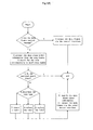
- Fig.4A shows the steps of the virtual interface processing unit processing data frames entering the virtual interface device via a device interface:
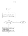
- Fig.4A shows the steps of the virtual interface processing unit processing data frames entering the virtual interface device via the inter-device interface.
- the processing steps performed by the virtual interface processing unit are as follows:
- Fig.5 is the schematic block diagram of the virtual private device according to a preferred embodiment of the system for Ethernet data frames access and transport over an SDH/SONET network of the present invention.
- a virtual private processing unit 8001 is coupled to an inter-device interface to process the data frames through the inter-device interface.
- the virtual private processing unit 8001 is also coupled to a rule database and a control interface unit.
- the control interface unit exchanges data with external via the control interface.
- the present invention enhances converging ability of the system by using the virtual private device.
- the virtual private device stores a plurality of converging rules, a plurality of diverging rules, and a plurality of relay rules (the relay rules are optional and unnecessary in some simple virtual private device).
- the corresponding relation between data classes and the rules is 1:1.
- the rules in the virtual private device can be created and deleted dynamically. Data frames of different users can be isolated, transported and shared over the same physical channel through virtual private device adding a label before sending, changing the label during transport and removing the label at the destination address.
- a virtual private device comprises a virtual private processing unit and a rule database.
- the virtual private processing unit has two major functions:
- the virtual private processing unit is a processing center of the virtual private device; the following items are fixed in the virtual private processing unit:
- the rule database is responsible for the processing action of the virtual private processing unit and serves as a control center.
- the rules in the rule database may be updated dynamically.
- the rule database may store a plurality of rules, each of which comprises the following four parts: input data frame class number, rule type (convergence/divergence/relay), label number, and output data frame class number.
- said virtual private device is connected with the said data processing and dispatching device via the inter-device interface; said virtual private device is connected with the control system of the system of the present invention via the control interface.
- the virtual private device In view of expandability and compatibility, it is recommended to implement the virtual private device with MPLS, GFP, VMAN, or Nested VLAN technology in the present invention.
- the virtual private device manufacturers may also employ self-defined label formats (or self-defined data frame encapsulations) to implement said virtual private device.
- the virtual private device may support a plurality of different technologies at a time.
- Fig.5 (F) shows the flowchart of the virtual private processing; for data frames entering the virtual private device via the inter-device interface, the processing steps of the virtual private processing unit are as follows:
- Fig. 7 is the schematic block diagram of the data processing and dispatching device according to the system for Ethernet data frames access and transport over an SDH/SONET network of the present invention.
- the data processing and dispatching device is coupled to other devices via a plurality of inter-device interfaces to process the data passing through the inter-device interfaces.
- a data processing and dispatching unit coupled to a procedure database and a control interface unit.
- the control interface unit exchanges data with external via a control interface.
- the present invention employs the data processing and dispatching device to implement individualized services to improve serviceability of the device.
- the data processing and dispatching device stores a plurality of procedures in it. The corresponding relation between the procedures and the data frame classes is 1:1.
- the data processing and dispatching device finds a corresponding procedure according to a data frame class, and informs other corresponding devices to process the data frames according to the procedure.
- the procedure in the data frame processing and dispatching device may be created, modified, or deleted dynamically.
- the operator may quickly provide individualized services to maximize the efficacy of the data processing and dispatching device through dynamically adding, modifying, and deleting the procedures in the data processing and dispatching device.
- the data processing and dispatching unit is the processing center of the data processing and dispatching device, in which the processing steps are fixed.
- the data processing and dispatching device comprises the plurality of inter-device interfaces, each of which corresponds to a unique external device. The corresponding relation between the inter-device interfaces and the external devices are fixed.
- the procedure database is the control center of the data processing and dispatching device, and may be updated dynamically.
- Each procedure in the procedure database contains the following information:
- the data processing and dispatching device is connected with other devices via the inter-device interfaces, each of the inter-device interfaces corresponds to a virtual bridge device, a virtual private device, an RPR device, or a virtual interface device.
- the data processing and dispatching device is connected with the control system of the system of the present invention via the control interface.
- Fig.6 is the schematic block diagram of the virtual bridge device according to a preferred embodiment of the system for Ethernet data frames access and transport over a SDH/SONET network of the present invention.
- the present invention overcomes the problem of limited Ethernet data frame address space with virtual bridge devices.
- a virtual bridge device may provide a plurality of virtual bridges. Each virtual bridge possesses all functions and properties of a bridge device. However, it differs from the bridge device in that the virtual bridge may be created and deleted dynamically.
- the operator may create or delete a plurality of virtual bridges dynamically because each virtual bridge has an independent address space, the operator may provide VLAN services to users with different virtual bridges if that conflicts exists among address spaces.
- a virtual bridge device comprises a virtual bridge processing unit 802, a multicasting database 856, a control interface unit, a forwarding database 852, and a virtual bridge database 854.
- the virtual bridge processing unit has 3 major functions:
- the virtual bridge processing unit is the processing center of the virtual bridge device, and there are five items embedded in it:
- the virtual bridge database, the multicasting database, and the forwarding database are responsible for the processing action of the virtual bridge processing unit, and the items in the databases may be updated during operation of the virtual bridge device.
- the data formats of items in the multicasting database and the forwarding database are identical, and each item contains the following fields:
- the database code is the combination of all fields; in the forwarding database, the database code is the combination of all fields except for the output port of virtual bridge.
- an external control system of the virtual bridge device may implement the following functions:
- the virtual bridge device is connected with the data processing and dispatching device via the inter-device interface.
- the virtual bridge device is connected with the control system of the system of the present invention via the control interface.
- Fig.6 (F1) is the flowchart of the virtual bridge device processing the incoming data frames from the inter-device interface according to a preferred embodiment of the system for Ethernet data frames access and transport over an SDH/SONET network of the present invention.
- the virtual bridge processing unit For data frames entering the virtual bridge device via the inter-device interface, the virtual bridge processing unit performs the following processing steps:
- Fig.7 (F) is the flowchart of the data processing and dispatching device processing the incoming data frames according to a preferred embodiment of the system for Ethernet data frames access and transport over a synchronous digital transport network of the present invention.
- the data processing and dispatching unit processes the incoming data frames as follows:
Landscapes
- Engineering & Computer Science (AREA)
- Computer Networks & Wireless Communication (AREA)
- Signal Processing (AREA)
- Computer Security & Cryptography (AREA)
- Data Exchanges In Wide-Area Networks (AREA)
- Time-Division Multiplex Systems (AREA)
- Circuits Of Receivers In General (AREA)
- Communication Control (AREA)
- Small-Scale Networks (AREA)
Claims (15)
- System für den Zugriff und die Übertragung von Datenrahmen mit unterschiedlichen Rahmenformaten, umfassend:mindestens eine Benutzer-Netzwerk-Schnittstelle, im Folgenden als UNI bezeichnet, die mit einem Benutzer-Netzwerk gekoppelt ist; und/odermindestens eine Netzwerk-Netzwerk-Schnittstelle, im Folgenden als NNI bezeichnet, die mit einem digitalen Übertragungsnetz gekoppelt ist; undeine Daten-Umwandlungs-Vorrichtung, die mit der mindestens einen UNI und/oder der mindestens einen NNI gekoppelt ist, um die Rahmenformate der zwischen den UNIs übertragenen Datenrahmen, und/oder die Rahmenformate der zwischen den NNIs übertragenen Datenrahmen, und/oder die Rahmenformate der zwischen der NNI und der UNI übertragenen Datenrahmen umzuwandeln;wobei die Daten-Umwandlungs-Vorrichtung dadurch gekennzeichnet ist, dass sie eine virtuelle Schnittstellen-Vorrichtung (80) enthält,
wobei die virtuelle Schnittstellen-Vorrichtung folgendes umfasst: Mindestens zwei Vorrichtungs-Schnittstellen zur Eingabe oder Ausgabe von Datenrahmen; eine virtuelle Schnittstellen-Verarbeitungs-Einheit (800), die mit der Vorrichtungs-Schnittstelle gekoppelt ist, um die Datenrahmen zu verarbeiten und Datenrahmen zwischen der virtuellen Schnittstellen-Verarbeitungs-Einheit (800) und der Vorrichtungs-Schnittstelle auszutauschen; eine Regel-Datenbank (850), die mit der virtuelle Schnittstellen-Verarbeitungs-Einheit (800) gekoppelt ist und Regeln speichert, die verschiedenen Datenrahmen-Formaten entsprechen, um die virtuelle Schnittstellen-Verarbeitungs-Einheit (800) in die Lage zu versetzen, die Datenrahmen zu klassifizieren und Prozeduren für verschiedene Klassen der Datenrahmen gemäß Regeln zu bestimmen; eine Steuerungs-Schnittstellen-Einheit (900), die mit der Regel-Datenbank (850) und der virtuellen Schnittstellen-Verarbeitungs-Einheit (800) gekoppelt ist und sie steuert; und eine Schnittstelle zwischen den Vorrichtungen, die mit der virtuellen Schnittstellen-Verarbeitungs-Einheit (800) gekoppelt ist, um mit externen Vorrichtungen gekoppelt zu werden, um Datenrahmen auszutauschen. - System gemäß Anspruch 1, wobei die entsprechende Relation zwischen den Vorrichtungs-Schnittstellen und den Regeln 1:N ist, wobei N eine natürliche Zahl größer oder gleich 1 ist, und jede Vorrichtungs-Schnittstelle als Vorrichtungs-Schnittstelle konfiguriert ist, welche die Anforderung der Datenschnittstelle erfüllt, die einer beliebigen der Regeln entspricht.
- System gemäß Anspruch 1 oder 2, wobei die Steuerungs-Schnittstellen-Einheit (900) eine Steuerungs-Schnittstelle bereitstellt, über die der Betrieb der virtuellen Schnittstellen-Verarbeitungs-Einheit (800) überwacht werden kann, und über die Operationen auf Regeln in den Regel-Datenbanken (850) hinzugefügt, gelöscht, geändert und gesucht werden können.
- System gemäß Anspruch 3, wobei eine Regel eine Vorrichtungs-Schnittstellen-Nummer, eine Datenrahmen-Klassen-Nummer, einen Datenrahmen Adressen-Versatz, einen Datenrahmen-Eigenwert und eine Datenrahmen-Vergleichs-Maske enthält, die Verarbeitungs- und Steuerungs-Parameter bereitstellen, wenn die virtuelle Schnittstellen-Verarbeitungs-Einheit (800) die Datenrahmen verarbeitet.
- System gemäß Anspruch 1, wobei
die Vorrichtungs-Schnittstelle mit der mindestens einen UNI oder der mindestens einen NNI verbunden ist,
die virtuelle Schnittstellen-Vorrichtung (80) über die Schnittstelle zwischen den Vorrichtungen (860) mit der Datenverarbeitungs- und Abfertigungs-Vorrichtung (90) verbunden ist, und
die entsprechende Relation zwischen den Vorrichtungs-Schnittstellen und der mindestens einen UNI oder der mindestens einen NNI 1:1 ist. - Verfahren für den Zugriff und die Übertragung von Datenrahmen über ein digitales Übertragungsnetz unter Verwendung des Systems aus Anspruch 1, wobei das System eine Daten-Umwandlungs-Vorrichtung enthält, die dadurch gekennzeichnet ist, dass sie eine virtuelle Schnittstellen-Vorrichtung (80) enthält, wobei das Verfahren folgende Schritte umfasst:Suchen nach einer ersten Regel, die einer Vorrichtungs-Schnittstelle entspricht;Feststellen, ob die erste Regel gefunden wurde, wenn die erste Regel nicht gefunden wurde, Beenden des Prozesses;Wenn die erste Regel gefunden wurde, Erhalten einer Datenrahmen-Klassen-Nummer;Feststellen, ob die Datenrahmen-Klassen-Nummer einer zweiten Regel entspricht;Wenn die Datenrahmen-Klassen-Nummer nicht einer zweiten Regel entspricht, Suchen nach einer nächsten Regel, die der Vorrichtungs-Schnittstelle entspricht, und Rückkehr zur Feststellung, ob die erste Regel gefunden wurde;Wenn die Datenrahmen-Klassen-Nummer einer zweiten Regel entspricht, Ändern der Datenrahmen, Senden der Datenrahmen über eine Schnittstelle zwischen den Vorrichtungen, und dann Beenden des Prozesses.
- Verfahren gemäß Anspruch 6, wobei die virtuelle Schnittstellen-Vorrichtung (80) die Datenrahmen, die über die Schnittstelle zwischen den Vorrichtungen eintreffen, entsprechen der folgenden Schritte verarbeitet:Entnahme einer Datenrahmen-Klassen-Nummer, entsprechend dieser Suchen nach einer Regel, die der Datenrahmen-Typ-Nummer in der Regel-Datenbank (850) entspricht;wenn die Regel nicht gefunden wird, Verwerfen der Datenrahmen und Beenden des Prozesses;wenn die Regel gefunden wird, Ändern der Datenrahmen und Senden der Datenrahmen entsprechend der Regel an eine der Vorrichtungs-Schnittstellen.
- Verfahren gemäß Anspruch 6, wobei der Schritt des Suchens einer ersten Regel, die einer Vorrichtungs-Schnittstelle entspricht, folgendes umfasst: Durchführen einer Suche in einer Regel-Datenbank (850) mit dem Index einer Vorrichtungs-Schnittstellen-Nummer der Vorrichtungs-Schnittstelle, welche die Datenrahmen empfängt.
- Verfahren gemäß Anspruch 6, wobei der Schritt des Beendens des Prozesses, wenn die erste Regel nicht gefunden wird, ferner einen Schritt der Ausgabe eines Berichtes und des Verwerfens der Datenrahmen umfasst.
- Verfahren gemäß Anspruch 6, wobei der Schritt des Erhaltens einer Datenrahmen-Klassen-Nummer folgendes umfasst:Lesen von Information am Adressen-Versatz der Datenrahmen gemäß dem Datenrahmen-Adressen-Versatz in der ersten Regel, und Durchführen einer bitweisen UND-Operation zwischen der gelesenen Information und der Datenrahmen-Vergleichs-Maske in der ersten Regel.
- Verfahren gemäß Anspruch 10, wobei der Schritt des Bestimmens, ob die Datenrahmen-Klassen-Nummer der zweiten Regel entspricht, einen Schritt des Vergleichens der Datenrahmen-Klassen-Nummer mit einem Datenrahmen-Eigenwert in der ersten Regel umfasst.
- Verfahren gemäß Anspruch 10, wobei der Schritt des Änderns der Datenrahmen einen Schritt des Einfügens der Daten-Klassen-Nummer in einen Kopf der Datenrahmen umfasst.
- Verfahren gemäß Anspruch 7, wobei der Schritt des Entnehmens der Datenrahmen-Klassen-Nummer einen Schritt des Entnehmens der Datenrahmen-Klassen-Nummer aus einem Kopf der Datenrahmen umfasst.
- Verfahren gemäß Anspruch 13, wobei der Schritt des Suchens nach einer Regel, die der Datenrahmen-Typ-Nummer entspricht, in der Regel-Datenbank (850) einen Schritt des Suchens in der Regel-Datenbank (850) mit einem Index der Datenrahmen-Klassen-Nummer umfasst.
- Verfahren gemäß Anspruch 14, wobei die Schritte des Änderns der Datenrahmen und des Sendens der Datenrahmen an eine der Vorrichtungs-Schnittstellen entsprechend der Regel folgendes umfassen: Löschen der Daten-Klassen-Nummer im Kopf der Datenrahmen und Senden der Datenrahmen an eine der Vorrichtungs-Schnittstellen entsprechend der Vorrichtungs-Schnittstellen-Nummer in der Regel.
Applications Claiming Priority (3)
| Application Number | Priority Date | Filing Date | Title |
|---|---|---|---|
| CN03103094 | 2003-01-28 | ||
| CNB031030947A CN1303789C (zh) | 2003-01-28 | 2003-01-28 | 数字传送网上不同的数据帧接入和传送的系统和方法 |
| PCT/CN2003/000675 WO2004068789A1 (en) | 2003-01-28 | 2003-08-13 | Method and system for receiving and transmitting different data frames on digital tranmission network |
Publications (3)
| Publication Number | Publication Date |
|---|---|
| EP1594256A1 EP1594256A1 (de) | 2005-11-09 |
| EP1594256A4 EP1594256A4 (de) | 2006-06-28 |
| EP1594256B1 true EP1594256B1 (de) | 2008-03-19 |
Family
ID=32778663
Family Applications (1)
| Application Number | Title | Priority Date | Filing Date |
|---|---|---|---|
| EP03815515A Expired - Lifetime EP1594256B1 (de) | 2003-01-28 | 2003-08-13 | Verfahren und System zum empfangen und senden verschiedener Datenrahmen in einem digitalen Übertragungsnetz |
Country Status (7)
| Country | Link |
|---|---|
| US (1) | US7505481B2 (de) |
| EP (1) | EP1594256B1 (de) |
| CN (1) | CN1303789C (de) |
| AT (1) | ATE389993T1 (de) |
| AU (1) | AU2003255117A1 (de) |
| DE (1) | DE60319882T2 (de) |
| WO (1) | WO2004068789A1 (de) |
Families Citing this family (9)
| Publication number | Priority date | Publication date | Assignee | Title |
|---|---|---|---|---|
| US7653526B1 (en) * | 2002-08-16 | 2010-01-26 | Cisco Technology, Inc. | Method and system for emulating an ethernet link over a sonet path |
| CN100440824C (zh) * | 2003-01-28 | 2008-12-03 | 华为技术有限公司 | 数字传送网上不同的数据帧接入和传送的方法 |
| US20060080467A1 (en) * | 2004-08-26 | 2006-04-13 | Sensory Networks, Inc. | Apparatus and method for high performance data content processing |
| US20070140271A1 (en) * | 2005-12-21 | 2007-06-21 | Amante Shane M | Method and system for terminating SONET/SDH circuits in an IP network |
| US7639699B2 (en) * | 2006-08-04 | 2009-12-29 | Cisco Technology, Inc. | Technique for sharing a physical port among a plurality of virtual bridges on a switch in a computer network |
| CN102316528B (zh) * | 2010-07-06 | 2015-06-03 | 中兴通讯股份有限公司 | 基于网络共享资源管理的方法及系统 |
| US8934783B2 (en) | 2011-02-17 | 2015-01-13 | International Business Machines Corporation | Adaptor system for an ethernet network |
| US11070395B2 (en) * | 2015-12-09 | 2021-07-20 | Nokia Of America Corporation | Customer premises LAN expansion |
| CN113676404A (zh) * | 2021-08-23 | 2021-11-19 | 北京字节跳动网络技术有限公司 | 数据传输方法、装置、设备、存储介质及程序 |
Family Cites Families (7)
| Publication number | Priority date | Publication date | Assignee | Title |
|---|---|---|---|---|
| GB9311935D0 (en) * | 1993-06-09 | 1993-07-28 | Madge Networks Ltd | Processor |
| US6122281A (en) * | 1996-07-22 | 2000-09-19 | Cabletron Systems, Inc. | Method and apparatus for transmitting LAN data over a synchronous wide area network |
| US6233611B1 (en) * | 1998-05-08 | 2001-05-15 | Sony Corporation | Media manager for controlling autonomous media devices within a network environment and managing the flow and format of data between the devices |
| CN1257691A (zh) * | 1999-12-21 | 2000-06-28 | 易际平 | 一种具有远程数据传送功能的脑电检查仪 |
| US20040076166A1 (en) * | 2002-10-21 | 2004-04-22 | Patenaude Jean-Marc Guy | Multi-service packet network interface |
| CN100484054C (zh) * | 2003-01-28 | 2009-04-29 | 华为技术有限公司 | 数字传送网上不同的数据帧接入和传送的系统和方法 |
| CN100396035C (zh) * | 2003-01-28 | 2008-06-18 | 华为技术有限公司 | 数字传送网上不同的数据帧接入和传送的系统和方法 |
-
2003
- 2003-01-28 CN CNB031030947A patent/CN1303789C/zh not_active Expired - Lifetime
- 2003-08-13 WO PCT/CN2003/000675 patent/WO2004068789A1/zh not_active Ceased
- 2003-08-13 AU AU2003255117A patent/AU2003255117A1/en not_active Abandoned
- 2003-08-13 AT AT03815515T patent/ATE389993T1/de not_active IP Right Cessation
- 2003-08-13 DE DE60319882T patent/DE60319882T2/de not_active Expired - Lifetime
- 2003-08-13 EP EP03815515A patent/EP1594256B1/de not_active Expired - Lifetime
-
2004
- 2004-01-28 US US10/765,204 patent/US7505481B2/en active Active
Also Published As
| Publication number | Publication date |
|---|---|
| EP1594256A4 (de) | 2006-06-28 |
| CN1303789C (zh) | 2007-03-07 |
| US20050008029A1 (en) | 2005-01-13 |
| US7505481B2 (en) | 2009-03-17 |
| EP1594256A1 (de) | 2005-11-09 |
| CN1522004A (zh) | 2004-08-18 |
| WO2004068789A1 (en) | 2004-08-12 |
| DE60319882D1 (de) | 2008-04-30 |
| AU2003255117A1 (en) | 2004-08-23 |
| DE60319882T2 (de) | 2009-02-05 |
| ATE389993T1 (de) | 2008-04-15 |
Similar Documents
| Publication | Publication Date | Title |
|---|---|---|
| US7565453B2 (en) | System and method for accessing and transmitting different data frames in a digital transmission network | |
| US5732080A (en) | Method and apparatus for controlling data flow within a switching device | |
| JP4115721B2 (ja) | スイッチングノードのための分類およびタグ付け規則 | |
| JP2004140776A (ja) | ネットワークにおけるフレーム転送方法及びノード、フレーム転送プログラム | |
| JPH11261641A (ja) | ルータ装置及びフレーム転送方法 | |
| US7565455B2 (en) | System and method of accessing and transmitting different data frames in a digital transmission network | |
| US6791948B1 (en) | Distributed switch and connection control arrangement and method for digital communications network | |
| JP5526047B2 (ja) | パケット中継装置およびパケット中継装置における出力先決定方法 | |
| EP1589697B1 (de) | Verfahren und System zum Empfangen und Senden verschiedener Datenrahmen auf einem digitalen Übertragungsnetzwerk | |
| EP1594256B1 (de) | Verfahren und System zum empfangen und senden verschiedener Datenrahmen in einem digitalen Übertragungsnetz | |
| US7394810B2 (en) | Layer 2 switch and method of processing expansion VLAN tag of layer 2 frame | |
| US7797444B2 (en) | Data transfer apparatus and data transfer system | |
| US8064465B2 (en) | Packet forwarding apparatus | |
| US8064456B2 (en) | Frame relay apparatus and route learning method | |
| EP1594257A1 (de) | Verfahren und system zum empfangen und senden verschiedener datenrahmen in einem digitalen übertragungsnetz | |
| JP2004266874A (ja) | ネットワークにおけるフレーム転送方法及びノード、フレーム転送プログラム | |
| JP4587962B2 (ja) | Mac装置とそれを用いたブリッジ装置およびプログラム |
Legal Events
| Date | Code | Title | Description |
|---|---|---|---|
| PUAI | Public reference made under article 153(3) epc to a published international application that has entered the european phase |
Free format text: ORIGINAL CODE: 0009012 |
|
| 17P | Request for examination filed |
Effective date: 20050826 |
|
| AK | Designated contracting states |
Kind code of ref document: A1 Designated state(s): AT BE BG CH CY CZ DE DK EE ES FI FR GB GR HU IE IT LI LU MC NL PT RO SE SI SK TR |
|
| AX | Request for extension of the european patent |
Extension state: AL LT LV MK |
|
| DAX | Request for extension of the european patent (deleted) | ||
| A4 | Supplementary search report drawn up and despatched |
Effective date: 20060526 |
|
| 17Q | First examination report despatched |
Effective date: 20060926 |
|
| R17C | First examination report despatched (corrected) |
Effective date: 20060926 |
|
| GRAP | Despatch of communication of intention to grant a patent |
Free format text: ORIGINAL CODE: EPIDOSNIGR1 |
|
| RTI1 | Title (correction) |
Free format text: METHOD AND SYSTEM FOR RECEIVING AND TRANSMITTING DIFFERENT DATA FRAMES ON DIGITAL TRANSMISSION NETWORK |
|
| GRAS | Grant fee paid |
Free format text: ORIGINAL CODE: EPIDOSNIGR3 |
|
| GRAA | (expected) grant |
Free format text: ORIGINAL CODE: 0009210 |
|
| AK | Designated contracting states |
Kind code of ref document: B1 Designated state(s): AT BE BG CH CY CZ DE DK EE ES FI FR GB GR HU IE IT LI LU MC NL PT RO SE SI SK TR |
|
| REG | Reference to a national code |
Ref country code: GB Ref legal event code: FG4D |
|
| REG | Reference to a national code |
Ref country code: CH Ref legal event code: EP |
|
| REF | Corresponds to: |
Ref document number: 60319882 Country of ref document: DE Date of ref document: 20080430 Kind code of ref document: P |
|
| REG | Reference to a national code |
Ref country code: IE Ref legal event code: FG4D |
|
| PG25 | Lapsed in a contracting state [announced via postgrant information from national office to epo] |
Ref country code: FI Free format text: LAPSE BECAUSE OF FAILURE TO SUBMIT A TRANSLATION OF THE DESCRIPTION OR TO PAY THE FEE WITHIN THE PRESCRIBED TIME-LIMIT Effective date: 20080319 |
|
| PG25 | Lapsed in a contracting state [announced via postgrant information from national office to epo] |
Ref country code: AT Free format text: LAPSE BECAUSE OF FAILURE TO SUBMIT A TRANSLATION OF THE DESCRIPTION OR TO PAY THE FEE WITHIN THE PRESCRIBED TIME-LIMIT Effective date: 20080319 |
|
| NLV1 | Nl: lapsed or annulled due to failure to fulfill the requirements of art. 29p and 29m of the patents act | ||
| PG25 | Lapsed in a contracting state [announced via postgrant information from national office to epo] |
Ref country code: SI Free format text: LAPSE BECAUSE OF FAILURE TO SUBMIT A TRANSLATION OF THE DESCRIPTION OR TO PAY THE FEE WITHIN THE PRESCRIBED TIME-LIMIT Effective date: 20080319 Ref country code: BE Free format text: LAPSE BECAUSE OF FAILURE TO SUBMIT A TRANSLATION OF THE DESCRIPTION OR TO PAY THE FEE WITHIN THE PRESCRIBED TIME-LIMIT Effective date: 20080319 |
|
| PG25 | Lapsed in a contracting state [announced via postgrant information from national office to epo] |
Ref country code: SE Free format text: LAPSE BECAUSE OF FAILURE TO SUBMIT A TRANSLATION OF THE DESCRIPTION OR TO PAY THE FEE WITHIN THE PRESCRIBED TIME-LIMIT Effective date: 20080619 Ref country code: SK Free format text: LAPSE BECAUSE OF FAILURE TO SUBMIT A TRANSLATION OF THE DESCRIPTION OR TO PAY THE FEE WITHIN THE PRESCRIBED TIME-LIMIT Effective date: 20080319 Ref country code: ES Free format text: LAPSE BECAUSE OF FAILURE TO SUBMIT A TRANSLATION OF THE DESCRIPTION OR TO PAY THE FEE WITHIN THE PRESCRIBED TIME-LIMIT Effective date: 20080630 Ref country code: PT Free format text: LAPSE BECAUSE OF FAILURE TO SUBMIT A TRANSLATION OF THE DESCRIPTION OR TO PAY THE FEE WITHIN THE PRESCRIBED TIME-LIMIT Effective date: 20080826 Ref country code: CZ Free format text: LAPSE BECAUSE OF FAILURE TO SUBMIT A TRANSLATION OF THE DESCRIPTION OR TO PAY THE FEE WITHIN THE PRESCRIBED TIME-LIMIT Effective date: 20080319 |
|
| ET | Fr: translation filed | ||
| PG25 | Lapsed in a contracting state [announced via postgrant information from national office to epo] |
Ref country code: RO Free format text: LAPSE BECAUSE OF FAILURE TO SUBMIT A TRANSLATION OF THE DESCRIPTION OR TO PAY THE FEE WITHIN THE PRESCRIBED TIME-LIMIT Effective date: 20080319 Ref country code: NL Free format text: LAPSE BECAUSE OF FAILURE TO SUBMIT A TRANSLATION OF THE DESCRIPTION OR TO PAY THE FEE WITHIN THE PRESCRIBED TIME-LIMIT Effective date: 20080319 |
|
| PLBE | No opposition filed within time limit |
Free format text: ORIGINAL CODE: 0009261 |
|
| STAA | Information on the status of an ep patent application or granted ep patent |
Free format text: STATUS: NO OPPOSITION FILED WITHIN TIME LIMIT |
|
| PG25 | Lapsed in a contracting state [announced via postgrant information from national office to epo] |
Ref country code: DK Free format text: LAPSE BECAUSE OF FAILURE TO SUBMIT A TRANSLATION OF THE DESCRIPTION OR TO PAY THE FEE WITHIN THE PRESCRIBED TIME-LIMIT Effective date: 20080319 |
|
| 26N | No opposition filed |
Effective date: 20081222 |
|
| PG25 | Lapsed in a contracting state [announced via postgrant information from national office to epo] |
Ref country code: MC Free format text: LAPSE BECAUSE OF NON-PAYMENT OF DUE FEES Effective date: 20080831 |
|
| REG | Reference to a national code |
Ref country code: CH Ref legal event code: PL |
|
| GBPC | Gb: european patent ceased through non-payment of renewal fee |
Effective date: 20080813 |
|
| PG25 | Lapsed in a contracting state [announced via postgrant information from national office to epo] |
Ref country code: EE Free format text: LAPSE BECAUSE OF FAILURE TO SUBMIT A TRANSLATION OF THE DESCRIPTION OR TO PAY THE FEE WITHIN THE PRESCRIBED TIME-LIMIT Effective date: 20080319 Ref country code: BG Free format text: LAPSE BECAUSE OF FAILURE TO SUBMIT A TRANSLATION OF THE DESCRIPTION OR TO PAY THE FEE WITHIN THE PRESCRIBED TIME-LIMIT Effective date: 20080619 |
|
| PG25 | Lapsed in a contracting state [announced via postgrant information from national office to epo] |
Ref country code: LI Free format text: LAPSE BECAUSE OF NON-PAYMENT OF DUE FEES Effective date: 20080831 Ref country code: CH Free format text: LAPSE BECAUSE OF NON-PAYMENT OF DUE FEES Effective date: 20080831 |
|
| PG25 | Lapsed in a contracting state [announced via postgrant information from national office to epo] |
Ref country code: IE Free format text: LAPSE BECAUSE OF NON-PAYMENT OF DUE FEES Effective date: 20080813 |
|
| PG25 | Lapsed in a contracting state [announced via postgrant information from national office to epo] |
Ref country code: IT Free format text: LAPSE BECAUSE OF FAILURE TO SUBMIT A TRANSLATION OF THE DESCRIPTION OR TO PAY THE FEE WITHIN THE PRESCRIBED TIME-LIMIT Effective date: 20080319 |
|
| PG25 | Lapsed in a contracting state [announced via postgrant information from national office to epo] |
Ref country code: CY Free format text: LAPSE BECAUSE OF FAILURE TO SUBMIT A TRANSLATION OF THE DESCRIPTION OR TO PAY THE FEE WITHIN THE PRESCRIBED TIME-LIMIT Effective date: 20080319 |
|
| PG25 | Lapsed in a contracting state [announced via postgrant information from national office to epo] |
Ref country code: GB Free format text: LAPSE BECAUSE OF NON-PAYMENT OF DUE FEES Effective date: 20080813 |
|
| PG25 | Lapsed in a contracting state [announced via postgrant information from national office to epo] |
Ref country code: LU Free format text: LAPSE BECAUSE OF NON-PAYMENT OF DUE FEES Effective date: 20080813 Ref country code: HU Free format text: LAPSE BECAUSE OF FAILURE TO SUBMIT A TRANSLATION OF THE DESCRIPTION OR TO PAY THE FEE WITHIN THE PRESCRIBED TIME-LIMIT Effective date: 20080920 |
|
| PG25 | Lapsed in a contracting state [announced via postgrant information from national office to epo] |
Ref country code: TR Free format text: LAPSE BECAUSE OF FAILURE TO SUBMIT A TRANSLATION OF THE DESCRIPTION OR TO PAY THE FEE WITHIN THE PRESCRIBED TIME-LIMIT Effective date: 20080319 |
|
| PG25 | Lapsed in a contracting state [announced via postgrant information from national office to epo] |
Ref country code: GR Free format text: LAPSE BECAUSE OF FAILURE TO SUBMIT A TRANSLATION OF THE DESCRIPTION OR TO PAY THE FEE WITHIN THE PRESCRIBED TIME-LIMIT Effective date: 20080620 |
|
| REG | Reference to a national code |
Ref country code: FR Ref legal event code: PLFP Year of fee payment: 14 |
|
| REG | Reference to a national code |
Ref country code: FR Ref legal event code: PLFP Year of fee payment: 15 |
|
| REG | Reference to a national code |
Ref country code: FR Ref legal event code: PLFP Year of fee payment: 16 |
|
| PGFP | Annual fee paid to national office [announced via postgrant information from national office to epo] |
Ref country code: DE Payment date: 20220608 Year of fee payment: 20 |
|
| PGFP | Annual fee paid to national office [announced via postgrant information from national office to epo] |
Ref country code: FR Payment date: 20220709 Year of fee payment: 20 |
|
| REG | Reference to a national code |
Ref country code: DE Ref legal event code: R071 Ref document number: 60319882 Country of ref document: DE |