EP1593948A1 - Load-measuring device for rolling bearing unit and rolling bearing unit for load measurement - Google Patents

Load-measuring device for rolling bearing unit and rolling bearing unit for load measurement Download PDF

Info

Publication number
EP1593948A1
EP1593948A1 EP04708026A EP04708026A EP1593948A1 EP 1593948 A1 EP1593948 A1 EP 1593948A1 EP 04708026 A EP04708026 A EP 04708026A EP 04708026 A EP04708026 A EP 04708026A EP 1593948 A1 EP1593948 A1 EP 1593948A1
Authority
EP
European Patent Office
Prior art keywords
rolling bearing
sensor
bearing unit
ring
revolution speed
Prior art date
Legal status (The legal status is an assumption and is not a legal conclusion. Google has not performed a legal analysis and makes no representation as to the accuracy of the status listed.)
Ceased
Application number
EP04708026A
Other languages
German (de)
French (fr)
Other versions
EP1593948A4 (en
Inventor
Tomoyuki NSK Ltd. YANAGISAWA
Katsutoshi NSK Ltd. MATSUOKA
Ikunori NSK Ltd. Sakatani
Shin NSK Ltd. KUMAGAI
Current Assignee (The listed assignees may be inaccurate. Google has not performed a legal analysis and makes no representation or warranty as to the accuracy of the list.)
NSK Ltd
Original Assignee
NSK Ltd
Priority date (The priority date is an assumption and is not a legal conclusion. Google has not performed a legal analysis and makes no representation as to the accuracy of the date listed.)
Filing date
Publication date
Application filed by NSK Ltd filed Critical NSK Ltd
Publication of EP1593948A1 publication Critical patent/EP1593948A1/en
Publication of EP1593948A4 publication Critical patent/EP1593948A4/en
Ceased legal-status Critical Current

Links

Images

Classifications

    • GPHYSICS
    • G01MEASURING; TESTING
    • G01LMEASURING FORCE, STRESS, TORQUE, WORK, MECHANICAL POWER, MECHANICAL EFFICIENCY, OR FLUID PRESSURE
    • G01L5/00Apparatus for, or methods of, measuring force, work, mechanical power, or torque, specially adapted for specific purposes
    • FMECHANICAL ENGINEERING; LIGHTING; HEATING; WEAPONS; BLASTING
    • F16ENGINEERING ELEMENTS AND UNITS; GENERAL MEASURES FOR PRODUCING AND MAINTAINING EFFECTIVE FUNCTIONING OF MACHINES OR INSTALLATIONS; THERMAL INSULATION IN GENERAL
    • F16CSHAFTS; FLEXIBLE SHAFTS; ELEMENTS OR CRANKSHAFT MECHANISMS; ROTARY BODIES OTHER THAN GEARING ELEMENTS; BEARINGS
    • F16C19/00Bearings with rolling contact, for exclusively rotary movement
    • F16C19/52Bearings with rolling contact, for exclusively rotary movement with devices affected by abnormal or undesired conditions
    • F16C19/522Bearings with rolling contact, for exclusively rotary movement with devices affected by abnormal or undesired conditions related to load on the bearing, e.g. bearings with load sensors or means to protect the bearing against overload
    • FMECHANICAL ENGINEERING; LIGHTING; HEATING; WEAPONS; BLASTING
    • F16ENGINEERING ELEMENTS AND UNITS; GENERAL MEASURES FOR PRODUCING AND MAINTAINING EFFECTIVE FUNCTIONING OF MACHINES OR INSTALLATIONS; THERMAL INSULATION IN GENERAL
    • F16CSHAFTS; FLEXIBLE SHAFTS; ELEMENTS OR CRANKSHAFT MECHANISMS; ROTARY BODIES OTHER THAN GEARING ELEMENTS; BEARINGS
    • F16C19/00Bearings with rolling contact, for exclusively rotary movement
    • F16C19/02Bearings with rolling contact, for exclusively rotary movement with bearing balls essentially of the same size in one or more circular rows
    • F16C19/14Bearings with rolling contact, for exclusively rotary movement with bearing balls essentially of the same size in one or more circular rows for both radial and axial load
    • F16C19/18Bearings with rolling contact, for exclusively rotary movement with bearing balls essentially of the same size in one or more circular rows for both radial and axial load with two or more rows of balls
    • FMECHANICAL ENGINEERING; LIGHTING; HEATING; WEAPONS; BLASTING
    • F16ENGINEERING ELEMENTS AND UNITS; GENERAL MEASURES FOR PRODUCING AND MAINTAINING EFFECTIVE FUNCTIONING OF MACHINES OR INSTALLATIONS; THERMAL INSULATION IN GENERAL
    • F16CSHAFTS; FLEXIBLE SHAFTS; ELEMENTS OR CRANKSHAFT MECHANISMS; ROTARY BODIES OTHER THAN GEARING ELEMENTS; BEARINGS
    • F16C33/00Parts of bearings; Special methods for making bearings or parts thereof
    • F16C33/30Parts of ball or roller bearings
    • F16C33/58Raceways; Race rings
    • GPHYSICS
    • G01MEASURING; TESTING
    • G01LMEASURING FORCE, STRESS, TORQUE, WORK, MECHANICAL POWER, MECHANICAL EFFICIENCY, OR FLUID PRESSURE
    • G01L5/00Apparatus for, or methods of, measuring force, work, mechanical power, or torque, specially adapted for specific purposes
    • G01L5/0009Force sensors associated with a bearing
    • G01L5/0023Force sensors associated with a bearing by using magnetic sensors
    • GPHYSICS
    • G01MEASURING; TESTING
    • G01MTESTING STATIC OR DYNAMIC BALANCE OF MACHINES OR STRUCTURES; TESTING OF STRUCTURES OR APPARATUS, NOT OTHERWISE PROVIDED FOR
    • G01M13/00Testing of machine parts
    • G01M13/04Bearings
    • GPHYSICS
    • G01MEASURING; TESTING
    • G01PMEASURING LINEAR OR ANGULAR SPEED, ACCELERATION, DECELERATION, OR SHOCK; INDICATING PRESENCE, ABSENCE, OR DIRECTION, OF MOVEMENT
    • G01P3/00Measuring linear or angular speed; Measuring differences of linear or angular speeds
    • G01P3/42Devices characterised by the use of electric or magnetic means
    • G01P3/44Devices characterised by the use of electric or magnetic means for measuring angular speed
    • G01P3/48Devices characterised by the use of electric or magnetic means for measuring angular speed by measuring frequency of generated current or voltage
    • G01P3/481Devices characterised by the use of electric or magnetic means for measuring angular speed by measuring frequency of generated current or voltage of pulse signals
    • G01P3/487Devices characterised by the use of electric or magnetic means for measuring angular speed by measuring frequency of generated current or voltage of pulse signals delivered by rotating magnets
    • FMECHANICAL ENGINEERING; LIGHTING; HEATING; WEAPONS; BLASTING
    • F16ENGINEERING ELEMENTS AND UNITS; GENERAL MEASURES FOR PRODUCING AND MAINTAINING EFFECTIVE FUNCTIONING OF MACHINES OR INSTALLATIONS; THERMAL INSULATION IN GENERAL
    • F16CSHAFTS; FLEXIBLE SHAFTS; ELEMENTS OR CRANKSHAFT MECHANISMS; ROTARY BODIES OTHER THAN GEARING ELEMENTS; BEARINGS
    • F16C19/00Bearings with rolling contact, for exclusively rotary movement
    • F16C19/02Bearings with rolling contact, for exclusively rotary movement with bearing balls essentially of the same size in one or more circular rows
    • F16C19/14Bearings with rolling contact, for exclusively rotary movement with bearing balls essentially of the same size in one or more circular rows for both radial and axial load
    • F16C19/18Bearings with rolling contact, for exclusively rotary movement with bearing balls essentially of the same size in one or more circular rows for both radial and axial load with two or more rows of balls
    • F16C19/181Bearings with rolling contact, for exclusively rotary movement with bearing balls essentially of the same size in one or more circular rows for both radial and axial load with two or more rows of balls with angular contact
    • F16C19/183Bearings with rolling contact, for exclusively rotary movement with bearing balls essentially of the same size in one or more circular rows for both radial and axial load with two or more rows of balls with angular contact with two rows at opposite angles
    • F16C19/184Bearings with rolling contact, for exclusively rotary movement with bearing balls essentially of the same size in one or more circular rows for both radial and axial load with two or more rows of balls with angular contact with two rows at opposite angles in O-arrangement
    • F16C19/186Bearings with rolling contact, for exclusively rotary movement with bearing balls essentially of the same size in one or more circular rows for both radial and axial load with two or more rows of balls with angular contact with two rows at opposite angles in O-arrangement with three raceways provided integrally on parts other than race rings, e.g. third generation hubs
    • FMECHANICAL ENGINEERING; LIGHTING; HEATING; WEAPONS; BLASTING
    • F16ENGINEERING ELEMENTS AND UNITS; GENERAL MEASURES FOR PRODUCING AND MAINTAINING EFFECTIVE FUNCTIONING OF MACHINES OR INSTALLATIONS; THERMAL INSULATION IN GENERAL
    • F16CSHAFTS; FLEXIBLE SHAFTS; ELEMENTS OR CRANKSHAFT MECHANISMS; ROTARY BODIES OTHER THAN GEARING ELEMENTS; BEARINGS
    • F16C2326/00Articles relating to transporting
    • F16C2326/01Parts of vehicles in general
    • F16C2326/02Wheel hubs or castors
    • FMECHANICAL ENGINEERING; LIGHTING; HEATING; WEAPONS; BLASTING
    • F16ENGINEERING ELEMENTS AND UNITS; GENERAL MEASURES FOR PRODUCING AND MAINTAINING EFFECTIVE FUNCTIONING OF MACHINES OR INSTALLATIONS; THERMAL INSULATION IN GENERAL
    • F16CSHAFTS; FLEXIBLE SHAFTS; ELEMENTS OR CRANKSHAFT MECHANISMS; ROTARY BODIES OTHER THAN GEARING ELEMENTS; BEARINGS
    • F16C41/00Other accessories, e.g. devices integrated in the bearing not relating to the bearing function as such
    • F16C41/007Encoders, e.g. parts with a plurality of alternating magnetic poles

Definitions

  • a load measuring unit for a rolling bearing unit and a load measuring rolling bearing unit relates to improvements in the rolling bearing unit used to support a wheel of a mobile body such as a car, a railway vehicle, various carrier cars, or the like, for example, and is utilized to achieve promotion of the running stability of the mobile body by measuring an axial load applied to this rolling bearing unit.
  • the wheel of the car for example, is supported rotatably by the suspension system via the double row angular contact rolling bearing unit.
  • the vehicle running stabilizing system such as the anti-lock brake system (ABS), the traction control system (TCS), the vehicle stability control system (VSC), or the like is employed.
  • ABS anti-lock brake system
  • TCS traction control system
  • VSC vehicle stability control system
  • various signals such as a rotation speed of the wheel, accelerations applied to a car body in respective directions, and the like are needed. Then, in order to execute the higher control, in some cases it is preferable to know the magnitude of the axial load applied to the rolling bearing unit via the wheel.
  • Patent Literature 1 JP-A-3-209016
  • a rotary-side flange 2 for supporting the wheel is fixed to an outer peripheral surface of an outer end portion (here, the "outside” in the axial direction denotes the out side in the width direction of the car body in a state assembled to the car, and also corresponds to the left side in FIGS.1, 2, 5) of a hub 1, which is a rotary ring and also is an inner ring equivalent member.
  • double row inner ring raceways 3, 3 are formed on an outer peripheral surface of a middle portion and an inner end portion (here, the "inside” in the axial direction denotes the middle side in the width direction of the car body in the state assembled to the car, and also corresponds to the right side in FIGS.1, 2, 5) of the hub 1.
  • a stationary-side flange 6 for supporting/fixing an outer ring 4 onto a knuckle 5, which constitutes the suspension system, is fixed to an outer peripheral surface of the outer ring 4, which is arranged around the hub 1 concentrically with the hub 1 and serves as a stationary ring.
  • double row outer ring raceways 7, 7 are formed on an inner peripheral surface of the outer ring 4.
  • a plurality of balls 8, 8 acting as the rolling element respectively are provided rotatably between the outer ring raceways 7, 7 and the inner ring raceways 3, 3 respectively, so that the hub 1 is supported rotatably on the inner diameter side of the outer ring 4.
  • a load sensor 11 is affixed to plural portions, each of which surrounds a threaded hole 10, on the inner surface of the stationary-side flange 6 respectively.
  • Bolts 9 for fitting the stationary-side flange 6 to the knuckle 5 are screwed into the threaded holes 10.
  • These load sensors 11 are held between an outer surface of the knuckle 5 and the inner surface of the stationary-side flange 6 in the condition that the outer ring 4 is supported/fixed to the knuckle 5.
  • the load sensors 11 In the case of the conventional configuration shown in FIG. 5, the load sensors 11 must be provided as many as the bolts 9 that support/fix the outer ring 4 to the knuckle 5. As a result of above situation along with the fact that the load sensor 11 itself is expensive, it is unavoidable that a cost of the overall load measuring unit for the rolling bearing unit is considerably increased.
  • the present invention is made in view of such circumstances to implement such a configuration that can be constructed at a low cost and also can measure an axial load applied to each wheel while keeping an accuracy required for control.
  • a load measuring unit for a rolling bearing unit of the present invention comprises a stationary ring not rotated in use; a rotary ring arranged concentrically with the stationary ring, for rotating in use; a plurality of rolling elements provided rollably between a stationary-side raceway and a rotary-side raceway that are formed in mutually opposing positions of the stationary ring and the rotary ring; a revolution speed sensor for sensing a revolution speed of the rolling elements; and a calculator for calculating an axial load applied between the stationary ring and the rotary ring based on a sensed signal fed from the revolution speed sensor.
  • one raceway ring out of the stationary ring and the rotary ring is an outer ring equivalent member
  • the other raceway ring is an inner ring equivalent member
  • the rolling elements are balls. Then, a contact angle of back-to-back arrangement type is applied to the balls that are provided in plural between double row angular contact inner ring raceways formed on an outer peripheral surface of the inner ring equivalent member and double row angular contact outer ring raceways formed on an inner peripheral surface of the outer ring equivalent member respectively.
  • the revolution speed of the rolling elements is measured directly or the revolution speed of the rolling elements is measured as a rotation speed of a cage that holds the rolling elements therein.
  • a rotation speed sensor for sensing a rotation speed of the rotary ring is further provided, in addition to the revolution speed sensor. Then, the calculator calculates the axial load applied between the stationary ring and the rotary ring, based on a sensed signal fed from the rotation speed sensor and a sensed signal fed from the revolution speed sensor.
  • the axial load applied between the stationary ring and the rotary ring is calculated based on a speed ratio that is a ratio between a revolution speed of the rolling elements and a rotation speed of the rotary ring.
  • an acceleration sensor for sensing an acceleration in an axial direction is provided. Then, the calculator calculates the axial load applied between the stationary ring and the rotary ring based on the revolution speed or the speed ratio in a state that the acceleration sensed by the acceleration sensor exceeds the predetermined value with respect to the revolution speed or the speed ratio in a state that the acceleration sensed by the acceleration sensor is below a predetermined value.
  • the rolling bearing unit is used to support a wheel of a car
  • a steering angle sensor for sensing a value that is proportional to a steering angle applied to a turning wheel of the car or a torque sensor for sensing a steering force that a driver applies to a steering shaft by turning a steering wheel
  • a torque sensor for sensing a steering force that a driver applies to a steering shaft by turning a steering wheel.
  • the torque sensor that is built in the (electric or hydraulic) power steering used to reduce a force (steering force) required to turn the steering wheel can be used.
  • a yaw rate sensor for sensing a yaw rate (yawing amount, a magnitude of a force applied in a yaw direction, a displacement in the yaw direction, an inclination amount, or the like) applied to a car body of the vehicle is further provided.
  • the calculator calculates the axial load applied between the stationary ring and the rotary ring based on the revolution speed or the speed ratio in a state that the steering angle sensed by the steering sensor, the steering force sensed by the torque sensor, or the yaw rate sensed by the yaw rate exceeds the predetermined value with respect to the revolution speed or the speed ratio in a state that the steering angle sensed by the steering sensor, the steering force sensed by the torque sensor, or the yaw rate sensed by the yaw rate sensor is below a predetermined value.
  • a load measuring unit for a rolling bearing unit of the present invention comprises a stationary ring not rotated in use; a rotary ring arranged concentrically with the stationary ring, for rotating in use; a rolling element provided rollably in plural every row between a stationary-side raceway and a rotary-side raceway that are formed in mutually opposing positions of the stationary ring and the rotary ring in double rows respectively, in a state that directions of contact angles are set oppositely mutually between both rows; a pair of revolution speed sensors for sensing a revolution speed of the rolling elements on both rows; and a calculator for calculating an axial load applied between the stationary ring and the rotary ring, based on a sensed signal fed from the revolution speed sensors.
  • the calculator calculates the axial load applied between the stationary ring and the rotary ring, based on a difference between the revolution speeds of the rolling elements in both rows.
  • a rotation speed sensor for sensing rotation speed of the rotary ring is further provided, and the calculator calculates the axial load applied between the stationary ring and the rotary ring based on a ratio between the rotation speed of the rotary ring, which is derived based on a sensed signal of the rotation speed sensor, and the revolution speeds of the rolling elements in both rows.
  • the load measuring unit for the rolling bearing unit of the present invention can sense the axial load applied to this rolling bearing unit by sensing the revolution speed of the rolling elements. That is, the,contact angle of the rolling elements (balls) is changed when the rolling bearing unit such as the double row angular contact ball bearing accepts the axial load.
  • the revolution speed of the rolling elements are changed when the contact angle is changed. More particularly, with respect to the row on the side that supports the axial load, the contact angle is increased as the axial load is increased. Then, the revolution speed is decelerated when the outer ring equivalent member is the rotary ring, and conversely the revolution speed is accelerated when the inner ring equivalent member is the rotary ring.
  • the axial load applied to this rolling bearing unit can be detected by measuring this change of the revolution speed.
  • the revolution speed sensor for sensing the revolution speed the inexpensive speed sensor used widely to get the control signal of the ABS or the TCS in the prior art can be employed. For this reason, the overall load measuring unit for the rolling bearing unit can be manufactured inexpensively.
  • the rolling bearing unit when used in a state that the rotation speed of the rotary ring is always kept constant, only the revolution speed sensor may be used as the rotation speed sensor to calculate the load.
  • the rotation speed of the rotary ring when the rotation speed of the rotary ring is changed in use, the axial load can be detected by the rotation speed of the rotary ring sensed by the rotation speed sensor and the revolution speed. In this case, if the speed ratio as the ratio between the revolution speed and the rotation speed is calculated and then the axial load is calculated from this speed ratio, the axial load can be detected exactly even though the rotation speed of the rotary ring is changed.
  • a measuring accuracy of the axial load can be improved by sensing the acceleration applied to the mobile body during the turning movement by the acceleration sensor, or sensing the yaw rate applied to the mobile body by the yaw rate sensor. More specifically, the revolution speed (or the speed ratio) in a state that the acceleration sensed by the acceleration sensor or the yaw rate (yawing amount, etc.
  • the axial load applied between the stationary ring and the rotary ring is calculated based on the revolution speed (or the speed ratio) in a state that the acceleration sensed by the acceleration sensor or the yaw rate sensed by the yaw rate sensor exceeds a predetermined value.
  • an amount of change (a difference from the reference condition) from the revolution speed (or the speed ratio) in a state that the acceleration or the yaw rate exceeds the threshold value.
  • the axial load applied due to the route change is detected based on the amount of change. If an amount of change of the revolution speed (or the speed ratio) is calculated in this manner and then the axial value is calculated from this amount of change, precision improvement of the measured value of the axial value can be achieved irrespective of the change of the revolution speed (or the speed ratio).
  • precision improvement of the measured value of the axial value can also be achieved by sensing the value, which is proportional to the steering angle applied to the turning wheel of the car, by the steering angle sensor or by sensing the steering force applied to the steering shaft by the torque sensor. More specifically, the revolution speed (or the speed ratio) in a state that the steering angle derived from the sensed value of the steering angle sensor or the steering force derived from the sensed value of the torque sensor (a force applied to turn the steering wheel) is below a predetermined value is used as the reference.
  • the axial load applied between the stationary ring and the rotary ring is calculated based on the revolution speed (or the speed ratio) (at that time) in a state that the steering angle derived from the sensed value of the steering angle sensor or the steering force derived from the sensed value of the torque sensor exceeds a predetermined value.
  • an amount of change of the revolution speed (or the speed ratio), derived in a state that the steering angle or the steering force exceeds the threshold value, from the revolution speed (or the speed ratio) in the reference state (a difference from the reference state) is calculated, and then the axial load is calculated from this amount of change.
  • precision improvement of the measured value of the axial load can be achieved regardless of the change of the revolution speed (or the speed ratio).
  • the rolling element row on the outer side receives particularly the large axial load during the turning movement caused due to the route change and therefore the contact angles are largely changed, so that the revolution speed is varied largely. Then, the axial load can be sensed with better precision by detecting a difference between the revolution speeds in the outer and inner rolling element rows. Further, the axial load in both directions can be sensed.
  • a reference symbol 1 (1a) denotes a hub, 2 (2a) rotary-side flange, 3 inner ring raceway, 4 (4a) outer ring, 5 (5a) knuckle, 6 (6a) stationary-side flange, 7 outer ring raceway, 8 ball, 9 bolt, 10 threaded hole, 11 load sensor, 12 hub main body, 13 inner ring, 14 spline hole, 15 constant velocity joint, 16 spline shaft, 17 nut, 18 housing, 19 bolt, 20 disk, 21 wheel, 22 stud, 23 nut, 24 revolution speed sensor, 25 rotation speed sensor, 26 fitting hole, 27 cage, 28 encoder, 29 space, and 30 combined sealing ring.
  • FIG.1 and FIG.2 show an example of embodiments of the present invention.
  • This example shows the case where the present invention is applied to the rolling bearing unit used to support the driving wheel of the car (the rear wheel of the FR car, the RR car and the MD car, the front wheel of the FF car, and all wheels of the 4WD car).
  • a hub 1a serving as the rotary ring and corresponding to the inner ring equivalent member is constructed by fitting/fixing an inner ring 13 onto an inner end portion of a hub main body 12.
  • a rotary-side flange 2a for supporting the wheel is fixed to an outer peripheral surface of the outer end portion of the hub main body 12.
  • the inner ring raceways 3, 3 are formed on the outer peripheral surface of the middle portion of the hub main body 12 and the outer peripheral surface of the inner ring 13 respectively, so that double row angular contact inner ring raceways are provided on the outer peripheral surface of the hub 1a.
  • a stationary-side flange 6a for supporting/fixing an outer ring 4a onto a knuckle 5a, which constitutes the suspension system, is fixed to an outer peripheral surface of the outer ring 4a, which is arranged around the hub 1a concentrically with the hub 1a and serves as the stationary ring.
  • the double row outer ring raceways 7, 7 are formed on an inner peripheral surface of the outer ring 4a.
  • a plurality of balls 8, 8 acting as the rolling element respectively are provided rotatably between the outer ring raceways 7, 7 and the inner ring raceways 3, 3 respectively, so that the hub 1a is supported rotatably on the inner diameter side of the outer ring 4a.
  • respective balls 8, 8 are made of a magnetic metal such as high carbon chromium bearing steels like SUJ2.
  • a spline shaft 16 attached to a constant velocity joint 15 is inserted into a spline hole 14 formed in the middle portion of the hub main body 12.
  • the hub 1a is held between a nut 17 screwed into the top end portion of the spline shaft 16 and a housing 18 of the constant velocity joint 15 from both sides in the axial direction.
  • the stationary-side flange 6a is supported/fixed to the knuckle 5a by a plurality of bolts 19.
  • a brake disk 20 and a wheel 21 of the wheel are supported/fixed to the rotary-side flange 2a by plural studs 22 and nuts 23.
  • a revolution speed sensor 24 and a rotation speed sensor 25 are provided to such rolling bearing unit or the knuckle 5a.
  • This revolution speed sensor 24 is used to measure a revolution speed of the balls 8, 8 in the outer row in the axial direction.
  • the revolution speed sensor 24 is fitted into a fitting hole 26.
  • This fitting hole 26 is formed on a part of the outer ring 4a between the double row outer ring raceways 7, 7 to pass through the outer ring 4a in the radial direction.
  • the revolution speed sensor 24 is provided to pass through this fitting hole 26 from the outside to the inside in the radial direction, and a sensing portion provided to a top end portion of the revolution speed sensor 24 is opposed to the balls 8, 8 in the outer row or a cage 27 that holds these balls 8, 8 therein.
  • an encoder 28 is fitted/fitted on an outer peripheral surface of the inner end portion of the inner ring 13, and a sensing portion provided to a top end portion of the rotation speed sensor 25 supported to the knuckle 5a is opposed to a sensed surface of the encoder 28.
  • this encoder 28 various configurations utilized in the prior art to derive control signals in the ABS or the TCS by sensing the rotation speed of the wheel may be employed.
  • the encoder 28 can be affixed to an inner surface of a slinger that constitutes a combined sealing ring 30. This combined sealing ring 30 is used to seal an inner end opening portion of a space 29 in which the balls 8, 8 are provided.
  • the encoder 28 used in this case preferably the encoder made of the multipolar magnet, on the inner surface of which the N pole and the S pole are arranged alternately.
  • the encoder made simply of magnetic material, or the encoder whose optical characteristics are changed alternately at equal intervals along the circumferential direction (when combined with an optical rotation sensor) may be employed.
  • the magnetic rotation sensor can be preferably used.
  • the active rotation sensor into which the magnetic sensing element such as the Hall element, the Hall IC, the magnetoresistive element, the MI element, or the like is incorporated can be preferably used.
  • one side surface of the magnetic sensing element is brought into touch with one end surface of a permanent magnet in the magnetizing direction directly or via a stator made of the magnetic material (in the case where the encoder made of the magnetic material is used), and then the other side surface of the magnetic sensing element is opposed to the balls 8, 8 (in the case of the revolution speed sensor 24) or a sensed surface of the encoder 28 (the rotation speed sensor 25) directly or via the stator made of the magnetic material.
  • the permanent magnet on the sensor side is not needed.
  • the revolution speed sensor 24 used to sense the revolution speed of the balls 8, 8 is constructed as described above, the characteristic of the magnetic sensing element constituting the revolution speed sensor 24 is changed according to the revolution speed of the balls 8, 8. More particularly, an amount of magnetic flux flowing through the magnetic sensing element is increased the moment the ball 8 made of the magnetic material is positioned in close vicinity of the sensed surface of the revolution speed sensor 24, while an amount of magnetic flux flowing through the magnetic sensing element is decreased the moment the sensed surface opposes to the portion between the adjacent balls 8, 8 in the circumferential direction. An amount of magnetic flux flowing through the magnetic sensing element is changed in this manner, and a frequency at which the characteristic of the magnetic sensing element is changed is in proportion to the revolution speed of the balls 8, 8. Therefore, the revolution speed can be derived based on the sensed signal of the revolution speed sensor 24 in which the magnetic sensing element is built. In this case, this sensed signal is fed into a controller in which a calculator (not shown) is built.
  • these balls 8, 8 should be made of the magnetic material. Accordingly, when the balls made of the nonmagnetic material such as ceramics, or the like are used as these balls 8, 8, it is necessary to use the optical sensor as the revolution speed sensor 24. However, the grease to lubricate the rolling contact portion is often sealed in the space 29 in which the sensing portion of the revolution speed sensor 24 is inserted. In such case, a light reflection cannot be effectively conducted. In light of these circumstances, it is preferable that the balls made of the magnetic material should be used as the balls 8, 8 and also the sensor into which the magnetic sensing element is incorporated should be used as the revolution speed sensor 24.
  • the cage made of the nonmagnetic material such as a synthetic resin, or the like should be used as the cage 27 that holds these balls 8, 8 therein.
  • the cage made of the magnetic material is used, the magnetic flux flowing through between the balls 8, 8 and the sensing portion of the revolution speed sensor 24 is shut off, so that it is impossible to measure the exact revolution speed.
  • the revolution speed of the balls 8, 8 can be measured precisely by using the cage 27 made of the nonmagnetic material.
  • the cage 27 may be made of a nonmagnetic metal such as a copper-based alloy, or the like, but it is more preferable that the cage should be made of the synthetic resin because such cage is light in weight and such cage is more hard to shut off the magnetic flux.
  • the austenite-based stainless steel that is normally known as the nonmagnetic metal has still a minute magnetism
  • the cage made of such stainless steel is disadvantageous in an aspect that the revolution speed should be measured exactly.
  • this revolution speed of the balls 8, 8 can be measured as the rotation speed of the cage 27.
  • this revolution speed is measured as the rotation speed of the cage 27
  • the sensing portion of the revolution speed sensor 24 is faced to the sensed portion provided to a part of the cage 27.
  • the sensed portion can be prepared by arranging an unevenness alternately on a part of the cage 27 at an equal interval in the circumferential direction.
  • the cage 27 is made of the nonmagnetic material such as the synthetic resin, or the like, such as structure can be preferably employed that, like the encoder 28, the multipolar magnet on the side surface of which the N pole and the S pole are arranged alternately is affixed to a part of the cage 27.
  • the passive magnetic rotation sensor constructed by winding up a coil around the pole piece made of the magnetic material can be employed. In this case, a voltage of the sensed signal of the passive magnetic rotation sensor is reduced when the rotation speed is lowered.
  • the load measuring unit for the rolling bearing unit since the principal object is to achieve the running stability during the high-speed running of the mobile body, it is seldom handled as an issue that the voltage of the sensed signal is lowered at the time of low speed rotation.
  • the active rotation sensor into which the magnetic sensing element and the permanent magnet, as described above.
  • the active type or the passive type is as the rotation sensor
  • sensor constituent parts such as the magnetic sensing element such as the Hall element and the permanent magnet, the pole piece, the coil, etc., except the sensing surface provided to the top end portion, should be molded in the nonmagnetic material such as the synthetic resin, or the like.
  • the rotation sensor constructed by molding the sensor constituent parts in the synthetic resin in this manner is opposed to the sensed portion, i.e., the balls 8,8 or the cage 27 in the case of the revolution speed sensor 24 or the encoder 28 in the case of the rotation speed sensor 25.
  • the revolution speed sensor 24 is opposed to the balls 8, 8 in the outer side or the cage 27 holding these balls 8, 8 therein to sense the revolution speed of the balls 8, 8.
  • the revolution speed sensor 24 is opposed to the balls 8, 8 or the cage 27 in the axial direction, but such revolution speed sensor 24 can be positioned in the radial direction within a limit in which the interference between such sensor and the rolling contact portions of the balls 8, 8 on the outer ring raceway 7 can be prevented.
  • the load measuring unit for the rolling bearing unit of the present invention constructed as above can sense the axial load, which acts between the wheel 21 constituting the wheel and the knuckle 5a and is applied to the rolling bearing unit, by sensing the revolution speed of the balls 8, 8 directly or via the cage 27. That is, when the axial load is loaded onto the rolling bearing unit as the double row angular contact ball bearing, a contact angle of the balls 8, 8 is changed. For example, as indicated with an arrow ⁇ in FIG.1, when the axial load is applied inwardly, the contact angle of the balls 8, 8 on the outer side (the left side in FIG.1) is increased.
  • the revolution speed of the balls 8, 8 constituting the angular contact ball bearing is changed when the contact angle of the balls 8, 8 is changed. More specifically, in the outer row that supports the axial load, the revolution speed of the balls 8, 8 is accelerated as the axial load is increased. Therefore, the axial load applied to the rolling bearing unit can be sensed if a change of the revolution speed is measured.
  • FIG.3 shows a relationship between a magnitude of the axial load and the revolution speed of the balls 8, 8 in the case where the axial load is applied to the back-to- back arrangement type double row rolling bearing unit, which has the configuration shown in FIGS.1 and 2, in the direction indicated with the arrow ⁇ .
  • a solid line a in FIG.3 denotes a relationship between the axial load and the revolution speed of the balls 8, 8 in the outer row (the left side in FIG.1)
  • a broken line b denotes a relationship between the axial load and the revolution speed of the balls 8, 8 in the inner row.
  • the radial load is set constant.
  • the axial load acting on the double row rolling bearing unit can be calculated by measuring the revolution speed of the balls 8, 8.
  • the revolution speed sensor 24 used to measure the revolution speed the inexpensive speed sensor, which is widely used to get the control signal in the ABS or the TCS in the prior art, can be employed.
  • the unit for measuring the axial load applied to the double row rolling bearing unit can be constructed inexpensively. It is preferable that the relationship used to detect the axial load and indicated by the solid line a in FIG.3 should be detected previously experimentally or by a calculation and then input into a calculator that is used to calculate the axial load.
  • such a situation may be considered that, in case the vehicle, e.g., various carrier cars used in the factory, moves at a constant speed, the rolling bearing unit is used in a state that the rotation speed of the rotary ring is always kept constant.
  • the rotation sensor used to calculate the axial load it is enough to provide only the revolution speed sensor 24.
  • the rotation speed sensor 25 in addition to the revolution speed sensor 24 is provided to sense the rotation speed of the hub 1a. Then, the axial load is calculated based on the rotation speed of the hub 1a sensed by the rotation speed sensor 25 and the revolution speed of the balls 8, 8 sensed by the revolution speed sensor 24.
  • a relationship between the speed ratio and the axial load should be derived previously experimentally or by a calculation and should be input into the calculator used to calculate the axial load.
  • the rolling bearing unit that is used to support the wheel of the mobile body such as the car, the railway vehicle, or the like
  • an acceleration sensor (not shown) should be provided separately and then an acceleration generated based on a centrifugal force at the time of changing the route (at the time of turning) should be sensed by this acceleration sensor.
  • the radial load acts on the rolling bearing unit at the time of straight running except special situations such as the running in a strong wind, the running on an inclined plane, or the like, but the axial load except a preload seldom acts on such bearing unit.
  • FIG.4 shows a relationship between the speed ratio and the measured value of the acceleration sensor.
  • a solid line A in FIG.4 denotes a relationship between the speed ratio and a time
  • a broken line B denotes a relationship between the measured value of the acceleration sensor and a time.
  • FIG.4 shows the situation that the mobile body that is running straightly changes its route and then such mobile body returns to the straight running once again.
  • the speed ratio changes in proportion to the measured value of acceleration sensor. If the acceleration generated based on the centrifugal force is measured by utilizing such relationship and then the axial load is calculated on the basis of the speed ratio obtained when this acceleration is less than a certain value, the axial load can be derived more precisely.
  • the speed ratio in this condition is supposed as the speed ratio obtained when the axial load is zero (reference speed ratio). Then, a difference between the speed ratio and the reference speed ratio is calculated at that time when the acceleration is in excess of the certain value and then the axial load is calculated based on this difference (under the assumption that the axial load that is proportional to the difference is acting), the acceleration can be derived with better precision.
  • the axial load must be derived precisely even under the special condition such as the running in a strong wind, the running on an inclined plane, or the like, such axial load is corrected by using measured values of a side wind speed indicator, a clinometer, etc. provided separately.
  • a magnitude of the centrifugal force acting the overall mobile body can be calculated by multiplying the acceleration sensed by the acceleration sensor by a mass of the mobile body.
  • the load measuring unit for the rolling bearing unit of the present invention the magnitude of the axial load acting on the individual unit of the rolling bearing units can be sensed.
  • this load measuring unit for the rolling bearing unit makes it possible to execute the control that is applied to ensure the running stability of the mobile body such as the car, the railway vehicle, or the like.
  • the acceleration sensor when the acceleration sensor is to be provided, such sensor may be built in the rolling bearing unit or such sensor may be incorporated into the interior of the mobile body such as the car, the railway vehicle, or the like. Also, either one or plural acceleration sensors may be provided.
  • the acceleration sensor fitted in the car body may be utilized as the acceleration sensor.
  • a signal of a yaw rate sensor used to sense the yawing (jolt in the lateral direction) of the car body may be utilized in place of the acceleration sensor. That is, since a yaw rate is substantially proportional to the acceleration in the axial direction, the axial load can be derived exactly by using the yaw rate, as in the case where the sensed signal of the acceleration sensor is utilized.
  • the acceleration sensor (or the yaw rate sensor) is used to sense whether or not the route change has been done (whether such mobile body is in a straight line movement condition or a turning movement condition).
  • a steering sensor or a torque sensor for the power steering can be used instead of the acceleration sensor.
  • the steering angle applied to the turning wheel normally the front wheel except the special purpose vehicle such as the fork lift
  • the speed ratio is changed as indicated by the solid line in FIG. 4. That is, a relationship between the steering angle and the speed ratio almost coincides with the relationship between the acceleration and the speed ratio described above.
  • the steering angle sensor is provided in lieu of the acceleration sensor (or the raw rate sensor) and then the sensed signal of the steering angle sensor is utilized, the similar effect to the case where the acceleration sensor (or the raw rate sensor) is utilized can be achieved.
  • the steering angle applied to the turning wheel is measured by the steering angle sensor, then the axial load is calculated on the basis of the speed ratio obtained when this steering angle is less than a certain value (substantially zero), and then the speed ratio in this condition is assumed as the speed ratio obtained when the axial load is zero (reference speed ratio).
  • the steering angle exceeds the certain value (the steering angle is substantially applied)
  • a difference between the speed ratio and the reference speed ratio at that point of time is calculated and then the axial load is calculated based on this difference.
  • the axial load can also be sensed with good precision.
  • the steering angle is applied to the turning wheel, based on the sensed signal of the torque sensor that is built in the (electric or hydraulic) power steering used to reduce a force (steering force) required to turn the steering wheel. More particularly, the steering wheel is not turned in the straight line running condition during which no steering angle is applied to the turning wheel, and the torque is never applied to the steering shaft. Thus, the sensed signal of the torque sensor becomes substantially zero. In contrast, the steering wheel is turned in the turning running condition during which the steering angle is applied to the turning wheel, and the torque is applied to the steering shaft.
  • the speed ratio obtained when the axial load applied to the rolling bearing unit is zero (reference speed ratio), which was obtained by the acceleration sensor (or the raw rate sensor) or the steering angle sensor, can also be obtained by the sensed signal of the torque sensor. Then, when the torque sensor senses the torque after the reference speed ratio is calculated, the axial load is calculated based on the speed ratio at that point of time.
  • the sensed values of the acceleration sensor, the steering angle sensor, the torque sensor, and the yaw rate sensor utilized to improve a measuring precision of the axial load, as described above, can be utilized solely or in combination respectively. That is, a compared value is calculated by comparing the sensed values of two sensors or more selected from the above sensors mutually, and then the revolution speed or the speed ratio in a condition that the resultant compared value is below a predetermined value is set as a reference value. Then, when the compared value exceeds the predetermined value, a difference between the revolution speed or the speed ratio in that condition and the reference value is calculated, and the axial load is calculated based on this difference. Thus, a measuring precision of the axial load can be improved.
  • the revolution speed sensor 24 is provided only to the balls 8, 8 side in the outer side row whose contact angle is largely changed to generate a large variation of the revolution speed since such balls receive the particularly large axial load during the turning running caused by the route change.
  • the revolution speed sensor 24 is also provided to the balls 8, 8 side in the inner side row to sense a difference between the revolution speeds of the balls 8, 8 in both the outer and inner side rows, the axial load can be detected with better precision.
  • the axial load acting in the opposite direction (outwardly) to the illustrated example can also be detected.
  • the signal representing the revolution speed of the balls 8, 8, that the revolution speed sensor 24 senses, and the signal representing the rotation speed of the hub 1a, that the rotation speed sensor 25 senses may be processed by a hardware such as an analogue circuit, or the like or may be processed based on a software by using a microcomputer, or the like.
  • the present invention can also be applied to the normal single row deep groove ball bearing or the tapered roller bearing.
  • the present invention can be applied to the bearing unit in which the normal single row rolling bearings, in addition to the duplex rolling bearing.
  • the present invention when the present invention is to be applied to the double row angular contact rolling bearing unit used to support the wheel of the car, the present invention can be applied to the so-called third-generation hub unit, in which the inner ring raceway on the outer side is formed on the outer peripheral surface of the middle portion of the hub main body, as shown in FIG.1.
  • the present invention can also be applied to the so-called second-generation hub unit, in which a pair of inner rings are fitted/fixed onto the middle portion to the inner end portion of the hub main body, and the so-called first-generation hub unit, in which a pair of inner rings are fitted/fixed onto the middle portion to the inner end portion of the hub main body and also the outer ring whose outer peripheral surface is formed as a simple cylindrical shape is fitted/supported into the supporting hole of the knuckle.
  • the present invention can also be applied to the structure in which a pair of rolling bearings constructed as the single row type respectively are provided between the outer peripheral surface of the middle portion to the inner end portion of the hub main body and the inner peripheral surface of the supporting hole of the knuckle.
  • the revolution speed of respective rolling elements and the speed ratio in the condition that the axial load is zero are different owing to a variation in a machining accuracy (a variation in an initial contact angle) of individual rolling bearing units. Further, there is a possibility that the revolution speed and the speed ratio in the condition that the axial load is zero are changed owing to a minute deformation in respective portions dependent on the use.
  • the speed ratio in the condition that the axial load is zero which is decided as described above (based on the signals of the acceleration sensor, the steering angle sensor, the torque sensor, the yaw rate sensor, etc.), is stored in the controller as the initial set value, and then such speed ratio is learned (updated) continuously, it can be continued from the first until a long term has elapsed that the axial load is detected precisely.
  • the load measuring unit for the rolling bearing unit and the load measuring rolling bearing unit according to the present invention are valuable for the rolling bearing unit used to support the wheel of the mobile body such as the car, the railway vehicle, various carrier cars, or the like, for example.

Abstract

A revolution speed of balls 8, 8 constituting the outer side row is sensed by a revolution speed sensor 24. Also, a rotation speed of a hub 1a is sensed by a rotation speed sensor 25. A speed ratio as a ratio between a revolution speed and the rotation speed is calculated based on a sensed signal of both sensors 24, 25. When the axial load is changed and then the contact angles of the balls 8, 8 are changed, the revolution speed is changed and in turn the speed ratio is changed. Therefore, the axial load is calculated based on a change of the speed ratio. <??>Accordingly, the configurations that can be manufactured at a low cost and is able to sense the axial load applied between the hub 1a and the outer ring 4a can be realized. <IMAGE>

Description

<Technical Field>
A load measuring unit for a rolling bearing unit and a load measuring rolling bearing unit according to the present invention relates to improvements in the rolling bearing unit used to support a wheel of a mobile body such as a car, a railway vehicle, various carrier cars, or the like, for example, and is utilized to achieve promotion of the running stability of the mobile body by measuring an axial load applied to this rolling bearing unit.
<Background Art>
The wheel of the car, for example, is supported rotatably by the suspension system via the double row angular contact rolling bearing unit. Also, in order to secure the running stability of the car, the vehicle running stabilizing system such as the anti-lock brake system (ABS), the traction control system (TCS), the vehicle stability control system (VSC), or the like is employed. In order to control various vehicle running stabilizing systems, various signals such as a rotation speed of the wheel, accelerations applied to a car body in respective directions, and the like are needed. Then, in order to execute the higher control, in some cases it is preferable to know the magnitude of the axial load applied to the rolling bearing unit via the wheel.
In view of such circumstances, the load measuring unit for the rolling bearing unit shown in FIG.5 is recited in JP-A-3-209016 (referred to as "Patent Literature 1" hereinafter). First, the configuration of the conventional system will be explained hereunder. A rotary-side flange 2 for supporting the wheel is fixed to an outer peripheral surface of an outer end portion (here, the "outside" in the axial direction denotes the out side in the width direction of the car body in a state assembled to the car, and also corresponds to the left side in FIGS.1, 2, 5) of a hub 1, which is a rotary ring and also is an inner ring equivalent member. Also, double row inner ring raceways 3, 3 are formed on an outer peripheral surface of a middle portion and an inner end portion (here, the "inside" in the axial direction denotes the middle side in the width direction of the car body in the state assembled to the car, and also corresponds to the right side in FIGS.1, 2, 5) of the hub 1.
Meanwhile, a stationary-side flange 6 for supporting/fixing an outer ring 4 onto a knuckle 5, which constitutes the suspension system, is fixed to an outer peripheral surface of the outer ring 4, which is arranged around the hub 1 concentrically with the hub 1 and serves as a stationary ring. Also, double row outer ring raceways 7, 7 are formed on an inner peripheral surface of the outer ring 4. Then, a plurality of balls 8, 8 acting as the rolling element respectively are provided rotatably between the outer ring raceways 7, 7 and the inner ring raceways 3, 3 respectively, so that the hub 1 is supported rotatably on the inner diameter side of the outer ring 4.
In addition, a load sensor 11 is affixed to plural portions, each of which surrounds a threaded hole 10, on the inner surface of the stationary-side flange 6 respectively. Bolts 9 for fitting the stationary-side flange 6 to the knuckle 5 are screwed into the threaded holes 10. These load sensors 11 are held between an outer surface of the knuckle 5 and the inner surface of the stationary-side flange 6 in the condition that the outer ring 4 is supported/fixed to the knuckle 5.
In the case of such load measuring unit for the rolling bearing unit known in the prior art, when the axial load is applied between the wheel (not shown) and the knuckle 5, the outer surface of the knuckle 5 and the inner surface of the stationary-side flange 6 press strongly the load sensors 11 mutually from both sides in the axial direction. Accordingly, the axial load applied between the wheel and the knuckle 5 can be sensed by summing up measured values of these load sensors 11.
In the case of the conventional configuration shown in FIG. 5, the load sensors 11 must be provided as many as the bolts 9 that support/fix the outer ring 4 to the knuckle 5. As a result of above situation along with the fact that the load sensor 11 itself is expensive, it is unavoidable that a cost of the overall load measuring unit for the rolling bearing unit is considerably increased.
The present invention is made in view of such circumstances to implement such a configuration that can be constructed at a low cost and also can measure an axial load applied to each wheel while keeping an accuracy required for control.
<Disclosure of the Invention>
A load measuring unit for a rolling bearing unit of the present invention, comprises a stationary ring not rotated in use; a rotary ring arranged concentrically with the stationary ring, for rotating in use; a plurality of rolling elements provided rollably between a stationary-side raceway and a rotary-side raceway that are formed in mutually opposing positions of the stationary ring and the rotary ring; a revolution speed sensor for sensing a revolution speed of the rolling elements; and a calculator for calculating an axial load applied between the stationary ring and the rotary ring based on a sensed signal fed from the revolution speed sensor.
For example, one raceway ring out of the stationary ring and the rotary ring is an outer ring equivalent member, the other raceway ring is an inner ring equivalent member, and the rolling elements are balls. Then, a contact angle of back-to-back arrangement type is applied to the balls that are provided in plural between double row angular contact inner ring raceways formed on an outer peripheral surface of the inner ring equivalent member and double row angular contact outer ring raceways formed on an inner peripheral surface of the outer ring equivalent member respectively.
Also, in order to measure the revolution speed of the rolling elements, the revolution speed of the rolling elements is measured directly or the revolution speed of the rolling elements is measured as a rotation speed of a cage that holds the rolling elements therein.
Also, when the speed of the rotary ring is changed (not constant), a rotation speed sensor for sensing a rotation speed of the rotary ring is further provided, in addition to the revolution speed sensor. Then, the calculator calculates the axial load applied between the stationary ring and the rotary ring, based on a sensed signal fed from the rotation speed sensor and a sensed signal fed from the revolution speed sensor.
In case the sensed signal fed from the rotation speed sensor is utilized, preferably the axial load applied between the stationary ring and the rotary ring is calculated based on a speed ratio that is a ratio between a revolution speed of the rolling elements and a rotation speed of the rotary ring.
Also, preferably an acceleration sensor for sensing an acceleration in an axial direction is provided. Then, the calculator calculates the axial load applied between the stationary ring and the rotary ring based on the revolution speed or the speed ratio in a state that the acceleration sensed by the acceleration sensor exceeds the predetermined value with respect to the revolution speed or the speed ratio in a state that the acceleration sensed by the acceleration sensor is below a predetermined value.
In addition, in case the rolling bearing unit is used to support a wheel of a car, preferably a steering angle sensor for sensing a value that is proportional to a steering angle applied to a turning wheel of the car or a torque sensor for sensing a steering force that a driver applies to a steering shaft by turning a steering wheel is further provided. As this torque sensor, the torque sensor that is built in the (electric or hydraulic) power steering used to reduce a force (steering force) required to turn the steering wheel can be used. Also, in case the rolling bearing unit is used in a vehicle such as a car, a railway vehicle, or the like, which changes its route, a yaw rate sensor for sensing a yaw rate (yawing amount, a magnitude of a force applied in a yaw direction, a displacement in the yaw direction, an inclination amount, or the like) applied to a car body of the vehicle is further provided.
Then, the calculator calculates the axial load applied between the stationary ring and the rotary ring based on the revolution speed or the speed ratio in a state that the steering angle sensed by the steering sensor, the steering force sensed by the torque sensor, or the yaw rate sensed by the yaw rate exceeds the predetermined value with respect to the revolution speed or the speed ratio in a state that the steering angle sensed by the steering sensor, the steering force sensed by the torque sensor, or the yaw rate sensed by the yaw rate sensor is below a predetermined value.
Also, a load measuring unit for a rolling bearing unit of the present invention, comprises a stationary ring not rotated in use; a rotary ring arranged concentrically with the stationary ring, for rotating in use; a rolling element provided rollably in plural every row between a stationary-side raceway and a rotary-side raceway that are formed in mutually opposing positions of the stationary ring and the rotary ring in double rows respectively, in a state that directions of contact angles are set oppositely mutually between both rows; a pair of revolution speed sensors for sensing a revolution speed of the rolling elements on both rows; and a calculator for calculating an axial load applied between the stationary ring and the rotary ring, based on a sensed signal fed from the revolution speed sensors.
Then, the calculator calculates the axial load applied between the stationary ring and the rotary ring, based on a difference between the revolution speeds of the rolling elements in both rows.
In addition, preferably a rotation speed sensor for sensing rotation speed of the rotary ring is further provided, and the calculator calculates the axial load applied between the stationary ring and the rotary ring based on a ratio between the rotation speed of the rotary ring, which is derived based on a sensed signal of the rotation speed sensor, and the revolution speeds of the rolling elements in both rows.
The load measuring unit for the rolling bearing unit of the present invention, as constricted above, can sense the axial load applied to this rolling bearing unit by sensing the revolution speed of the rolling elements. That is, the,contact angle of the rolling elements (balls) is changed when the rolling bearing unit such as the double row angular contact ball bearing accepts the axial load. As well known in the technical field of the rolling bearing, the revolution speed of the rolling elements are changed when the contact angle is changed. More particularly, with respect to the row on the side that supports the axial load, the contact angle is increased as the axial load is increased. Then, the revolution speed is decelerated when the outer ring equivalent member is the rotary ring, and conversely the revolution speed is accelerated when the inner ring equivalent member is the rotary ring. Therefore, the axial load applied to this rolling bearing unit can be detected by measuring this change of the revolution speed. As the revolution speed sensor for sensing the revolution speed, the inexpensive speed sensor used widely to get the control signal of the ABS or the TCS in the prior art can be employed. For this reason, the overall load measuring unit for the rolling bearing unit can be manufactured inexpensively.
Here, when the rolling bearing unit is used in a state that the rotation speed of the rotary ring is always kept constant, only the revolution speed sensor may be used as the rotation speed sensor to calculate the load. In contrast, when the rotation speed of the rotary ring is changed in use, the axial load can be detected by the rotation speed of the rotary ring sensed by the rotation speed sensor and the revolution speed. In this case, if the speed ratio as the ratio between the revolution speed and the rotation speed is calculated and then the axial load is calculated from this speed ratio, the axial load can be detected exactly even though the rotation speed of the rotary ring is changed.
Also, like the mobile body such as the car, the railway vehicle, when the axial load acts on the rolling bearing unit in the turning movement caused by the route change, a measuring accuracy of the axial load can be improved by sensing the acceleration applied to the mobile body during the turning movement by the acceleration sensor, or sensing the yaw rate applied to the mobile body by the yaw rate sensor. More specifically, the revolution speed (or the speed ratio) in a state that the acceleration sensed by the acceleration sensor or the yaw rate (yawing amount, etc. of the car body) derived from the sensed value by the yaw rate sensor is below a predetermined value is applied as a reference, and then the axial load applied between the stationary ring and the rotary ring is calculated based on the revolution speed (or the speed ratio) in a state that the acceleration sensed by the acceleration sensor or the yaw rate sensed by the yaw rate sensor exceeds a predetermined value. In other words, an amount of change (a difference from the reference condition) from the revolution speed (or the speed ratio) in a state that the acceleration or the yaw rate exceeds the threshold value. Then, the axial load applied due to the route change is detected based on the amount of change. If an amount of change of the revolution speed (or the speed ratio) is calculated in this manner and then the axial value is calculated from this amount of change, precision improvement of the measured value of the axial value can be achieved irrespective of the change of the revolution speed (or the speed ratio).
Further, in the case of the car, precision improvement of the measured value of the axial value can also be achieved by sensing the value, which is proportional to the steering angle applied to the turning wheel of the car, by the steering angle sensor or by sensing the steering force applied to the steering shaft by the torque sensor. More specifically, the revolution speed (or the speed ratio) in a state that the steering angle derived from the sensed value of the steering angle sensor or the steering force derived from the sensed value of the torque sensor (a force applied to turn the steering wheel) is below a predetermined value is used as the reference. Then, the axial load applied between the stationary ring and the rotary ring is calculated based on the revolution speed (or the speed ratio) (at that time) in a state that the steering angle derived from the sensed value of the steering angle sensor or the steering force derived from the sensed value of the torque sensor exceeds a predetermined value. In other words, an amount of change of the revolution speed (or the speed ratio), derived in a state that the steering angle or the steering force exceeds the threshold value, from the revolution speed (or the speed ratio) in the reference state (a difference from the reference state) is calculated, and then the axial load is calculated from this amount of change. In this manner, if an amount of change of the revolution speed (or the speed ratio) is calculated and then the axial load is calculated, precision improvement of the measured value of the axial load can be achieved regardless of the change of the revolution speed (or the speed ratio).
Also, in case the rolling elements are provided rollably between double row stationary raceway ring and stationary raceway ring in a state that the directions of the contact angles are set oppositely mutually between the rows, the rolling element row on the outer side receives particularly the large axial load during the turning movement caused due to the route change and therefore the contact angles are largely changed, so that the revolution speed is varied largely. Then, the axial load can be sensed with better precision by detecting a difference between the revolution speeds in the outer and inner rolling element rows. Further, the axial load in both directions can be sensed.
<Brief Description of the Drawings>
  • FIG.1 is a sectional view showing an example of embodiments of the present invention;
  • FIG.2 is an enlarged view of an A portion in FIG.1;
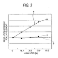
  • FIG.3 is a diagram showing a relationship between an axial load and a revolution speed of each rolling element;
  • FIG. 4 is a diagram showing a relationship between a speed ratio between a rotation speed of a rotary ring and a revolution speed of respective rolling elements and an acceleration (yaw rate, steering, steering effect); and
  • FIG.5 is a sectional view showing an example of the conventional configurations.
  • In above Figures, a reference symbol 1 (1a) denotes a hub, 2 (2a) rotary-side flange, 3 inner ring raceway, 4 (4a) outer ring, 5 (5a) knuckle, 6 (6a) stationary-side flange, 7 outer ring raceway, 8 ball, 9 bolt, 10 threaded hole, 11 load sensor, 12 hub main body, 13 inner ring, 14 spline hole, 15 constant velocity joint, 16 spline shaft, 17 nut, 18 housing, 19 bolt, 20 disk, 21 wheel, 22 stud, 23 nut, 24 revolution speed sensor, 25 rotation speed sensor, 26 fitting hole, 27 cage, 28 encoder, 29 space, and 30 combined sealing ring.
    <Best Mode for Carrying Out the Invention>
    FIG.1 and FIG.2 show an example of embodiments of the present invention. This example shows the case where the present invention is applied to the rolling bearing unit used to support the driving wheel of the car (the rear wheel of the FR car, the RR car and the MD car, the front wheel of the FF car, and all wheels of the 4WD car). A hub 1a serving as the rotary ring and corresponding to the inner ring equivalent member is constructed by fitting/fixing an inner ring 13 onto an inner end portion of a hub main body 12. A rotary-side flange 2a for supporting the wheel is fixed to an outer peripheral surface of the outer end portion of the hub main body 12. Also, the inner ring raceways 3, 3 are formed on the outer peripheral surface of the middle portion of the hub main body 12 and the outer peripheral surface of the inner ring 13 respectively, so that double row angular contact inner ring raceways are provided on the outer peripheral surface of the hub 1a.
    Meanwhile, a stationary-side flange 6a for supporting/fixing an outer ring 4a onto a knuckle 5a, which constitutes the suspension system, is fixed to an outer peripheral surface of the outer ring 4a, which is arranged around the hub 1a concentrically with the hub 1a and serves as the stationary ring. Also, the double row outer ring raceways 7, 7 are formed on an inner peripheral surface of the outer ring 4a. Then, a plurality of balls 8, 8 acting as the rolling element respectively are provided rotatably between the outer ring raceways 7, 7 and the inner ring raceways 3, 3 respectively, so that the hub 1a is supported rotatably on the inner diameter side of the outer ring 4a. In this case, respective balls 8, 8 are made of a magnetic metal such as high carbon chromium bearing steels like SUJ2.
    In operation of the above rolling bearing unit, a spline shaft 16 attached to a constant velocity joint 15 is inserted into a spline hole 14 formed in the middle portion of the hub main body 12. The hub 1a is held between a nut 17 screwed into the top end portion of the spline shaft 16 and a housing 18 of the constant velocity joint 15 from both sides in the axial direction. Also, the stationary-side flange 6a is supported/fixed to the knuckle 5a by a plurality of bolts 19. Also, a brake disk 20 and a wheel 21 of the wheel are supported/fixed to the rotary-side flange 2a by plural studs 22 and nuts 23.
    A revolution speed sensor 24 and a rotation speed sensor 25 are provided to such rolling bearing unit or the knuckle 5a. This revolution speed sensor 24 is used to measure a revolution speed of the balls 8, 8 in the outer row in the axial direction. The revolution speed sensor 24 is fitted into a fitting hole 26. This fitting hole 26 is formed on a part of the outer ring 4a between the double row outer ring raceways 7, 7 to pass through the outer ring 4a in the radial direction. In other words, the revolution speed sensor 24 is provided to pass through this fitting hole 26 from the outside to the inside in the radial direction, and a sensing portion provided to a top end portion of the revolution speed sensor 24 is opposed to the balls 8, 8 in the outer row or a cage 27 that holds these balls 8, 8 therein.
    Also, an encoder 28 is fitted/fitted on an outer peripheral surface of the inner end portion of the inner ring 13, and a sensing portion provided to a top end portion of the rotation speed sensor 25 supported to the knuckle 5a is opposed to a sensed surface of the encoder 28. As this encoder 28, various configurations utilized in the prior art to derive control signals in the ABS or the TCS by sensing the rotation speed of the wheel may be employed. For example, the encoder 28 can be affixed to an inner surface of a slinger that constitutes a combined sealing ring 30. This combined sealing ring 30 is used to seal an inner end opening portion of a space 29 in which the balls 8, 8 are provided. As the encoder 28 used in this case, preferably the encoder made of the multipolar magnet, on the inner surface of which the N pole and the S pole are arranged alternately. However, the encoder made simply of magnetic material, or the encoder whose optical characteristics are changed alternately at equal intervals along the circumferential direction (when combined with an optical rotation sensor) may be employed.
    Also, as the revolution speed sensor 24 and the rotation speed sensor 25 both being the sensor to sense the rotation speed sensor, the magnetic rotation sensor can be preferably used. Also, as the magnetic rotation sensor, the active rotation sensor into which the magnetic sensing element such as the Hall element, the Hall IC, the magnetoresistive element, the MI element, or the like is incorporated can be preferably used. In constructing the active rotation sensor including such magnetic sensing element, for example, one side surface of the magnetic sensing element is brought into touch with one end surface of a permanent magnet in the magnetizing direction directly or via a stator made of the magnetic material (in the case where the encoder made of the magnetic material is used), and then the other side surface of the magnetic sensing element is opposed to the balls 8, 8 (in the case of the revolution speed sensor 24) or a sensed surface of the encoder 28 (the rotation speed sensor 25) directly or via the stator made of the magnetic material. In case the encoder made of the magnetic material is used, the permanent magnet on the sensor side is not needed.
    For example, when the revolution speed sensor 24 used to sense the revolution speed of the balls 8, 8 is constructed as described above, the characteristic of the magnetic sensing element constituting the revolution speed sensor 24 is changed according to the revolution speed of the balls 8, 8. More particularly, an amount of magnetic flux flowing through the magnetic sensing element is increased the moment the ball 8 made of the magnetic material is positioned in close vicinity of the sensed surface of the revolution speed sensor 24, while an amount of magnetic flux flowing through the magnetic sensing element is decreased the moment the sensed surface opposes to the portion between the adjacent balls 8, 8 in the circumferential direction. An amount of magnetic flux flowing through the magnetic sensing element is changed in this manner, and a frequency at which the characteristic of the magnetic sensing element is changed is in proportion to the revolution speed of the balls 8, 8. Therefore, the revolution speed can be derived based on the sensed signal of the revolution speed sensor 24 in which the magnetic sensing element is built. In this case, this sensed signal is fed into a controller in which a calculator (not shown) is built.
    In order to sense the revolution speed of the balls 8, 8 based on the above mechanism, these balls 8, 8 should be made of the magnetic material. Accordingly, when the balls made of the nonmagnetic material such as ceramics, or the like are used as these balls 8, 8, it is necessary to use the optical sensor as the revolution speed sensor 24. However, the grease to lubricate the rolling contact portion is often sealed in the space 29 in which the sensing portion of the revolution speed sensor 24 is inserted. In such case, a light reflection cannot be effectively conducted. In light of these circumstances, it is preferable that the balls made of the magnetic material should be used as the balls 8, 8 and also the sensor into which the magnetic sensing element is incorporated should be used as the revolution speed sensor 24.
    As described above, in case the revolution speed of the balls 8, 8 is measured directly by the revolution speed sensor 24, it is preferable that the cage made of the nonmagnetic material such as a synthetic resin, or the like should be used as the cage 27 that holds these balls 8, 8 therein. When the cage made of the magnetic material is used, the magnetic flux flowing through between the balls 8, 8 and the sensing portion of the revolution speed sensor 24 is shut off, so that it is impossible to measure the exact revolution speed. Conversely, the revolution speed of the balls 8, 8 can be measured precisely by using the cage 27 made of the nonmagnetic material. Here, the cage 27 may be made of a nonmagnetic metal such as a copper-based alloy, or the like, but it is more preferable that the cage should be made of the synthetic resin because such cage is light in weight and such cage is more hard to shut off the magnetic flux. For instance, because the austenite-based stainless steel that is normally known as the nonmagnetic metal has still a minute magnetism, the cage made of such stainless steel is disadvantageous in an aspect that the revolution speed should be measured exactly.
    Also, since the cage 27 is rotated together with the balls 8, 8 according to the revolution of the balls 8, 8, this revolution speed of the balls 8, 8 can be measured as the rotation speed of the cage 27. In case this revolution speed is measured as the rotation speed of the cage 27, the sensing portion of the revolution speed sensor 24 is faced to the sensed portion provided to a part of the cage 27. In this case, when the cage 27 is made of the magnetic material, the sensed portion can be prepared by arranging an unevenness alternately on a part of the cage 27 at an equal interval in the circumferential direction. Also, when the cage 27 is made of the nonmagnetic material such as the synthetic resin, or the like, such as structure can be preferably employed that, like the encoder 28, the multipolar magnet on the side surface of which the N pole and the S pole are arranged alternately is affixed to a part of the cage 27.
    Also, as the revolution speed sensor 24 and the rotation speed sensor 25, the passive magnetic rotation sensor constructed by winding up a coil around the pole piece made of the magnetic material can be employed. In this case, a voltage of the sensed signal of the passive magnetic rotation sensor is reduced when the rotation speed is lowered. In the case of the load measuring unit for the rolling bearing unit as the object of the present invention, since the principal object is to achieve the running stability during the high-speed running of the mobile body, it is seldom handled as an issue that the voltage of the sensed signal is lowered at the time of low speed rotation. However, if the fulfillment of the high-precision control during the low speed running is also intended, it is preferable to employ the active rotation sensor into which the magnetic sensing element and the permanent magnet, as described above.
    Also, in either case the active type or the passive type is as the rotation sensor, it is preferable that sensor constituent parts such as the magnetic sensing element such as the Hall element and the permanent magnet, the pole piece, the coil, etc., except the sensing surface provided to the top end portion, should be molded in the nonmagnetic material such as the synthetic resin, or the like. The rotation sensor constructed by molding the sensor constituent parts in the synthetic resin in this manner is opposed to the sensed portion, i.e., the balls 8,8 or the cage 27 in the case of the revolution speed sensor 24 or the encoder 28 in the case of the rotation speed sensor 25. In the illustrated example, the revolution speed sensor 24 is opposed to the balls 8, 8 in the outer side or the cage 27 holding these balls 8, 8 therein to sense the revolution speed of the balls 8, 8. Also, in the illustrated example, the revolution speed sensor 24 is opposed to the balls 8, 8 or the cage 27 in the axial direction, but such revolution speed sensor 24 can be positioned in the radial direction within a limit in which the interference between such sensor and the rolling contact portions of the balls 8, 8 on the outer ring raceway 7 can be prevented.
    The load measuring unit for the rolling bearing unit of the present invention constructed as above can sense the axial load, which acts between the wheel 21 constituting the wheel and the knuckle 5a and is applied to the rolling bearing unit, by sensing the revolution speed of the balls 8, 8 directly or via the cage 27. That is, when the axial load is loaded onto the rolling bearing unit as the double row angular contact ball bearing, a contact angle of the balls 8, 8 is changed. For example, as indicated with an arrow α in FIG.1, when the axial load is applied inwardly, the contact angle of the balls 8, 8 on the outer side (the left side in FIG.1) is increased. As well known in the technical field of the rolling bearing, the revolution speed of the balls 8, 8 constituting the angular contact ball bearing is changed when the contact angle of the balls 8, 8 is changed. More specifically, in the outer row that supports the axial load, the revolution speed of the balls 8, 8 is accelerated as the axial load is increased. Therefore, the axial load applied to the rolling bearing unit can be sensed if a change of the revolution speed is measured.
    For example, FIG.3 shows a relationship between a magnitude of the axial load and the revolution speed of the balls 8, 8 in the case where the axial load is applied to the back-to- back arrangement type double row rolling bearing unit, which has the configuration shown in FIGS.1 and 2, in the direction indicated with the arrow α. A solid line a in FIG.3 denotes a relationship between the axial load and the revolution speed of the balls 8, 8 in the outer row (the left side in FIG.1), and a broken line b denotes a relationship between the axial load and the revolution speed of the balls 8, 8 in the inner row. Where the radial load is set constant. As apparent from such FIG.3, with regard to the balls 8, 8 in the row on the side that receives the axial load, the magnitude of the axial load and the revolution speed of the balls 8, 8 have an almost proportional relation. Therefore, the axial load acting on the double row rolling bearing unit can be calculated by measuring the revolution speed of the balls 8, 8. Also, as the revolution speed sensor 24 used to measure the revolution speed, the inexpensive speed sensor, which is widely used to get the control signal in the ABS or the TCS in the prior art, can be employed. For this reason, the unit for measuring the axial load applied to the double row rolling bearing unit can be constructed inexpensively. It is preferable that the relationship used to detect the axial load and indicated by the solid line a in FIG.3 should be detected previously experimentally or by a calculation and then input into a calculator that is used to calculate the axial load.
    Here, such a situation may be considered that, in case the vehicle, e.g., various carrier cars used in the factory, moves at a constant speed, the rolling bearing unit is used in a state that the rotation speed of the rotary ring is always kept constant. In such case, as the rotation sensor used to calculate the axial load, it is enough to provide only the revolution speed sensor 24. On the contrary, like the illustrated example, in the case of the double row rolling bearing unit used to support the wheel of the car, the rotation speed of the hub 1a as the rotary ring is changed in use. Therefore, in the illustrated example, the rotation speed sensor 25 in addition to the revolution speed sensor 24 is provided to sense the rotation speed of the hub 1a. Then, the axial load is calculated based on the rotation speed of the hub 1a sensed by the rotation speed sensor 25 and the revolution speed of the balls 8, 8 sensed by the revolution speed sensor 24.
    The calculator built in the controller (not shown) first calculates a speed ratio of the revolution speed to the rotation speed (=the revolution speed of the balls 8, 8/the rotation speed of the hub 1a), based on a signal representing the revolution speed, which is fed from the revolution speed sensor 24, and a signal representing the rotation speed of the hub 1a, which is fed from the rotation speed sensor 25. Then, a change of the revolution speed of the balls 8, 8 is calculated based on a change of the speed ratio. In this fashion, if a change of the revolution speed is calculated based on the speed ratio and then the axial load applied to the double row rolling bearing unit is calculated based on this change of the revolution speed, the axial load can be calculated exactly even though the rotation speed of the hub 1a is changed. Here, it is preferable that a relationship between the speed ratio and the axial load should be derived previously experimentally or by a calculation and should be input into the calculator used to calculate the axial load.
    Also, in case the present invention is embodied by the rolling bearing unit that is used to support the wheel of the mobile body such as the car, the railway vehicle, or the like, it is preferable that an acceleration sensor (not shown) should be provided separately and then an acceleration generated based on a centrifugal force at the time of changing the route (at the time of turning) should be sensed by this acceleration sensor. In detail, in the case of the mobile body such as the car, the railway vehicle, or the like, merely the radial load acts on the rolling bearing unit at the time of straight running except special situations such as the running in a strong wind, the running on an inclined plane, or the like, but the axial load except a preload seldom acts on such bearing unit. In contrast, when the mobile body changes its route, a lateral force acts on this mobile body based on a centrifugal force, and then the axial load acts on the rolling bearing unit based on this force. Accordingly, the axial load hardly acts on the rolling bearing unit when a measured value of the acceleration sensor is substantially zero, while the axial load acting on the rolling bearing unit is increased when a measured value of the acceleration sensor is large.
    FIG.4 shows a relationship between the speed ratio and the measured value of the acceleration sensor. A solid line A in FIG.4 denotes a relationship between the speed ratio and a time, and a broken line B denotes a relationship between the measured value of the acceleration sensor and a time. Also, FIG.4 shows the situation that the mobile body that is running straightly changes its route and then such mobile body returns to the straight running once again. As apparent from such FIG. 4, the speed ratio changes in proportion to the measured value of acceleration sensor. If the acceleration generated based on the centrifugal force is measured by utilizing such relationship and then the axial load is calculated on the basis of the speed ratio obtained when this acceleration is less than a certain value, the axial load can be derived more precisely. In other words, it may be considered that the axial load is almost zero in a condition that the acceleration is less than a certain value (almost zero). Therefore, the speed ratio in this condition is supposed as the speed ratio obtained when the axial load is zero (reference speed ratio). Then, a difference between the speed ratio and the reference speed ratio is calculated at that time when the acceleration is in excess of the certain value and then the axial load is calculated based on this difference (under the assumption that the axial load that is proportional to the difference is acting), the acceleration can be derived with better precision. If the axial load must be derived precisely even under the special condition such as the running in a strong wind, the running on an inclined plane, or the like, such axial load is corrected by using measured values of a side wind speed indicator, a clinometer, etc. provided separately.
    Here, in case the acceleration sensor is provided, a magnitude of the centrifugal force acting the overall mobile body can be calculated by multiplying the acceleration sensed by the acceleration sensor by a mass of the mobile body. However, it is impossible to sense a magnitude of the axial load acting on the individual unit of a plurality of rolling bearing units that support this mobile body. In contrast, according to the load measuring unit for the rolling bearing unit of the present invention, the magnitude of the axial load acting on the individual unit of the rolling bearing units can be sensed. For this reason, this load measuring unit for the rolling bearing unit makes it possible to execute the control that is applied to ensure the running stability of the mobile body such as the car, the railway vehicle, or the like. Here, when the acceleration sensor is to be provided, such sensor may be built in the rolling bearing unit or such sensor may be incorporated into the interior of the mobile body such as the car, the railway vehicle, or the like. Also, either one or plural acceleration sensors may be provided.
    In the case of the car, the railway vehicle, or the like, the acceleration sensor fitted in the car body may be utilized as the acceleration sensor. Also, in the case of the car, the railway vehicle, or the like, a signal of a yaw rate sensor used to sense the yawing (jolt in the lateral direction) of the car body may be utilized in place of the acceleration sensor. That is, since a yaw rate is substantially proportional to the acceleration in the axial direction, the axial load can be derived exactly by using the yaw rate, as in the case where the sensed signal of the acceleration sensor is utilized.
    As described above, in the case of the mobile body including the railway vehicle, the acceleration sensor (or the yaw rate sensor) is used to sense whether or not the route change has been done (whether such mobile body is in a straight line movement condition or a turning movement condition). If the mobile body is restricted to the car, a steering sensor or a torque sensor for the power steering can be used instead of the acceleration sensor. For example, when the steering angle applied to the turning wheel (normally the front wheel except the special purpose vehicle such as the fork lift) of the car is changed as indicated by the broken line □ in FIG.4, the speed ratio is changed as indicated by the solid line
    Figure 00280001
    in FIG. 4. That is, a relationship between the steering angle and the speed ratio almost coincides with the relationship between the acceleration and the speed ratio described above.
    Therefore, even when the steering angle sensor is provided in lieu of the acceleration sensor (or the raw rate sensor) and then the sensed signal of the steering angle sensor is utilized, the similar effect to the case where the acceleration sensor (or the raw rate sensor) is utilized can be achieved. More particularly, the steering angle applied to the turning wheel is measured by the steering angle sensor, then the axial load is calculated on the basis of the speed ratio obtained when this steering angle is less than a certain value (substantially zero), and then the speed ratio in this condition is assumed as the speed ratio obtained when the axial load is zero (reference speed ratio). Then, when the steering angle exceeds the certain value (the steering angle is substantially applied), a difference between the speed ratio and the reference speed ratio at that point of time is calculated and then the axial load is calculated based on this difference. Thus, the axial load can also be sensed with good precision.
    Also, it can be decided whether or not the steering angle is applied to the turning wheel, based on the sensed signal of the torque sensor that is built in the (electric or hydraulic) power steering used to reduce a force (steering force) required to turn the steering wheel. More particularly, the steering wheel is not turned in the straight line running condition during which no steering angle is applied to the turning wheel, and the torque is never applied to the steering shaft. Thus, the sensed signal of the torque sensor becomes substantially zero. In contrast, the steering wheel is turned in the turning running condition during which the steering angle is applied to the turning wheel, and the torque is applied to the steering shaft. Thus, the speed ratio obtained when the axial load applied to the rolling bearing unit is zero (reference speed ratio), which was obtained by the acceleration sensor (or the raw rate sensor) or the steering angle sensor, can also be obtained by the sensed signal of the torque sensor. Then, when the torque sensor senses the torque after the reference speed ratio is calculated, the axial load is calculated based on the speed ratio at that point of time.
    The sensed values of the acceleration sensor, the steering angle sensor, the torque sensor, and the yaw rate sensor utilized to improve a measuring precision of the axial load, as described above, can be utilized solely or in combination respectively. That is, a compared value is calculated by comparing the sensed values of two sensors or more selected from the above sensors mutually, and then the revolution speed or the speed ratio in a condition that the resultant compared value is below a predetermined value is set as a reference value. Then, when the compared value exceeds the predetermined value, a difference between the revolution speed or the speed ratio in that condition and the reference value is calculated, and the axial load is calculated based on this difference. Thus, a measuring precision of the axial load can be improved.
    In the illustrated example, such an example is shown that the revolution speed sensor 24 is provided only to the balls 8, 8 side in the outer side row whose contact angle is largely changed to generate a large variation of the revolution speed since such balls receive the particularly large axial load during the turning running caused by the route change. On the contrary, if the revolution speed sensor 24 is also provided to the balls 8, 8 side in the inner side row to sense a difference between the revolution speeds of the balls 8, 8 in both the outer and inner side rows, the axial load can be detected with better precision. In addition, the axial load acting in the opposite direction (outwardly) to the illustrated example can also be detected.
    Also, the signal representing the revolution speed of the balls 8, 8, that the revolution speed sensor 24 senses, and the signal representing the rotation speed of the hub 1a, that the rotation speed sensor 25 senses, may be processed by a hardware such as an analogue circuit, or the like or may be processed based on a software by using a microcomputer, or the like.
    Also, in the illustrated example, the case where the present invention is applied to the double row angular contact rolling bearing unit used to support the wheel of the car is shown. But the present invention can also be applied to the normal single row deep groove ball bearing or the tapered roller bearing. Also, the present invention can be applied to the bearing unit in which the normal single row rolling bearings, in addition to the duplex rolling bearing. Also, when the present invention is to be applied to the double row angular contact rolling bearing unit used to support the wheel of the car, the present invention can be applied to the so-called third-generation hub unit, in which the inner ring raceway on the outer side is formed on the outer peripheral surface of the middle portion of the hub main body, as shown in FIG.1. In other words, the present invention can also be applied to the so-called second-generation hub unit, in which a pair of inner rings are fitted/fixed onto the middle portion to the inner end portion of the hub main body, and the so-called first-generation hub unit, in which a pair of inner rings are fitted/fixed onto the middle portion to the inner end portion of the hub main body and also the outer ring whose outer peripheral surface is formed as a simple cylindrical shape is fitted/supported into the supporting hole of the knuckle. Alternately, the present invention can also be applied to the structure in which a pair of rolling bearings constructed as the single row type respectively are provided between the outer peripheral surface of the middle portion to the inner end portion of the hub main body and the inner peripheral surface of the supporting hole of the knuckle.
    In addition, it may be considered that the revolution speed of respective rolling elements and the speed ratio in the condition that the axial load is zero are different owing to a variation in a machining accuracy (a variation in an initial contact angle) of individual rolling bearing units. Further, there is a possibility that the revolution speed and the speed ratio in the condition that the axial load is zero are changed owing to a minute deformation in respective portions dependent on the use. Therefore, if the speed ratio in the condition that the axial load is zero, which is decided as described above (based on the signals of the acceleration sensor, the steering angle sensor, the torque sensor, the yaw rate sensor, etc.), is stored in the controller as the initial set value, and then such speed ratio is learned (updated) continuously, it can be continued from the first until a long term has elapsed that the axial load is detected precisely.
    The present invention is explained in detail with reference to particular embodiments, but it is apparent for the person skilled in the art that various variations and modifications can be applied without departing a spirit and a scope of the present invention.
    This application was filed based on Japanese Patent Application (Patent Application No.2003-33614) filed on February 12, 2003 and Japanese Patent Application (Patent Application No.2003-120072) filed on April 24, 2003, and the contents thereof are incorporated herein by the reference.
    <Industrial Applicability>
    As described above, the load measuring unit for the rolling bearing unit and the load measuring rolling bearing unit according to the present invention are valuable for the rolling bearing unit used to support the wheel of the mobile body such as the car, the railway vehicle, various carrier cars, or the like, for example.

    Claims (21)

    1. A load measuring unit for a rolling bearing unit, comprising:
      a stationary ring not rotated in use;
      a rotary ring arranged concentrically with the stationary ring, for rotating in use;
      a plurality of rolling elements provided rollably between a stationary-side raceway and a rotary-side raceway that are formed in mutually opposing positions of the stationary ring and the rotary ring;
      a revolution speed sensor for sensing a revolution speed of the rolling elements; and
      a calculator for calculating an axial load applied between the stationary ring and the rotary ring based on a sensed signal fed from the revolution speed sensor.
    2. A load measuring unit for a rolling bearing unit, according to claim 1, wherein one raceway ring out of the stationary ring and the rotary ring is an outer ring equivalent member, the other raceway ring is an inner ring equivalent member, the rolling elements are balls, and a contact angle of back-to-back arrangement type is applied to the balls that are provided in plural between double row angular contact inner ring raceways formed on an outer peripheral surface of the inner-ring equivalent member and double row angular contact outer ring raceways formed on an inner peripheral surface of the outer ring equivalent member respectively.
    3. A load measuring unit for a rolling bearing unit, according to any one of claims 1 and 2, wherein the revolution speed of the rolling elements is measured directly.
    4. A load measuring unit for a rolling bearing unit, according to any one of claims 1 and 2, wherein the revolution speed of the rolling elements is measured as a rotation speed of a cage that holds the rolling elements therein.
    5. A load measuring unit for a rolling bearing unit, according to any one of claims 1 to 4, further comprising:
      a rotation speed sensor for sensing a rotation speed of the rotary ring;
         wherein the calculator calculates the axial load applied between the stationary ring and the rotary ring, based on a sensed signal fed from the rotation speed sensor and a sensed signal fed from the revolution speed sensor.
    6. A load measuring unit for a rolling bearing unit, according to claim 5, wherein the axial load applied between the stationary ring and the rotary ring is calculated based on a speed ratio that is a ratio between the revolution speed of the rolling elements and the rotation speed of the rotary ring.
    7. A load measuring unit for a rolling bearing unit, according to any one of claims 1 to 6, further comprising:
      an acceleration sensor for sensing an acceleration in an axial direction;
         wherein the calculator calculates the axial load applied between the stationary ring and the rotary ring based on the revolution speed or the speed ratio in a state that the acceleration sensed by the acceleration sensor exceeds the predetermined value with respect to the revolution speed or the speed ratio in a state that the acceleration sensed by the acceleration sensor is below a predetermined value.
    8. A load measuring unit for a rolling bearing unit, according to claim 7, wherein the acceleration sensor is fitted to a portion except constituent members of the rolling bearing unit.
    9. A load measuring unit for a rolling bearing unit, according to claim 7, wherein the acceleration sensor is fitted to the constituent members of the rolling bearing unit.
    10. A load measuring unit for a rolling bearing unit, according to any one of claims 1 to 6, wherein the rolling bearing unit is used to support a wheel of a car, and
         further comprising:
      a steering angle sensor for sensing a value that is proportional to a steering angle applied to a turning wheel of the car;
         wherein the calculator calculates the axial load applied between the stationary ring and the rotary ring based on the revolution speed or the speed ratio in a state that the steering angle sensed by the steering angle sensor exceeds the predetermined value with respect to the revolution speed or the speed ratio in a state that the steering angle sensed by the steering angle sensor is below a predetermined value.
    11. A load measuring unit for a rolling bearing unit, according to any one of claims 1 to 6, wherein the rolling bearing unit is used to support a wheel of a car, and
         further comprising:
      a torque sensor for sensing a steering force that a driver applies to a steering shaft by turning a steering wheel;
         wherein the calculator calculates the axial load applied between the stationary ring and the rotary ring based on the revolution speed or the speed ratio in a state that the steering force sensed by the torque sensor exceeds the predetermined value with respect to the revolution speed or the speed ratio in a state that the steering force sensed by the torque sensor is below a predetermined value.
    12. A load measuring unit for a rolling bearing unit, according to any one of claims 1 to 6, wherein the rolling bearing unit is used to support a wheel of a vehicle, and
         further comprising:
      a yaw rate sensor for sensing a yaw rate applied to a car body of the vehicle;
         wherein the calculator calculates the axial load applied between the stationary ring and the rotary ring based on the revolution speed or the speed ratio in a state that the yaw rate sensed by the yaw rate exceeds the predetermined value with respect to the revolution speed or the speed ratio in a state that the yaw rate sensed by the yaw rate sensor is below a predetermined value.
    13. A load measuring unit for a rolling bearing unit, according to claim 12, wherein the yaw rate sensor is fitted to a portion except constituent members of the rolling bearing unit.
    14. A load measuring unit for a rolling bearing unit, according to claim 12, wherein the yaw rate sensor is fitted to the constituent members of the rolling bearing unit.
    15. A load measuring unit for a rolling bearing unit, according to any one of claims 1 to 10, wherein the rolling bearing unit is used to support the wheel of the car, and
         further comprising:
      a steering angle sensor sensing a value that is proportional to a steering angle applied to a turning wheel of the car; and
      an acceleration sensor for sensing an acceleration in an axial direction;
         wherein the calculator compares the acceleration sensed by the acceleration sensor in the axial direction with the steering angle sensed by the steering angle sensor, and then calculates the axial load applied between the stationary ring and the rotary ring based on the revolution speed or the speed ratio in a state that a resultant compared value exceeds a predetermined value.
    16. A load measuring unit for a rolling bearing unit, according to any one of claims 1 to 9 and claim 11, wherein the rolling bearing unit is used to support the wheel of the car, and
         further comprising:
      a torque sensor for sensing a steering force that a driver applies to a steering shaft by turning a steering wheel; and
      an acceleration sensor for sensing an acceleration in an axial direction;
         wherein the calculator compares the acceleration sensed by the acceleration sensor in the axial direction with the steering force sensed by the torque sensor, and then calculates the axial load applied between the stationary ring and the rotary ring based on the revolution speed or the speed ratio in a state that a resultant compared value exceeds a predetermined value.
    17. A load measuring unit for a rolling bearing unit, comprising:
      a stationary ring not rotated in use;
      a rotary ring arranged concentrically with the stationary ring, for rotating in use;
      a rolling element provided rollably in plural every row between a stationary-side raceway and a rotary-side raceway that are formed in mutually opposing positions of the stationary ring and the rotary ring in double rows respectively, in a state that directions of contact angles are set oppositely mutually between both rows;
      a pair of revolution speed sensors for sensing a revolution speed of the rolling elements on both rows; and
      a calculator for calculating an axial load applied between the stationary ring and the rotary ring, based on a sensed signal fed from the revolution speed sensors.
    18. A load measuring unit for a rolling bearing unit, according to claim 17, wherein the calculator calculates the axial load applied between the stationary ring and the rotary ring, based on a difference between the revolution speeds of the rolling elements in both rows.
    19. A load measuring unit for a rolling bearing unit, according to claim 18, further comprising:
      a rotation speed sensor for sensing rotation speed of the rotary ring;
         wherein the calculator calculates the axial load applied between the stationary ring and the rotary ring based on a ratio between the rotation speed of the rotary ring, which is derived based on a sensed signal of the rotation speed sensor, and the difference between the revolution speeds of the rolling elements in both rows.
    20. A load measuring rolling bearing unit, comprising:
      a stationary ring not rotated in use;
      a rotary ring arranged concentrically with the stationary ring, for rotating in use;
      a plurality of rolling elements provided rollably between a stationary-side raceway and a rotary-side raceway that are formed in mutually opposing positions of the stationary ring and the rotary ring; and
      a revolution speed sensor for sensing a revolution speed of the rolling elements.
    21. A load measuring rolling bearing unit, according to claim 20, further comprising:
      a calculator for calculating an axial load applied between the stationary ring and the rotary ring, based on a sensed signal fed from the revolution speed sensor.
    EP04708026A 2003-02-12 2004-02-04 Load-measuring device for rolling bearing unit and rolling bearing unit for load measurement Ceased EP1593948A4 (en)

    Applications Claiming Priority (5)

    Application Number Priority Date Filing Date Title
    JP2003033614 2003-02-12
    JP2003033614 2003-02-12
    JP2003120072 2003-04-24
    JP2003120072A JP4433688B2 (en) 2003-02-12 2003-04-24 Load measuring device for rolling bearing unit and rolling bearing unit for load measurement
    PCT/JP2004/001104 WO2004072598A1 (en) 2003-02-12 2004-02-04 Load-measuring device for rolling bearing unit and rolling bearing unit for load measurement

    Publications (2)

    Publication Number Publication Date
    EP1593948A1 true EP1593948A1 (en) 2005-11-09
    EP1593948A4 EP1593948A4 (en) 2006-10-04

    Family

    ID=32871167

    Family Applications (1)

    Application Number Title Priority Date Filing Date
    EP04708026A Ceased EP1593948A4 (en) 2003-02-12 2004-02-04 Load-measuring device for rolling bearing unit and rolling bearing unit for load measurement

    Country Status (6)

    Country Link
    US (1) US7212927B2 (en)
    EP (1) EP1593948A4 (en)
    JP (1) JP4433688B2 (en)
    KR (2) KR20070106586A (en)
    CN (1) CN1748132B (en)
    WO (1) WO2004072598A1 (en)

    Cited By (4)

    * Cited by examiner, † Cited by third party
    Publication number Priority date Publication date Assignee Title
    EP2184182A1 (en) * 2007-07-31 2010-05-12 NTN Corporation Sensor-equipped bearing for wheel
    US7780357B2 (en) * 2005-02-01 2010-08-24 The Timken Company Bearing with cage-mounted sensors
    US8523446B2 (en) 2007-07-31 2013-09-03 Ntn Corporation Sensor equipped wheel support bearing assembly
    DE102022118500A1 (en) 2022-07-25 2024-01-25 Schaeffler Technologies AG & Co. KG Rolling bearings with integrated angle measuring system

    Families Citing this family (25)

    * Cited by examiner, † Cited by third party
    Publication number Priority date Publication date Assignee Title
    WO2005023614A2 (en) * 2003-09-03 2005-03-17 Nsk Ltd. Stability control apparatus and load mesuring instrument for wheel supporting rolling bearing unit
    JP4543643B2 (en) 2003-09-12 2010-09-15 日本精工株式会社 Load measuring device for rolling bearing units
    JP2005199882A (en) * 2004-01-16 2005-07-28 Nsk Ltd Traveling condition stabilizer for vehicle
    US20060245677A1 (en) * 2005-04-28 2006-11-02 Nsk Corporation Device for determining axial force, bearing unit having a device for determining axial force, and method determining axial force
    JP4710455B2 (en) * 2005-07-15 2011-06-29 日本精工株式会社 Abnormality diagnosis device for axle support device of railway vehicle
    US7819026B2 (en) * 2005-09-06 2010-10-26 Ntn Corporation Sensor-equipped wheel support bearing assembly
    JP5089041B2 (en) * 2005-12-08 2012-12-05 Ntn株式会社 Wheel bearing with sensor
    EP1962073B1 (en) * 2005-12-08 2019-05-22 NTN Corporation Sensor-equipped bearing for wheel
    EP2006652B1 (en) * 2006-03-08 2013-06-19 NTN Corporation Bearing for wheel with sensor
    US8439568B2 (en) * 2006-08-25 2013-05-14 Ntn Corporation Wheel support bearing assembly equipped with sensor
    EP2208034A1 (en) * 2007-10-22 2010-07-21 The Timken Company Drive torque sensing wheel end
    DE102007055219A1 (en) * 2007-11-19 2009-05-20 Magna Powertrain Ag & Co Kg Torque determining device for motor vehicle, has selection position arranged in such manner that sensors detect angle position and/or rotating motion of transmitter element, where one sensor is adjacent to another sensor
    JP5160468B2 (en) * 2009-02-16 2013-03-13 日立建機株式会社 Construction machine load measuring device
    JP2012202791A (en) * 2011-03-25 2012-10-22 Jatco Ltd Rotation state detecting device
    JP5820842B2 (en) * 2013-05-08 2015-11-24 富士重工業株式会社 Wheel reaction force detection device
    CN103267641B (en) * 2013-06-18 2015-04-22 青岛泰德汽车轴承股份有限公司 Temperature-rise test device and method for sealed double-row angular contact ball bearings
    CN103292998B (en) * 2013-07-01 2016-05-04 燕山大学 Single oscillation driven member Double-disk cam oscillating bearing high-speed tester (HST)
    CN104034366B (en) * 2014-03-28 2017-02-22 江阴万讯自控设备有限公司 Electric actuator detection device and detection method thereof
    JP6550219B2 (en) * 2014-08-06 2019-07-24 Ntn株式会社 Wheel bearing device
    CN105522529A (en) * 2016-01-14 2016-04-27 苏州成科自控设备有限公司 Encoder installing tool
    ITUA20161867A1 (en) * 2016-03-21 2017-09-21 Nuovo Pignone Tecnologie Srl METHOD FOR MONITORING AN AXIAL PUSH ON A ROLLING BEARING AND MACHINE EQUIPPED WITH A MONITORING SYSTEM OF SUCH A PUSH-AXIS
    JP6786373B2 (en) * 2016-12-14 2020-11-18 Ntn株式会社 Rolling bearing with rotation sensor
    CN109333439A (en) * 2018-11-29 2019-02-15 奇瑞商用车(安徽)有限公司 For measuring the simple accessory and method of adjustment of rear axle hub bearing staring torque
    JP7388051B2 (en) * 2019-08-28 2023-11-29 日本精工株式会社 Rolling bearing condition monitoring method and rolling bearing condition monitoring system
    CN110906885B (en) * 2019-12-24 2021-03-30 洛阳恒锐测控科技有限公司 High-speed high-precision contact angle measurement method for angular contact bearing

    Citations (4)

    * Cited by examiner, † Cited by third party
    Publication number Priority date Publication date Assignee Title
    US4161877A (en) * 1976-09-18 1979-07-24 Motoren-Und Turbinen-Union Munchen Gmbh Method for the determination of the axial thrust of roller bearings
    US5140849A (en) * 1990-07-30 1992-08-25 Agency Of Industrial Science And Technology Rolling bearing with a sensor unit
    US5952587A (en) * 1998-08-06 1999-09-14 The Torrington Company Imbedded bearing life and load monitor
    US20020092360A1 (en) * 2000-04-10 2002-07-18 The Timken Company Bearing assembly with sensors for monitoring loads

    Family Cites Families (9)

    * Cited by examiner, † Cited by third party
    Publication number Priority date Publication date Assignee Title
    JPS5594541U (en) 1978-12-21 1980-06-30
    JPS62218832A (en) 1986-03-19 1987-09-26 Mitsubishi Electric Corp Thrust load detector for rotary machine
    JPS63176761A (en) * 1987-01-14 1988-07-21 Koyo Seiko Co Ltd Bearing unit of automobile wheel
    FR2653192B1 (en) 1989-10-16 1995-01-20 Roulements Soc Nouvelle BEARING COMPRISING A SPEED DETECTION DEVICE.
    SE8904082D0 (en) 1989-12-04 1989-12-04 Skf Nova Ab hub unit
    JP2913913B2 (en) 1991-06-12 1999-06-28 日本精工株式会社 Method and apparatus for measuring the contact angle of a rolling bearing
    JPH1172501A (en) * 1997-06-27 1999-03-16 Nippon Seiko Kk Roller bearing unit with rotational speed sensor and assembling method thereof
    JP2001021577A (en) * 1999-07-12 2001-01-26 Nsk Ltd Rolling bearing unit for supporting wheel
    JP2002323056A (en) * 2001-04-24 2002-11-08 Ntn Corp Wheel bearing device

    Patent Citations (4)

    * Cited by examiner, † Cited by third party
    Publication number Priority date Publication date Assignee Title
    US4161877A (en) * 1976-09-18 1979-07-24 Motoren-Und Turbinen-Union Munchen Gmbh Method for the determination of the axial thrust of roller bearings
    US5140849A (en) * 1990-07-30 1992-08-25 Agency Of Industrial Science And Technology Rolling bearing with a sensor unit
    US5952587A (en) * 1998-08-06 1999-09-14 The Torrington Company Imbedded bearing life and load monitor
    US20020092360A1 (en) * 2000-04-10 2002-07-18 The Timken Company Bearing assembly with sensors for monitoring loads

    Non-Patent Citations (1)

    * Cited by examiner, † Cited by third party
    Title
    See also references of WO2004072598A1 *

    Cited By (7)

    * Cited by examiner, † Cited by third party
    Publication number Priority date Publication date Assignee Title
    US7780357B2 (en) * 2005-02-01 2010-08-24 The Timken Company Bearing with cage-mounted sensors
    EP2184182A1 (en) * 2007-07-31 2010-05-12 NTN Corporation Sensor-equipped bearing for wheel
    EP2184182A4 (en) * 2007-07-31 2012-08-29 Ntn Toyo Bearing Co Ltd Sensor-equipped bearing for wheel
    US8434947B2 (en) 2007-07-31 2013-05-07 Ntn Corporation Sensor-equipped bearing for wheel
    US8523446B2 (en) 2007-07-31 2013-09-03 Ntn Corporation Sensor equipped wheel support bearing assembly
    EP2184182B1 (en) * 2007-07-31 2016-11-02 NTN Corporation Sensor-equipped bearing for wheel
    DE102022118500A1 (en) 2022-07-25 2024-01-25 Schaeffler Technologies AG & Co. KG Rolling bearings with integrated angle measuring system

    Also Published As

    Publication number Publication date
    EP1593948A4 (en) 2006-10-04
    CN1748132A (en) 2006-03-15
    WO2004072598A1 (en) 2004-08-26
    KR20050098934A (en) 2005-10-12
    US20060155507A1 (en) 2006-07-13
    JP2004294414A (en) 2004-10-21
    KR100859958B1 (en) 2008-09-24
    KR20070106586A (en) 2007-11-01
    US7212927B2 (en) 2007-05-01
    CN1748132B (en) 2010-06-23
    JP4433688B2 (en) 2010-03-17

    Similar Documents

    Publication Publication Date Title
    US7212927B2 (en) Load-measuring device for rolling bearing unit and rolling bearing unit for load measurement
    JP4940937B2 (en) Rotating machine state quantity measuring device
    US7819026B2 (en) Sensor-equipped wheel support bearing assembly
    US7216551B2 (en) Rolling bearing unit with sensor
    JP4888074B2 (en) Rolling bearing device for wheels
    JP2005031063A (en) Load measuring device for rolling bearing unit, and rolling bearing unit for measuring load
    JP2007127253A (en) Rolling bearing device with sensor
    JP2006242241A (en) Ball bearing unit
    JP2004340579A (en) Instrument for measuring load of rolling bearing unit, and rolling bearing unit for measuring load
    JP4957412B2 (en) Inspection method for state quantity measuring device of rolling bearing unit
    JP4269669B2 (en) Load measuring device for rolling bearing units
    JP2005180985A (en) Load measuring device for rolling bearing unit
    JP2008292275A (en) Load measuring instrument for rolling bearing unit
    JP2004198210A (en) Load measuring apparatus for rolling bearing unit
    JP2005049159A (en) Hub unit with sensor
    JP2005091073A (en) Rotation speed detector and load measuring instrument for roller bearing unit
    JP2005164253A (en) Load measuring instrument for rolling bearing unit
    JP2005098771A (en) Load-measuring device of rolling bearing unit
    JP4218361B2 (en) Rolling bearing unit with sensor
    JP2005181265A (en) Load measuring device for rolling bearing unit
    JP2005090993A (en) Load measuring device for roller bearing unit
    JP2005114710A (en) Load-measuring instrument for rolling bearing unit
    JP4941140B2 (en) State quantity measuring device for rolling bearing units
    JP2006177834A (en) Rolling bearing unit having sensor
    JP2007199040A (en) Rolling bearing unit with load-measuring device joint-fixed with wheel

    Legal Events

    Date Code Title Description
    PUAI Public reference made under article 153(3) epc to a published international application that has entered the european phase

    Free format text: ORIGINAL CODE: 0009012

    17P Request for examination filed

    Effective date: 20050811

    AK Designated contracting states

    Kind code of ref document: A1

    Designated state(s): AT BE BG CH CY CZ DE DK EE ES FI FR GB GR HU IE IT LI LU MC NL PT RO SE SI SK TR

    AX Request for extension of the european patent

    Extension state: AL LT LV MK

    DAX Request for extension of the european patent (deleted)
    A4 Supplementary search report drawn up and despatched

    Effective date: 20060901

    17Q First examination report despatched

    Effective date: 20101216

    REG Reference to a national code

    Ref country code: DE

    Ref legal event code: R003

    STAA Information on the status of an ep patent application or granted ep patent

    Free format text: STATUS: THE APPLICATION HAS BEEN REFUSED

    18R Application refused

    Effective date: 20170416