EP1593592A2 - A children' s car driven by swiveling operations of a steering wheel - Google Patents
A children' s car driven by swiveling operations of a steering wheel Download PDFInfo
- Publication number
- EP1593592A2 EP1593592A2 EP05004065A EP05004065A EP1593592A2 EP 1593592 A2 EP1593592 A2 EP 1593592A2 EP 05004065 A EP05004065 A EP 05004065A EP 05004065 A EP05004065 A EP 05004065A EP 1593592 A2 EP1593592 A2 EP 1593592A2
- Authority
- EP
- European Patent Office
- Prior art keywords
- car
- children
- wheels
- steering
- steering wheel
- Prior art date
- Legal status (The legal status is an assumption and is not a legal conclusion. Google has not performed a legal analysis and makes no representation as to the accuracy of the status listed.)
- Granted
Links
Images

Classifications
-
- A—HUMAN NECESSITIES
- A63—SPORTS; GAMES; AMUSEMENTS
- A63G—MERRY-GO-ROUNDS; SWINGS; ROCKING-HORSES; CHUTES; SWITCHBACKS; SIMILAR DEVICES FOR PUBLIC AMUSEMENT
- A63G19/00—Toy animals for riding
- A63G19/08—Toy animals for riding made to travel by ratchet-wheels, e.g. by stretching the legs
-
- B—PERFORMING OPERATIONS; TRANSPORTING
- B62—LAND VEHICLES FOR TRAVELLING OTHERWISE THAN ON RAILS
- B62K—CYCLES; CYCLE FRAMES; CYCLE STEERING DEVICES; RIDER-OPERATED TERMINAL CONTROLS SPECIALLY ADAPTED FOR CYCLES; CYCLE AXLE SUSPENSIONS; CYCLE SIDE-CARS, FORECARS, OR THE LIKE
- B62K9/00—Children's cycles
Definitions
- the present invention relates to a children's car that moves forward by swiveling operations of a steering wheel.
- the steering wheel is swiveled repeatedly by a child on the car to cause the car to move forward through successive 'pick and pull' operations of a scraper at the front on a floor or ground.
- children's cars of various types have been known.
- the types of children's car that moves forward in a zigzag pattern by the operation of a steering wheel have their merits and are thus fairly popular as a toy.
- none of the children's cars known are free from room for improvement. When the cars are put into use, problems are encountered leaving room for improvement. A child is apt to act unpredictably.
- the children's car with a crank shaft could also cause a problem, the crank shaft itself becoming a hazard causing point.
- the scraper-type can cause problems as aforementioned, causing damage to the floor and causing difficulty in operating the handle when the friction resistance is considerable. Therefore, whatever type the children's car may be with their own specific features, there is essential need for a safe children's car free from hazards.
- the object of the present invention is to provide a children's car that can move forward by a simple operation with less likelihood of hazards caused by the car's falling.
- the present invention presents the following construction.
- the children's car of the present invention comprises:
- the auxiliary wheels are provided such that there is a certain gap between them and the floor on which the children's car moves, wherein said auxiliary wheels come in contact with the floor when said car body (1) tilts at a certain angle.
- the steering block is in the form of a rectangular parallelepiped.
- the children's car of the present invention by a simple construction of the ratchet wheel and the pawl, only one of the pair of the drive wheels can rotate forward by a turn of the steering wheel. In other words, greater dependability is assured by the employment of simple structure.
- the children's car can be moved forward in a zigzag pattern with simple operations of turning the steering wheel left and right. Because of this, even if the child operates the steering wheel at random, the child can run the car forward easily.
- the children's car of the present invention is provided with auxiliary wheels running at right angle or about right angle with the support axis of the shaft of the drive wheels.
- the children's car is constructed in such a way as to run in a stable condition ensuring the safety of the child. As a result, the child can ride the car around easily without worrying about its own safety and with simple operations of the steering wheel. Besides, if the steering block is in the form of a rectangular parallelepiped, the steering block can be manufactured easily, making it possible to install the pawl to the steering block easily. As a result, the productivity in manufacturing the children's car increased and the manufacturing cost is reduced.
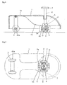
- Figure 1 is a sectional view showing the whole structure of the children's car of the present invention.
- Figure 2 is a bottom view showing the structure of the children's car of the present invention illustrating its drive system.
- the main body of the children's car is a car body 1 having a seat 1a and a footrest 1b.
- the body is usually made in an integral form of plastic material.
- a steering column 6 In the center front portion of the car body, a steering column 6 is provided vertically and rotatably. At the top of the steering column 6, a steering wheel 7 is fixed integrally. A steering block 5, a transmission member, is fixed to the steering column 6. Two shafts 4 are supported to the steering block 5 in a cantilever form with one end of each of the shafts 4 fixed to the steering block 5.
- a pair of drive wheels 2 are rotatably supported to the shafts 4.
- the turning operation of the steering wheel 7 is transmitted to the drive wheels 2 through the steering block 5 and the shafts 4.
- the steering wheel 7 is turned right horizontally (clockwise in Fig. 2)
- the steering block 5 and the shaft 4 also turn horizontally in the same direction, and the turning of the shaft 4 is transmitted to the pair of drive wheels 2.
- a pair of rear wheels 3 are provided rotatably through shafts Xa in such a way that the rear wheels 3 touch the floor or the ground. Therefore, the car body 1 is supported by a pair of front wheels, namely, drive wheels 2 and a pair of rear wheels 3.
- the pair of drive wheels 2 are supported rotatably to the shafts 4 provided on both sides of the steering block 5.
- a ratchet wheel G is integrally fixed to each of the drive wheels 2.
- Each of the drive wheels 2 can rotate independently together with a ratchet wheel G.
- the steering block 5 has a form of a rectangular parallelepiped.
- the rectangular parallelepiped form is advantageous for the steering block 5 because it makes it easier to manufacture it, easier to attach pawls P, increases productivity, and reduces production cost. Nevertheless, the steering block 5 may be made in a different form as long as it can be provided with the shafts 4, the pawls P, and the shafts 4X to be mentioned later.
- the engagement of the pawl P with the ratchet wheel G leads the ratchet wheel G to rotate in one direction only, preventing an inverse rotation and serving a role of a one-direction clutch. Therefore, if one of the drive wheels 2 attempts to rotate forward, the ratchet wheel G also rotates in the same direction, without engagement between the ratchet wheel G and the pawl P, leading one of the drive wheels 2 to rotate forward. However, if the drive wheel 2 attempts to rotate in the inverse direction backwards, the ratchet wheel G engages with the pawl P blocking the inverse rotation. Therefore, under such a circumstance, the drive wheel 2 cannot rotate backwards but remains still in the position in which it is located.
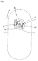
- the car body of the children's car moves forward in a zigzag pattern. For instance, as shown in Fig. 3, if the steering wheel 7 is turned left, the left drive wheel 2L does not rotate because the ratchet wheel G and the pawl P are engaged. On the other hand, the right drive wheel 2R rotates forward in a circular arc motion in the arrow direction according to the turn of the steering wheel 7 without the engagement of the ratchet wheel G with the pawl P. The car body 1 moves forward to the extent that the axial line of the shaft 4 of the drive wheel 2 moved forward in a leftward circular arc motion, that is, to the extent that the right drive wheel 2R rotated forward.
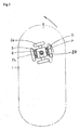
- FIG 4 illustrates the circumstance where the steering wheel 7 is turned right.
- the right drive wheel 2R is locked and does not rotate, but the left drive wheel 2L rotates according to the turn of the steering wheel 7, rotating forward in the arrow direction in a rightward circular arc motion without the engagement of the ratchet wheel G with the pawl P.
- the car body 1 moves forward to the extent that the axial line of the shaft 4 of the drive wheel 2 moved forward in a rightward circular arc motion, that is, to the extent that the left drive wheel 2L rotated forward.
- the car body 1 moves forward if the steering wheel 7 is turned alternately left and right. With the repetition of the alternate turning of the steering wheel 7, the children's car continues to move forward.
- FIG. 5 illustrates said construction of the children's car of the present invention.
- Each of the pair of drive wheels 2 repeats the operation of rotating and stopping alternately, moving the car body 1 forward little by little in a zigzag pattern.
- S-S line in Fig. 5 as a start line, further description is given as follows.
- a right turn of the steering wheel 7 is transmitted to the pair of drive wheels 2 through the steering column 6 and the steering block 5.
- the right drive wheel 2R receives a force to move backward, but is kept still, unable to rotate backward by the engagement of the ratchet wheel with the pawl P.
- the left drive wheel 2L free from the engagement of the ratchet wheel G with the pawl P, rotates forward, as shown with an arrow, in a circular arc motion with the right drive wheel 2R as an axial support point, moving forward to the position indicated as the first step 1S.
- a left turn of the steering wheel 7 is transmitted to the pair of drive wheels 2 through the steering column 6 and the steering block 5.
- the left drive wheel 2L receives a force to move backward, but is kept still, unable to rotate backward by the engagement of the ratchet wheel with the pawl P.
- the right drive wheel 2R free from the engagement of the ratchet wheel G with the pawl P, rotates forward, as shown with an arrow, in a circular arc motion with the left drive wheel 2L as an axial support point, moving forward to the position indicated as the second step 2S.
- the car body 1 moves forward to the positions shown as the third step 3S and the fourth step 4S, and so on, moving forward in a zigzag pattern.
- the child sitting on the seat of the children's car, can move the car forward with a simple operation of the steering wheel 7.
- a shaft 4X is provided with one end of it supported to the steering block 5 in a cantilever form.
- Each of the shafts 4X is provided with an auxiliary wheel 2a for the stability of the car body 1.
- the shafts 4X whose axial lines cross the axial lines of the shafts 4 at right or about right angle, are provided with rotatable auxiliary wheels 2a.
- the auxiliary wheels 2a are not drive wheels but are designed to maintain the car body 1 in a stable condition. The child, riding the children's car, could move his body forward or stand up suddenly, causing the car body 1 to tilt and lose balance.
- the auxiliary wheels 2a in touch with the floor or the ground, support the car body 1.
- the auxiliary wheels 2a under normal condition, are designed to have a slight gap between them and the floor or the ground on which the car runs. In other words, under normal condition, there is a certain distance between the auxiliary wheels 2a and the surface on which the car runs.
- the normal condition here means the condition where a pair of drive wheels 2 and a pair of rear wheels 3 are in touch with the floor or the ground with the children's car supported stable. If the steering wheel 7 is turned and change the direction of the drive wheels 2 through the steering block 5, the direction of the auxiliary wheels 2a also changes accordingly. Under such circumstance as well, if the car body 1 is likely to lose balance, the auxiliary wheels 2a support the car body 1 maintaining its balance.
- the front auxiliary wheel 2a serves to prevent the car body 1 from falling forward. With a certain distance between the auxiliary wheels 2a and the running surface, the auxiliary wheels 2a do not cause hindrance to the children's car running, even if the running surface is somewhat rough with some convex and concave. Furthermore, for instance, if the child turns the steering wheel 7 left or right nearly 90 degrees, conventional children's cars would become very unstable like a children's tricycle. However, the children's car of the present invention, with the auxiliary wheels 2a provided near the sides of the car body 1, support the car body 1 under such circumstances when the car body tilts, by touching the ground and supporting the car body 1. In other words, even if the steering wheel is turned very hard, the drive wheels 2 and the auxiliary wheels 2a keep the front part of the car body 1 stable.
- the child may often operate the steering wheel 7 of the children's car roughly. While operating the steering wheel 7, the child may make sudden, irregular movements. Under such circumstances, the auxiliary wheels 2a can cope with such an unexpected situation and help keep the children's car stable.
- a steering wheel 7 is provided at the front of the car which can be swivelled left and right. By the operation of the steering wheel 7, a pair of drive wheels 2 rotate.
- a steering block 5 which can be steered horizontally either to the left or to the right with a steering wheel 7 and a steering column 6 are provided at the front of the car body 1 provided with a seat 1a and a footrest 1b.
- Two drive wheels 2 each having a ratchet wheel G are provided on both sides of said steering block 5 by a shaft 4.
- a pawl P linked to said steering block 5 preventing inverse rotation of the drive wheels 2.
- An auxiliary wheel 2a is installed each at the front and at the rear of said steering block 5 as a means to stable support the car body 1, thereby enhancing the safety of the child riding the car.
- Rear wheels 3 are installed at the rear of said car body 1 by means of a shaft 4Xa.
Abstract
Description
- The present invention relates to a children's car that moves forward by swiveling operations of a steering wheel.
- In prior arts, a child moved a car in which he was seated by simply kicking the ground backwards alternatingly with his feet, or by pedaling on a crankshaft linked to both front wheels.
- In another conventional version of a children's car, the steering wheel is swiveled repeatedly by a child on the car to cause the car to move forward through successive 'pick and pull' operations of a scraper at the front on a floor or ground.
- In prior arts of a scraper's 'pick and pull' operation, however, it poised a problem of a floor being scratched by the scraper when used indoor and of requiring heavy efforts for swiveling handles due to greater frictional force although swiveling procedure was simple for a child.
- Besides the above, a children's car that moves forward in a zigzag pattern by a swiveling operation of a steering wheel by a riding child is known. (Japanese Utility Model Application No.1989-58939, Publication No. 1990-149395).
- As noted above, children's cars of various types have been known. The types of children's car that moves forward in a zigzag pattern by the operation of a steering wheel have their merits and are thus fairly popular as a toy. However, none of the children's cars known are free from room for improvement. When the cars are put into use, problems are encountered leaving room for improvement. A child is apt to act unpredictably.
- Therefore, despite the fact that the car falls into a category of a toy, it could cause a hazardous situation. For example, children's cars in general are manufactured in light weight. Because of this, if a child stands up from a seat or makes a sudden move forward from the seat, problems can arise. For instance, if the child makes a sudden forceful move forward, the child can slip against the children's car or cause imbalance between the child's body and the children's car, causing the rear portion of the car to be lifted, leading the car to fall forward. As a result, the child could be tossed out of the car and injured depending upon the condition of the floor surface. The types of a children's car that moves forward in a zigzag pattern only by the operation of a steering wheel are liable to such a hazardous situation.
- The children's car with a crank shaft could also cause a problem, the crank shaft itself becoming a hazard causing point. The scraper-type can cause problems as aforementioned, causing damage to the floor and causing difficulty in operating the handle when the friction resistance is considerable. Therefore, whatever type the children's car may be with their own specific features, there is essential need for a safe children's car free from hazards.
- The object of the present invention is to provide a children's car that can move forward by a simple operation with less likelihood of hazards caused by the car's falling.
- To attain the above objectiv, the present invention presents the following construction.
- The children's car of the present invention comprises:
- a steering wheel provided at the front of a car body and fixed to a steering column, said steering wheel being swivelable left and right; a pair of drive wheels provided at the bottom of the car body that move forward by rotation over the floor on which the car runs; ratchet wheels provided as an integral part on the sides of said pair of drive wheels; a steering block that is provided at the bottom of said steering column and transmits the swiveling operation of the steering wheel to the drive wheels; and pawls that are provided on both sides of said steering block and engage with said ratchet wheels, making it possible for only one of the drive wheels to rotate only forward by the operation of the steering wheel, characterized by auxiliary wheels that are rotatably provided at the front and rear of said steering block through shafts running at right angle with said drive wheels in order to maintain stability of the car body when said auxiliary wheels are in contact with the floor.
-
- According to an advantageous embodiment of the invention, the auxiliary wheels are provided such that there is a certain gap between them and the floor on which the children's car moves, wherein said auxiliary wheels come in contact with the floor when said car body (1) tilts at a certain angle.
- According to a further embodiment of the invention, the steering block is in the form of a rectangular parallelepiped.
- As explained above, in the children's car of the present invention, by a simple construction of the ratchet wheel and the pawl, only one of the pair of the drive wheels can rotate forward by a turn of the steering wheel. In other words, greater dependability is assured by the employment of simple structure. The children's car can be moved forward in a zigzag pattern with simple operations of turning the steering wheel left and right. Because of this, even if the child operates the steering wheel at random, the child can run the car forward easily. Moreover, the children's car of the present invention is provided with auxiliary wheels running at right angle or about right angle with the support axis of the shaft of the drive wheels. Because of this, the children's car is constructed in such a way as to run in a stable condition ensuring the safety of the child. As a result, the child can ride the car around easily without worrying about its own safety and with simple operations of the steering wheel. Besides, if the steering block is in the form of a rectangular parallelepiped, the steering block can be manufactured easily, making it possible to install the pawl to the steering block easily. As a result, the productivity in manufacturing the children's car increased and the manufacturing cost is reduced.
- The children's car of the present invention is explained in detail by way of example as follows for its preferred embodiments based on the drawings in which
- Figure 1:
- is a cross-sectional view of the whole composition of the children's car of the present invention;
- Figure 2:
- is a bottom view of the children's car of the present invention;
- Figure 3:
- illustrates the children's car being steered to the left;
- Figure 4:
- illustrates the children's car being steered to the right;
- Figure 5:
- illustrates a path of the driving wheels of the children's car driven in successive motions.
- Figure 1 is a sectional view showing the whole structure of the children's car of the present invention. Figure 2 is a bottom view showing the structure of the children's car of the present invention illustrating its drive system.
- The main body of the children's car is a
car body 1 having aseat 1a and afootrest 1b. The body is usually made in an integral form of plastic material. - In the center front portion of the car body, a
steering column 6 is provided vertically and rotatably. At the top of thesteering column 6, asteering wheel 7 is fixed integrally. Asteering block 5, a transmission member, is fixed to thesteering column 6. Twoshafts 4 are supported to thesteering block 5 in a cantilever form with one end of each of theshafts 4 fixed to thesteering block 5. - A pair of
drive wheels 2 are rotatably supported to theshafts 4. The pair ofdrive wheels 2, which are in touch with the floor or the ground, enable thecar body 1 to run forward. The turning operation of thesteering wheel 7 is transmitted to thedrive wheels 2 through thesteering block 5 and theshafts 4. For example, if thesteering wheel 7 is turned right horizontally (clockwise in Fig. 2), thesteering block 5 and theshaft 4 also turn horizontally in the same direction, and the turning of theshaft 4 is transmitted to the pair ofdrive wheels 2. At the rear of thecar body 1 a pair ofrear wheels 3 are provided rotatably through shafts Xa in such a way that therear wheels 3 touch the floor or the ground. Therefore, thecar body 1 is supported by a pair of front wheels, namely, drivewheels 2 and a pair ofrear wheels 3. - As mentioned above, the pair of
drive wheels 2 are supported rotatably to theshafts 4 provided on both sides of thesteering block 5. A ratchet wheel G is integrally fixed to each of thedrive wheels 2. Each of thedrive wheels 2 can rotate independently together with a ratchet wheel G. On each of the two walls (or sides) left and right of the steering block 5 a pawl P is provided in such as way as to engage with the ratchet wheel G fixed to thedrive wheel 2. Thesteering block 5 has a form of a rectangular parallelepiped. The rectangular parallelepiped form is advantageous for thesteering block 5 because it makes it easier to manufacture it, easier to attach pawls P, increases productivity, and reduces production cost. Nevertheless, thesteering block 5 may be made in a different form as long as it can be provided with theshafts 4, the pawls P, and theshafts 4X to be mentioned later. - The engagement of the pawl P with the ratchet wheel G leads the ratchet wheel G to rotate in one direction only, preventing an inverse rotation and serving a role of a one-direction clutch. Therefore, if one of the
drive wheels 2 attempts to rotate forward, the ratchet wheel G also rotates in the same direction, without engagement between the ratchet wheel G and the pawl P, leading one of thedrive wheels 2 to rotate forward. However, if thedrive wheel 2 attempts to rotate in the inverse direction backwards, the ratchet wheel G engages with the pawl P blocking the inverse rotation. Therefore, under such a circumstance, thedrive wheel 2 cannot rotate backwards but remains still in the position in which it is located. - If the child turns the
steering wheel 7 either right (clockwise as in Fig. 2) or left (counter-clockwise as in Fig. 2), one of the pair ofdrive wheels 2 rotates, stopping theother drive wheel 2 from moving or rotating. - In other words, because one of the
drive wheels 2 rotates forward in a circular arc motion with the point at which the other drive wheel is in contact with the floor or ground as an axial point, only one of thedrive wheels 2 rotates forward, the other drive wheel standing still. - Therefore, if the child turns the
steering wheel 7 left and right alternately, the car body of the children's car moves forward in a zigzag pattern. For instance, as shown in Fig. 3, if thesteering wheel 7 is turned left, theleft drive wheel 2L does not rotate because the ratchet wheel G and the pawl P are engaged. On the other hand, theright drive wheel 2R rotates forward in a circular arc motion in the arrow direction according to the turn of thesteering wheel 7 without the engagement of the ratchet wheel G with the pawl P. Thecar body 1 moves forward to the extent that the axial line of theshaft 4 of thedrive wheel 2 moved forward in a leftward circular arc motion, that is, to the extent that theright drive wheel 2R rotated forward. - Figure 4 illustrates the circumstance where the
steering wheel 7 is turned right. As described above, now conversely, theright drive wheel 2R is locked and does not rotate, but theleft drive wheel 2L rotates according to the turn of thesteering wheel 7, rotating forward in the arrow direction in a rightward circular arc motion without the engagement of the ratchet wheel G with the pawl P. As a result, thecar body 1 moves forward to the extent that the axial line of theshaft 4 of thedrive wheel 2 moved forward in a rightward circular arc motion, that is, to the extent that theleft drive wheel 2L rotated forward. Accordingly, thecar body 1 moves forward if thesteering wheel 7 is turned alternately left and right. With the repetition of the alternate turning of thesteering wheel 7, the children's car continues to move forward. - Figure 5 illustrates said construction of the children's car of the present invention. Each of the pair of
drive wheels 2 repeats the operation of rotating and stopping alternately, moving thecar body 1 forward little by little in a zigzag pattern. With the S-S line in Fig. 5 as a start line, further description is given as follows. A right turn of thesteering wheel 7 is transmitted to the pair ofdrive wheels 2 through thesteering column 6 and thesteering block 5. Theright drive wheel 2R receives a force to move backward, but is kept still, unable to rotate backward by the engagement of the ratchet wheel with the pawl P. On the other hand, theleft drive wheel 2L, free from the engagement of the ratchet wheel G with the pawl P, rotates forward, as shown with an arrow, in a circular arc motion with theright drive wheel 2R as an axial support point, moving forward to the position indicated as thefirst step 1S. - A left turn of the
steering wheel 7 is transmitted to the pair ofdrive wheels 2 through thesteering column 6 and thesteering block 5. Theleft drive wheel 2L receives a force to move backward, but is kept still, unable to rotate backward by the engagement of the ratchet wheel with the pawl P. On the other hand, theright drive wheel 2R, free from the engagement of the ratchet wheel G with the pawl P, rotates forward, as shown with an arrow, in a circular arc motion with theleft drive wheel 2L as an axial support point, moving forward to the position indicated as thesecond step 2S. - If the right and left turns of the
steering wheel 7 are made continuously, thecar body 1 moves forward to the positions shown as thethird step 3S and thefourth step 4S, and so on, moving forward in a zigzag pattern. Thus, the child, sitting on the seat of the children's car, can move the car forward with a simple operation of thesteering wheel 7. - Now further explanation is given to the construction on the safety and stable operation of the children's car of the present invention in running the car. Both at the front and rear of the
steering block 5, ashaft 4X is provided with one end of it supported to thesteering block 5 in a cantilever form. Each of theshafts 4X is provided with anauxiliary wheel 2a for the stability of thecar body 1. In other words, theshafts 4X whose axial lines cross the axial lines of theshafts 4 at right or about right angle, are provided with rotatableauxiliary wheels 2a. Theauxiliary wheels 2a are not drive wheels but are designed to maintain thecar body 1 in a stable condition. The child, riding the children's car, could move his body forward or stand up suddenly, causing thecar body 1 to tilt and lose balance. Under such circumstances, theauxiliary wheels 2a, in touch with the floor or the ground, support thecar body 1. Theauxiliary wheels 2a, under normal condition, are designed to have a slight gap between them and the floor or the ground on which the car runs. In other words, under normal condition, there is a certain distance between theauxiliary wheels 2a and the surface on which the car runs. The normal condition here means the condition where a pair ofdrive wheels 2 and a pair ofrear wheels 3 are in touch with the floor or the ground with the children's car supported stable. If thesteering wheel 7 is turned and change the direction of thedrive wheels 2 through thesteering block 5, the direction of theauxiliary wheels 2a also changes accordingly. Under such circumstance as well, if thecar body 1 is likely to lose balance, theauxiliary wheels 2a support thecar body 1 maintaining its balance. - In particular, the front
auxiliary wheel 2a serves to prevent thecar body 1 from falling forward. With a certain distance between theauxiliary wheels 2a and the running surface, theauxiliary wheels 2a do not cause hindrance to the children's car running, even if the running surface is somewhat rough with some convex and concave. Furthermore, for instance, if the child turns thesteering wheel 7 left or right nearly 90 degrees, conventional children's cars would become very unstable like a children's tricycle. However, the children's car of the present invention, with theauxiliary wheels 2a provided near the sides of thecar body 1, support thecar body 1 under such circumstances when the car body tilts, by touching the ground and supporting thecar body 1. In other words, even if the steering wheel is turned very hard, thedrive wheels 2 and theauxiliary wheels 2a keep the front part of thecar body 1 stable. - The child may often operate the
steering wheel 7 of the children's car roughly. While operating thesteering wheel 7, the child may make sudden, irregular movements. Under such circumstances, theauxiliary wheels 2a can cope with such an unexpected situation and help keep the children's car stable. - In summary, the described car moves forward with a simple and easy operation with particular care taken of the safety of the child riding the car. A
steering wheel 7 is provided at the front of the car which can be swivelled left and right. By the operation of thesteering wheel 7, a pair ofdrive wheels 2 rotate. Asteering block 5 which can be steered horizontally either to the left or to the right with asteering wheel 7 and asteering column 6 are provided at the front of thecar body 1 provided with aseat 1a and afootrest 1b. Twodrive wheels 2 each having a ratchet wheel G are provided on both sides of saidsteering block 5 by ashaft 4. Engaged with each of said ratchet wheels G is a pawl P linked to saidsteering block 5 preventing inverse rotation of thedrive wheels 2. Anauxiliary wheel 2a is installed each at the front and at the rear of saidsteering block 5 as a means to stable support thecar body 1, thereby enhancing the safety of the child riding the car.Rear wheels 3 are installed at the rear of saidcar body 1 by means of a shaft 4Xa. - As a child sits on said
seat 1a of the car with his feet on saidfootrest 1b and swivels saidsteering wheel 7 alternately left and right with both hands, theright drive wheel 2L rotates forward to the left when thesteering wheel 7 is swivelled to the left and theleft drive wheel 2R rotates forward to the right when thesteering wheel 7 is swivelled to the right, causing saidcar body 1 proceed ahead in a zig-zag pattern. - Explanation is given as above on various embodiments, however, the present invention is not limited to the embodiments given above. In other words, various other embodiments and examples may be implemented within the scope of the objectives and tenor of the present invention.
Claims (3)
- A children's car driven by swiveling operations of a steering wheel comprising:characterized by auxiliary wheels (2a) that are rotatably provided at the front and rear of said steering block (5) through shafts (4X) running at right angle with said drive wheels (2) in order to maintain stability of the car body when said auxiliary wheels (2a) are in contact with the floor.(a) a steering wheel (7) provided at the front of a car body (1) and fixed to a steering column (6), said steering wheel (7) being swivelable left and right;(b) a pair of drive wheels (2) provided at the bottom of the car body (1) that move forward by rotating over the floor or the ground on which the car runs;(c) ratchet wheels (G) provided as an integral part on the sides of said pair of drive wheels (2);(d) a steering block (5) that is provided at the bottom of said steering column (6) and transmits the swiveling operation of the steering wheel (7) to the drive wheels (2); and(e) pawls (P) that are provided on both sides of said steering block (5) and engage with said ratchet wheels (G), leading only one of the drive wheels (2) to rotate only forward by the operation of the steering wheel (7),
- A children's car as claimed in claim 1 characterized in that said auxiliary wheels (2a) are provided such that there is a certain gap between the auxiliary wheels (2a) and the floor or the ground on which the children's car runs and that said auxiliary wheels (2a) come in contact with the floor or the ground when said car body (1) tilts at a certain angle.
- A children's car as claimed in claim 1 or 2 characterized in that said steering block (5) is in the form of a rectangular parallelepiped.
Applications Claiming Priority (2)
| Application Number | Priority Date | Filing Date | Title |
|---|---|---|---|
| KR2004012711 | 2004-05-07 | ||
| KR20-2004-0012711U KR200371028Y1 (en) | 2004-05-07 | 2004-05-07 | A children car which propellent by steering the handles |
Publications (3)
| Publication Number | Publication Date |
|---|---|
| EP1593592A2 true EP1593592A2 (en) | 2005-11-09 |
| EP1593592A3 EP1593592A3 (en) | 2007-12-12 |
| EP1593592B1 EP1593592B1 (en) | 2008-12-31 |
Family
ID=35238751
Family Applications (1)
| Application Number | Title | Priority Date | Filing Date |
|---|---|---|---|
| EP05004065A Expired - Fee Related EP1593592B1 (en) | 2004-05-07 | 2005-02-24 | A children' s car driven by swiveling operations of a steering wheel |
Country Status (6)
| Country | Link |
|---|---|
| US (2) | US7175501B2 (en) |
| EP (1) | EP1593592B1 (en) |
| JP (1) | JP2005319279A (en) |
| KR (1) | KR200371028Y1 (en) |
| CN (1) | CN100415588C (en) |
| DE (1) | DE602005012017D1 (en) |
Cited By (1)
| Publication number | Priority date | Publication date | Assignee | Title |
|---|---|---|---|---|
| CZ309488B6 (en) * | 2018-10-03 | 2023-02-22 | Marján Jiří Ing., Ph.D. | Children's four-wheeler which can be in kit form |
Families Citing this family (4)
| Publication number | Priority date | Publication date | Assignee | Title |
|---|---|---|---|---|
| KR101911108B1 (en) * | 2010-10-21 | 2018-10-23 | 레고 에이/에스 | A toy building set |
| BR112013009297B1 (en) | 2010-10-21 | 2021-01-26 | Lego A/S | set for building toy |
| CN103405933B (en) * | 2013-08-26 | 2015-10-28 | 樊书印 | One is bolted wheel |
| CN110126954A (en) * | 2019-04-29 | 2019-08-16 | 好孩子儿童用品有限公司 | A kind of children's drift car |
Citations (1)
| Publication number | Priority date | Publication date | Assignee | Title |
|---|---|---|---|---|
| JPH02149395U (en) | 1989-05-22 | 1990-12-19 |
Family Cites Families (15)
| Publication number | Priority date | Publication date | Assignee | Title |
|---|---|---|---|---|
| US1326697A (en) * | 1919-12-30 | Manually-propelled vehicle | ||
| US2600950A (en) * | 1949-06-17 | 1952-06-17 | Joseph M Wyche | Manually propelled vehicle |
| US3517458A (en) * | 1967-10-11 | 1970-06-30 | Yasuta Sato | Movable toy having detachable auxiliary driving wheel means |
| GB1342861A (en) * | 1972-02-17 | 1974-01-03 | Playart Ltd | Toy car with auxiliary drive wheels |
| US3902739A (en) * | 1974-06-24 | 1975-09-02 | Tomy Kogyo Co | Toy vehicle |
| JPS63153089A (en) * | 1986-12-16 | 1988-06-25 | 株式会社 バンダイ | Running toy |
| JP2766005B2 (en) * | 1989-12-08 | 1998-06-18 | 株式会社日立製作所 | Traveling car |
| JPH057561U (en) * | 1991-07-12 | 1993-02-02 | ヤンマー農機株式会社 | Work vehicle that can be moved back and forth and left and right |
| CN2103501U (en) * | 1991-11-23 | 1992-05-06 | 刘铁民 | Children's cycle for exercise of arm strength |
| CN2125540U (en) * | 1992-06-26 | 1992-12-23 | 龚彦忠 | Body building children's cycle |
| US5791964A (en) * | 1997-02-06 | 1998-08-11 | Mattel, Inc. | Ratchet drive for construction toy set |
| US6722674B2 (en) * | 2001-01-08 | 2004-04-20 | Hong Jiun Gu | Safety driving equipment for scooter |
| US6386304B1 (en) * | 2001-07-18 | 2002-05-14 | Jar Chen Wang | Electric vehicle with electric-free driving system |
| JP2003063462A (en) * | 2001-08-24 | 2003-03-05 | Kyosho Corp | Travel body |
| CN2585806Y (en) * | 2002-12-09 | 2003-11-12 | 胡许东 | Rocking car for children |
-
2004
- 2004-05-07 KR KR20-2004-0012711U patent/KR200371028Y1/en not_active IP Right Cessation
- 2004-10-12 CN CNB2004100839291A patent/CN100415588C/en not_active Expired - Fee Related
- 2004-11-26 JP JP2004341879A patent/JP2005319279A/en active Pending
-
2005
- 2005-02-24 EP EP05004065A patent/EP1593592B1/en not_active Expired - Fee Related
- 2005-02-24 DE DE602005012017T patent/DE602005012017D1/en active Active
- 2005-03-09 US US11/075,898 patent/US7175501B2/en not_active Expired - Fee Related
-
2007
- 2007-02-09 US US11/672,993 patent/US20070128977A1/en not_active Abandoned
Patent Citations (1)
| Publication number | Priority date | Publication date | Assignee | Title |
|---|---|---|---|---|
| JPH02149395U (en) | 1989-05-22 | 1990-12-19 |
Cited By (1)
| Publication number | Priority date | Publication date | Assignee | Title |
|---|---|---|---|---|
| CZ309488B6 (en) * | 2018-10-03 | 2023-02-22 | Marján Jiří Ing., Ph.D. | Children's four-wheeler which can be in kit form |
Also Published As
| Publication number | Publication date |
|---|---|
| EP1593592A3 (en) | 2007-12-12 |
| CN1693133A (en) | 2005-11-09 |
| US7175501B2 (en) | 2007-02-13 |
| DE602005012017D1 (en) | 2009-02-12 |
| CN100415588C (en) | 2008-09-03 |
| US20050248104A1 (en) | 2005-11-10 |
| JP2005319279A (en) | 2005-11-17 |
| KR200371028Y1 (en) | 2004-12-29 |
| EP1593592B1 (en) | 2008-12-31 |
| US20070128977A1 (en) | 2007-06-07 |
Similar Documents
| Publication | Publication Date | Title |
|---|---|---|
| EP1593592B1 (en) | A children' s car driven by swiveling operations of a steering wheel | |
| CN103764491A (en) | A dual steerable vehicle | |
| US9469325B2 (en) | Baby stroller and wheelchair safety features facilitate pushing | |
| JP2010030568A (en) | Vehicle body structure and coaxial two-wheel vehicle | |
| CA2151636C (en) | A forward-drive apparatus for a bicycle | |
| JP2860077B2 (en) | Game vehicle direction change device | |
| JPH10511060A (en) | Gearbox assembly that automatically engages and disengages | |
| EP3169579B1 (en) | Vehicle with spherical wheels | |
| US4374548A (en) | Playing vehicle with a prime mover | |
| US20100283216A1 (en) | Bicycle with two front wheels | |
| JP4995999B1 (en) | 3-wheel wheelchair | |
| US20140225340A1 (en) | Safety device automatically helps prevent runaway baby strollers | |
| KR20130015279A (en) | Bicycle for the Handicapped | |
| KR102307658B1 (en) | Auxiliary power unit for manual wheelchair | |
| JP2007044358A (en) | Self-traveling type skateboard | |
| JP2013046655A (en) | Wheelchair with movement prevention device | |
| KR101328386B1 (en) | Bicycle for the Handicapped | |
| JP5577487B2 (en) | Weight transfer balance car | |
| JP4176286B2 (en) | skater | |
| WO2003008261A1 (en) | Human powered vehicle with up-down-moving footplate | |
| KR102052369B1 (en) | Steering device and moving means having the same | |
| JP2003236776A (en) | Mobile robot | |
| TWM530277U (en) | Steering structure of two front wheels of tri-wheeled motorcycle | |
| US582957A (en) | Wheeled vehicle | |
| KR200365734Y1 (en) | kick board for baby |
Legal Events
| Date | Code | Title | Description |
|---|---|---|---|
| PUAI | Public reference made under article 153(3) epc to a published international application that has entered the european phase |
Free format text: ORIGINAL CODE: 0009012 |
|
| AK | Designated contracting states |
Kind code of ref document: A2 Designated state(s): AT BE BG CH CY CZ DE DK EE ES FI FR GB GR HU IE IS IT LI LT LU MC NL PL PT RO SE SI SK TR |
|
| AX | Request for extension of the european patent |
Extension state: AL BA HR LV MK YU |
|
| PUAL | Search report despatched |
Free format text: ORIGINAL CODE: 0009013 |
|
| AK | Designated contracting states |
Kind code of ref document: A3 Designated state(s): AT BE BG CH CY CZ DE DK EE ES FI FR GB GR HU IE IS IT LI LT LU MC NL PL PT RO SE SI SK TR |
|
| AX | Request for extension of the european patent |
Extension state: AL BA HR LV MK YU |
|
| 17P | Request for examination filed |
Effective date: 20080424 |
|
| GRAP | Despatch of communication of intention to grant a patent |
Free format text: ORIGINAL CODE: EPIDOSNIGR1 |
|
| AKX | Designation fees paid |
Designated state(s): DE FR |
|
| GRAS | Grant fee paid |
Free format text: ORIGINAL CODE: EPIDOSNIGR3 |
|
| GRAA | (expected) grant |
Free format text: ORIGINAL CODE: 0009210 |
|
| AK | Designated contracting states |
Kind code of ref document: B1 Designated state(s): DE FR |
|
| REF | Corresponds to: |
Ref document number: 602005012017 Country of ref document: DE Date of ref document: 20090212 Kind code of ref document: P |
|
| PLBE | No opposition filed within time limit |
Free format text: ORIGINAL CODE: 0009261 |
|
| STAA | Information on the status of an ep patent application or granted ep patent |
Free format text: STATUS: NO OPPOSITION FILED WITHIN TIME LIMIT |
|
| 26N | No opposition filed |
Effective date: 20091001 |
|
| PGFP | Annual fee paid to national office [announced via postgrant information from national office to epo] |
Ref country code: FR Payment date: 20110301 Year of fee payment: 7 |
|
| PGFP | Annual fee paid to national office [announced via postgrant information from national office to epo] |
Ref country code: DE Payment date: 20110419 Year of fee payment: 7 |
|
| REG | Reference to a national code |
Ref country code: FR Ref legal event code: ST Effective date: 20121031 |
|
| REG | Reference to a national code |
Ref country code: DE Ref legal event code: R119 Ref document number: 602005012017 Country of ref document: DE Effective date: 20120901 |
|
| PG25 | Lapsed in a contracting state [announced via postgrant information from national office to epo] |
Ref country code: FR Free format text: LAPSE BECAUSE OF NON-PAYMENT OF DUE FEES Effective date: 20120229 |
|
| PG25 | Lapsed in a contracting state [announced via postgrant information from national office to epo] |
Ref country code: DE Free format text: LAPSE BECAUSE OF NON-PAYMENT OF DUE FEES Effective date: 20120901 |