EP1593589A2 - Montagesystem zum Einkleben eines Kraftfahrzeug-Karosserieteils in eine Fahrzeugkarosserie - Google Patents
Montagesystem zum Einkleben eines Kraftfahrzeug-Karosserieteils in eine Fahrzeugkarosserie Download PDFInfo
- Publication number
- EP1593589A2 EP1593589A2 EP05009646A EP05009646A EP1593589A2 EP 1593589 A2 EP1593589 A2 EP 1593589A2 EP 05009646 A EP05009646 A EP 05009646A EP 05009646 A EP05009646 A EP 05009646A EP 1593589 A2 EP1593589 A2 EP 1593589A2
- Authority
- EP
- European Patent Office
- Prior art keywords
- vehicle body
- body part
- adhesive
- robot
- assembly
- Prior art date
- Legal status (The legal status is an assumption and is not a legal conclusion. Google has not performed a legal analysis and makes no representation as to the accuracy of the status listed.)
- Granted
Links
- 239000000853 adhesive Substances 0.000 claims abstract description 54
- 230000001070 adhesive effect Effects 0.000 claims abstract description 54
- 238000000034 method Methods 0.000 claims abstract description 5
- 238000004026 adhesive bonding Methods 0.000 claims description 6
- 239000002800 charge carrier Substances 0.000 description 6
- 239000003292 glue Substances 0.000 description 4
- 238000009434 installation Methods 0.000 description 4
- 239000011324 bead Substances 0.000 description 3
- 238000012423 maintenance Methods 0.000 description 2
- 238000004519 manufacturing process Methods 0.000 description 2
- 230000009286 beneficial effect Effects 0.000 description 1
- 230000001419 dependent effect Effects 0.000 description 1
- 238000011161 development Methods 0.000 description 1
- 230000018109 developmental process Effects 0.000 description 1
Images


Classifications
-
- B—PERFORMING OPERATIONS; TRANSPORTING
- B62—LAND VEHICLES FOR TRAVELLING OTHERWISE THAN ON RAILS
- B62D—MOTOR VEHICLES; TRAILERS
- B62D65/00—Designing, manufacturing, e.g. assembling, facilitating disassembly, or structurally modifying motor vehicles or trailers, not otherwise provided for
- B62D65/02—Joining sub-units or components to, or positioning sub-units or components with respect to, body shell or other sub-units or components
- B62D65/06—Joining sub-units or components to, or positioning sub-units or components with respect to, body shell or other sub-units or components the sub-units or components being doors, windows, openable roofs, lids, bonnets, or weather strips or seals therefor
-
- B—PERFORMING OPERATIONS; TRANSPORTING
- B62—LAND VEHICLES FOR TRAVELLING OTHERWISE THAN ON RAILS
- B62D—MOTOR VEHICLES; TRAILERS
- B62D65/00—Designing, manufacturing, e.g. assembling, facilitating disassembly, or structurally modifying motor vehicles or trailers, not otherwise provided for
- B62D65/02—Joining sub-units or components to, or positioning sub-units or components with respect to, body shell or other sub-units or components
Definitions
- the invention relates to a mounting system for gluing a Vehicle body part and in particular a roof module in a vehicle body.
- EP 1 291 271 A2 such a mounting system is known, followed by an adhesive bead for efficient roof module installation instead of the vehicle body directly on the roof module is applied, which then highly accurate against the Roof section of the vehicle body positioned and in this is attached.
- the associated mounting system comprises according to EP 1 291 271 A2 an adhesive robot, a handling device and a mounting robot.
- a mounting system according to EP 1 291 271 A2 has the disadvantages that because of the different robots and handling devices needed the space requirement of a corresponding assembly cell is large and the acquisition and maintenance costs are high.
- Object of the present invention is therefore a mounting system to provide for the bonding of vehicle body parts, which has a compact design and whose acquisition and maintenance costs are low.
- An assembly cell for adhering a vehicle body part, such as a roof module, in a vehicle body according to the present invention comprises a mounting robot and an adhesive application device, wherein the adhesive application device is immovable and all needed Movements performed by the same assembly robot become.
- the assembly cell further has a vehicle body conveyor system, with which the vehicle body the assembly robot for gluing the roof module is supplied. To one To enable continuous manufacturing, it is beneficial in the assembly cell also adhesive drums with adhesive pumps provide.
- the mounting robot takes the To be used roof module of a carrier or a Conveyor belt and then rotates the roof module in space, e.g. around 180 Degrees, so that the glue on the appropriate places of that provided, e.g. on the inside, the roof module can be applied.
- the assembly robot pivots the inverted roof module to the adhesive application device , Moved to apply at least one adhesive spot the assembly robot, the roof module on a predetermined path under the adhesive applicator along which a Adhesive application nozzle possesses.
- the glue application nozzle is provided with only one axis, which is needed to the Adhesive, which is typically applied as a glue bead, to align exactly in the radii.
- the positioning of the roof module relative to the vehicle body can do this with the aid of a mounting robot, combined mechanical gripping and positioning device or with the aid of a camera and / or laser and / or sensor system respectively.
- the assembly cell according to the invention a second assembly robot, which with the first assembly robot and a second adhesive application device, which is identical to the first adhesive application device, having.
- first and second assembly robots as well as first and second Glue application device each arranged in mirror image.
- the first and second assembly robots work in parallel, however, the movements are offset in time.
- FIG. 1 shows schematically an assembly cell 1 according to the invention in plan view.
- the assembly cell 1 is provided by a vehicle body conveyor system 8 divided into two areas.
- a vehicle body conveyor system 8 divided into two areas.
- adhesive drums 6 arranged with adhesive pumps 7.
- a mounting robot 20 and an adhesive application device 40 are on the other hand of the vehicle body conveyor system 8 and a mounting robot 20 and an adhesive application device 40, as well several charge carriers 5 with roof modules 2 to be installed.
- the reference numeral 60 is a new one Load carrier 5 marked with new roof modules 2.
- With 61 is the charge carrier 5 at the common removal station both Robot 20, 30 marked.
- the assembly cell 1 is so designed so that charge carrier 5 at the removal station 61st in the range of both robot arms 22, 32 is located.
- the Reference numeral 62 indicates the empty carrier 5 after Removal of all roof modules 2.
- the adhesive application device 40, 50 are stationary or immobile, but each have a Kleberap attackssdüse 41, 51, each having an axis.
- the assembly robots 20, 30 have rotary plates 21, 31 and robot arms 22, 32 and can move in all three spatial directions.
- Vehicle body 9 On the vehicle body conveyor system 8 is a Vehicle body 9 with roof cutout 10.
- the vehicle body FIG. 9 is taken from the vehicle body conveyor system 8 according to FIG illustrated embodiment of the present invention in Arrow direction transported from right to left.
- Figure 1 are also the three directions in which the Move assembly robot, drawn.
- X and y are in the Level of the bottom of the mounting cell 1 and z is perpendicular to it.
- Figure 2 shows the inclusion of a roof module 2 by a Assembly robot 20 according to the present invention.
- the mounting robot 20 rotates to the correspondingly positioned Carrier 5, which has the roof modules 2 and assumes with a gripping device 23 of one of the roof modules 2 its outside 3 on.
- FIG. 3 shows the application of adhesive to the roof module 2 according to FIG present invention.
- the mounting robot 20 guides the inside 4 of the roof module 2 under a stationary adhesive application device 40, which is an adhesive application nozzle 41 (obscured).
- the adhesive application nozzles 41 has exactly one axis of rotation to the adhesive bead in the radii exactly align.
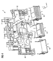
- FIG. 4 shows the installation of the roof module 2 in a vehicle body 9 according to the present invention.
- the assembly robot 20 sets the roof module 2 in the roof opening 10th (Hidden) of the vehicle body 9 fit with the outside 3 up one.
- FIGS. 1 to 4 also show a second assembly robot 30 with robot arm 32 and gripping device 33, which is identical to the mounting robot 20 and which the same Executes movement sequences. Furthermore, an adhesive application device 50 with adhesive application nozzle 51, which is identical to adhesive application device 40 and associated Adhesive application nozzle 41, shown.
- the vehicle body 9 by means of the Anlagenkarosserie makeupsystems 8 to a precise defined position. Then positioned the Assembly robot 20, 30 the roof module 2 precisely to the vehicle body 9, it adds to the final mounting position in the Vehicle body 9 and presses the roof module 2 at.
Landscapes
- Engineering & Computer Science (AREA)
- Manufacturing & Machinery (AREA)
- Chemical & Material Sciences (AREA)
- Combustion & Propulsion (AREA)
- Transportation (AREA)
- Mechanical Engineering (AREA)
- Automobile Manufacture Line, Endless Track Vehicle, Trailer (AREA)
- Automatic Assembly (AREA)
- Lens Barrels (AREA)
- Motor Or Generator Frames (AREA)
- Arrangement Or Mounting Of Propulsion Units For Vehicles (AREA)
Abstract
Description
- Figur 1
- zeigt schematisch eine erfindungsgemäße Montagezelle in Draufsicht,
- Figur 2
- zeigt die Aufnahme eines Dachmoduls durch einen Montageroboter gemäß der vorliegenden Erfindung,
- Figur 3
- zeigt den Kleberauftrag auf das Dachmodul gemäß der vorliegenden Erfindung und
- Figur 4
- zeigt den Einbau des Dachmöduls in eine Fahrzeugkarosserie gemäß der vorliegenden Erfindung.
- 1)
- Montagezelle
- 2)
- Dachmodul
- 3)
- Außenseite des Dachmoduls
- 4)
- Innenseite des Dachmoduls
- 5)
- Ladungsträger
- 6)
- Klebstofffass
- 7)
- Klebstoffpumpe
- 8)
- Fahrzeugkarosseriefördersystem
- 9)
- Fahrzeugkarosserie
- 10)
- Dachausschnitt
- 20)
- Montageroboter
- 21)
- Grundplatte
- 22)
- Roboterarm
- 23)
- Greifvorrichtung
- 30)
- Montageroboter
- 31)
- Grundplatte
- 32)
- Schwenkarm
- 33)
- Greifvorrichtung
- 40)
- Kleberapplikationenseinrichtung
- 41)
- Kleberapplikationsdüse
- 50)
- Kleberapplikationenseinrichtung
- 51)
- Kleberapplikationsdüse
- 60)
- neuer Ladungsträger mit neuen Dachmodulen
- 61)
- gemeinsame Entnahmestation für beide Roboter
- 62)
- leerer Ladungsträger nach Entnahme aller Dachmodule
Claims (7)
- Montagezelle (1) zum Ankleben eines Fahrzeugkarosserieteils (2) an eine Fahrzeugkarosserie (9), umfassend einen Montageroboter (20) mit einem Roboterarm (23) zur Aufnahme und Handhabung des Fahrzeugkarosserieteils (2),
wobei der Roboter (20) nach Aufnahme des Fahrzeugkarosserieteils (2) eingerichtet ist zur Durchführung der nachfolgenden Verfahrensschritte:Bewegen des Fahrzeugkarosserieteils (2) zu und entlang einer Kleberapplikationseinrichtung (40) zum Auftragen von wenigstens einer Klebestelle auf dem Fahrzeugkarosserieteil (2);Bewegen des mit Klebers versehenen Fahrzeugkarosserieteils (2) zur Fahrzeugkarosserie (9) undAndrücken der wenigstens einen Klebestelle an die Fahrzeugkarosserie (9) zum Ankleben des Fahrzeugkarosserieteils (2). - Verfahren zum Einkleben eines Fahrzeugkarosserieteils (2) in eine Fahrzeugkarosserie (9), welches die folgenden Schritte aufweist:Bereitstellen und Aufnehmen des Fahrzeugteils (2);Bewegen des umgedrehten Fahrzeugkarosserieteils (2) zu einer Kleberapplikationseinrichtung (40), welche eine Kleberapplikationsdüse (41) aufweist;Bewegen des umgedrehten Fahrzeugkarosserieteils (2) entlang einer vorgegebenen Bahn an einer Kleberapplikationsdüse (41), so dass Kleber auf dem Fahrzeugkarosserieteil (2) an wenigstens einer Klebestelle aufgetragen wird;Ausrichten des Fahrzeugkarosserieteils (2) passgenau zur Fahrzeugkarosserie (9);Bewegen des Fahrzeugkarosserieteils (2) in die Einbaulage und Andrücken der wenigstens einen Klebestelle des Fahrzeugkarosserieteils (2) an die Fahrzeugkarosserie (9);Loslassen des Fahrzeugkarosserieteils (2).
- Verfahren zum Einkleben eines Fahrzeugkarosserieteils (2) in eine Fahrzeugkarosserie (9) nach Anspruch 2,
wobei zum Kleberauftrag das Fahrzeugkarosserieteils (2) so gedreht wird, dass der Kleber auf eine oben gelegene Stelle des das Fahrzeugkarosserieteils (2) aufgebracht wird. - Montagezelle (1) zum Einkleben eines Fahrzeugkarosserieteils (2) in einen Ausschnitt (10) einer mittels eines Fahrzeugkarosseriefördersystems (8) zugeführten Fahrzeugkarosserie (9), welches die folgenden Komponenten aufweist:wobei der einzige Montageroboter (20) die vorstehenden, für das Einkleben des Fahrzeugkarosserieteils (2) benötigten Bewegungen durchführt.einen einzigen Montageroboter (20), welcher sich in alle drei Raumrichtungen bewegen kann;eine feststehende Kleberapplikationseinrichtung (40), mit einer Kleberdüse (41), wobei die Kleberdüse (41) genau eine Drehachse aufweist;
- Montagezelle (1) nach Anspruch 4,
mit einem zweiten Montageroboter (30) und mit einer zweiten Kleberapplikationseinrichtung (50),
wobei der zweite Montageroboter (30) identisch mit dem ersten Montageroboter (20) und die zweite Kleberapplikationseinrichtung (50) identisch mit der ersten Kleberapplikationseinrichtung (40) ist und
wobei der Montageroboter (20) und der Montageroboter (30) die vorstehenden, für das Einkleben des Fahrzeugkarosserieteils (2) benötigten Bewegungen alternierend durchführen. - Montagezelle (1) nach Anspruch 4 oder Anspruch 5,
dadurch gekennzeichnet, dass
der Montageroboter (20, 30) einen Roboterarm (22, 32) aufweist, mittels dessen das Fahrzeugkarosserieteil (2) im Raum schwenkbar ist. - Montagezelle (1) nach einem der Ansprüche 4 bis 6, welche Klebstofffässer (6) mit Klebstoffpumpen (7) aufweist.
Applications Claiming Priority (2)
| Application Number | Priority Date | Filing Date | Title |
|---|---|---|---|
| DE102004022382A DE102004022382A1 (de) | 2004-05-06 | 2004-05-06 | Montagesystem zum Einkleben eines Kraftfahrzeug-Karosserieteils in eine Fahrzeugkarosserie |
| DE102004022382 | 2004-05-06 |
Publications (3)
| Publication Number | Publication Date |
|---|---|
| EP1593589A2 true EP1593589A2 (de) | 2005-11-09 |
| EP1593589A3 EP1593589A3 (de) | 2006-05-24 |
| EP1593589B1 EP1593589B1 (de) | 2008-06-25 |
Family
ID=34936064
Family Applications (1)
| Application Number | Title | Priority Date | Filing Date |
|---|---|---|---|
| EP05009646A Expired - Lifetime EP1593589B1 (de) | 2004-05-06 | 2005-05-03 | Montagesystem zum Einkleben eines Kraftfahrzeug-Karosserieteils in eine Fahrzeugkarosserie |
Country Status (4)
| Country | Link |
|---|---|
| EP (1) | EP1593589B1 (de) |
| AT (1) | ATE399119T1 (de) |
| DE (2) | DE102004022382A1 (de) |
| ES (1) | ES2307089T3 (de) |
Cited By (2)
| Publication number | Priority date | Publication date | Assignee | Title |
|---|---|---|---|---|
| CN109630520A (zh) * | 2019-01-22 | 2019-04-16 | 浙江鑫沃特汽车工业有限公司 | 汽车扰流板打胶粘接自动线 |
| CZ310413B6 (cs) * | 2023-11-10 | 2025-05-28 | ŠKODA AUTO a.s. | Přípravek pro montáž skleněné střechy vozidla |
Families Citing this family (1)
| Publication number | Priority date | Publication date | Assignee | Title |
|---|---|---|---|---|
| US12420879B1 (en) * | 2024-05-29 | 2025-09-23 | Tesla, Inc. | Automated exterior vehicle part assembly using global datum |
Citations (1)
| Publication number | Priority date | Publication date | Assignee | Title |
|---|---|---|---|---|
| EP1291271A2 (de) | 2001-09-05 | 2003-03-12 | DaimlerChrysler AG | Montagesystem zum Einbau eines Dachmoduls in eine Fahrzeugkarosserie |
Family Cites Families (2)
| Publication number | Priority date | Publication date | Assignee | Title |
|---|---|---|---|---|
| US5845387A (en) * | 1995-09-25 | 1998-12-08 | Ford Global Technologies, Inc. | Automotive multi-panel compartment and method for making same |
| GB2312876B (en) * | 1996-04-24 | 2000-12-06 | Rover Group | A method of assembling a motor vehicle |
-
2004
- 2004-05-06 DE DE102004022382A patent/DE102004022382A1/de not_active Withdrawn
-
2005
- 2005-05-03 EP EP05009646A patent/EP1593589B1/de not_active Expired - Lifetime
- 2005-05-03 DE DE502005004494T patent/DE502005004494D1/de not_active Expired - Lifetime
- 2005-05-03 AT AT05009646T patent/ATE399119T1/de not_active IP Right Cessation
- 2005-05-03 ES ES05009646T patent/ES2307089T3/es not_active Expired - Lifetime
Patent Citations (1)
| Publication number | Priority date | Publication date | Assignee | Title |
|---|---|---|---|---|
| EP1291271A2 (de) | 2001-09-05 | 2003-03-12 | DaimlerChrysler AG | Montagesystem zum Einbau eines Dachmoduls in eine Fahrzeugkarosserie |
Cited By (2)
| Publication number | Priority date | Publication date | Assignee | Title |
|---|---|---|---|---|
| CN109630520A (zh) * | 2019-01-22 | 2019-04-16 | 浙江鑫沃特汽车工业有限公司 | 汽车扰流板打胶粘接自动线 |
| CZ310413B6 (cs) * | 2023-11-10 | 2025-05-28 | ŠKODA AUTO a.s. | Přípravek pro montáž skleněné střechy vozidla |
Also Published As
| Publication number | Publication date |
|---|---|
| EP1593589B1 (de) | 2008-06-25 |
| DE502005004494D1 (de) | 2008-08-07 |
| ES2307089T3 (es) | 2008-11-16 |
| ATE399119T1 (de) | 2008-07-15 |
| DE102004022382A1 (de) | 2005-12-01 |
| EP1593589A3 (de) | 2006-05-24 |
Similar Documents
| Publication | Publication Date | Title |
|---|---|---|
| EP1291271B1 (de) | Montagesystem zum Einbau eines Dachmoduls in eine Fahrzeugkarosserie | |
| DE69835380T2 (de) | Mehrfarben-spritzlackiersystem für kleine mengen | |
| DE3223264C2 (de) | Vorrichtung zum automatischen Montieren von Teilen | |
| EP2137053B1 (de) | Verfahren und vorrichtung zum befördern beweglicher werkzeuge | |
| DE3935992C2 (de) | Vorrichtung zum Verbinden zweier Glastafeln zu einer am Rand verklebten Isolierglasscheibe | |
| DE102005033972A1 (de) | Beschichtungsverfahren und zugehörige Beschichtungseinrichtung | |
| DE3222657A1 (de) | Einrichtung und verfahren zum automatischen montieren von teilen auf chassis | |
| EP1890929B1 (de) | Verfahren zum zusammenbauen von bauteilen einer fahrzeugkarosserie | |
| DE10302103A1 (de) | Montageeinrichtung für elektronische Bauteile und Montagekopfeinheit für elektronische Bauteile | |
| WO2017202961A1 (de) | Fertigungsstation und fertigungsverfahren | |
| DE10020231A1 (de) | Verfahren zur Kantenbearbeitung und Kantenbearbeitungssystem | |
| WO2014124835A1 (de) | Transportvorrichtung für eine fahrzeugmontageeinrichtung | |
| DE102014101722B4 (de) | Vorrichtung und Verfahren zum Erzeugen von Gebinden aus miteinander verklebten Behältern | |
| DE60121941T2 (de) | Herstellungsverfahren und herstellungsanlage | |
| EP1388614A2 (de) | Verfahren und Anordnung zur Aufnahme und zum Transport von Pfosten eines Leitplankensystems | |
| EP1593589B1 (de) | Montagesystem zum Einkleben eines Kraftfahrzeug-Karosserieteils in eine Fahrzeugkarosserie | |
| EP1792812A2 (de) | Bearbeitungsstation und Verfahren zur Fertigung von Karosserien | |
| WO2009000513A1 (de) | Fügestation für karosseriebauteile | |
| DE102006020922B4 (de) | Vorrichtung zum Bearbeiten von Bauteilen einer Kraftfahrzeugkarosserie | |
| WO2006021264A1 (de) | Vorrichtung zum beschichten, insbesondere zum lackieren, von gegenständen, insbesondere von fahrzeugkarosserien | |
| WO2009065788A1 (de) | Anlage zur herstellung einer leichtbaustruktur | |
| DE3831392C2 (de) | ||
| DE102014201706A1 (de) | Vorrichtung und Verfahren zum Applizieren einer Folie auf ein Fahrzeugteil | |
| DE10253817A1 (de) | Verfahren und Vorrichtung zum Schweissen von Bauteilen einer Karosserie | |
| DE4326318A1 (de) | Verfahren, Magazinier- und Reinigungs-Einrichtung und Großplotter zum automatischen Säubern und Einrüsten von Paletten mit Querabstellern |
Legal Events
| Date | Code | Title | Description |
|---|---|---|---|
| PUAI | Public reference made under article 153(3) epc to a published international application that has entered the european phase |
Free format text: ORIGINAL CODE: 0009012 |
|
| AK | Designated contracting states |
Kind code of ref document: A2 Designated state(s): AT BE BG CH CY CZ DE DK EE ES FI FR GB GR HU IE IS IT LI LT LU MC NL PL PT RO SE SI SK TR |
|
| AX | Request for extension of the european patent |
Extension state: AL BA HR LV MK YU |
|
| PUAL | Search report despatched |
Free format text: ORIGINAL CODE: 0009013 |
|
| AK | Designated contracting states |
Kind code of ref document: A3 Designated state(s): AT BE BG CH CY CZ DE DK EE ES FI FR GB GR HU IE IS IT LI LT LU MC NL PL PT RO SE SI SK TR |
|
| AX | Request for extension of the european patent |
Extension state: AL BA HR LV MK YU |
|
| 17P | Request for examination filed |
Effective date: 20061110 |
|
| AKX | Designation fees paid |
Designated state(s): AT BE BG CH CY CZ DE DK EE ES FI FR GB GR HU IE IS IT LI LT LU MC NL PL PT RO SE SI SK TR |
|
| 17Q | First examination report despatched |
Effective date: 20070525 |
|
| GRAP | Despatch of communication of intention to grant a patent |
Free format text: ORIGINAL CODE: EPIDOSNIGR1 |
|
| GRAS | Grant fee paid |
Free format text: ORIGINAL CODE: EPIDOSNIGR3 |
|
| GRAA | (expected) grant |
Free format text: ORIGINAL CODE: 0009210 |
|
| AK | Designated contracting states |
Kind code of ref document: B1 Designated state(s): AT BE BG CH CY CZ DE DK EE ES FI FR GB GR HU IE IS IT LI LT LU MC NL PL PT RO SE SI SK TR |
|
| REG | Reference to a national code |
Ref country code: GB Ref legal event code: FG4D Free format text: NOT ENGLISH |
|
| REG | Reference to a national code |
Ref country code: CH Ref legal event code: EP |
|
| REF | Corresponds to: |
Ref document number: 502005004494 Country of ref document: DE Date of ref document: 20080807 Kind code of ref document: P |
|
| REG | Reference to a national code |
Ref country code: IE Ref legal event code: FG4D Free format text: LANGUAGE OF EP DOCUMENT: GERMAN |
|
| PG25 | Lapsed in a contracting state [announced via postgrant information from national office to epo] |
Ref country code: FI Free format text: LAPSE BECAUSE OF FAILURE TO SUBMIT A TRANSLATION OF THE DESCRIPTION OR TO PAY THE FEE WITHIN THE PRESCRIBED TIME-LIMIT Effective date: 20080625 Ref country code: SI Free format text: LAPSE BECAUSE OF FAILURE TO SUBMIT A TRANSLATION OF THE DESCRIPTION OR TO PAY THE FEE WITHIN THE PRESCRIBED TIME-LIMIT Effective date: 20080625 |
|
| REG | Reference to a national code |
Ref country code: ES Ref legal event code: FG2A Ref document number: 2307089 Country of ref document: ES Kind code of ref document: T3 |
|
| PG25 | Lapsed in a contracting state [announced via postgrant information from national office to epo] |
Ref country code: PL Free format text: LAPSE BECAUSE OF FAILURE TO SUBMIT A TRANSLATION OF THE DESCRIPTION OR TO PAY THE FEE WITHIN THE PRESCRIBED TIME-LIMIT Effective date: 20080625 Ref country code: NL Free format text: LAPSE BECAUSE OF FAILURE TO SUBMIT A TRANSLATION OF THE DESCRIPTION OR TO PAY THE FEE WITHIN THE PRESCRIBED TIME-LIMIT Effective date: 20080625 |
|
| NLV1 | Nl: lapsed or annulled due to failure to fulfill the requirements of art. 29p and 29m of the patents act | ||
| PG25 | Lapsed in a contracting state [announced via postgrant information from national office to epo] |
Ref country code: CZ Free format text: LAPSE BECAUSE OF FAILURE TO SUBMIT A TRANSLATION OF THE DESCRIPTION OR TO PAY THE FEE WITHIN THE PRESCRIBED TIME-LIMIT Effective date: 20080625 Ref country code: IS Free format text: LAPSE BECAUSE OF FAILURE TO SUBMIT A TRANSLATION OF THE DESCRIPTION OR TO PAY THE FEE WITHIN THE PRESCRIBED TIME-LIMIT Effective date: 20081025 Ref country code: SE Free format text: LAPSE BECAUSE OF FAILURE TO SUBMIT A TRANSLATION OF THE DESCRIPTION OR TO PAY THE FEE WITHIN THE PRESCRIBED TIME-LIMIT Effective date: 20080925 Ref country code: LT Free format text: LAPSE BECAUSE OF FAILURE TO SUBMIT A TRANSLATION OF THE DESCRIPTION OR TO PAY THE FEE WITHIN THE PRESCRIBED TIME-LIMIT Effective date: 20080625 Ref country code: PT Free format text: LAPSE BECAUSE OF FAILURE TO SUBMIT A TRANSLATION OF THE DESCRIPTION OR TO PAY THE FEE WITHIN THE PRESCRIBED TIME-LIMIT Effective date: 20081125 |
|
| REG | Reference to a national code |
Ref country code: IE Ref legal event code: FD4D |
|
| PG25 | Lapsed in a contracting state [announced via postgrant information from national office to epo] |
Ref country code: SK Free format text: LAPSE BECAUSE OF FAILURE TO SUBMIT A TRANSLATION OF THE DESCRIPTION OR TO PAY THE FEE WITHIN THE PRESCRIBED TIME-LIMIT Effective date: 20080625 Ref country code: RO Free format text: LAPSE BECAUSE OF FAILURE TO SUBMIT A TRANSLATION OF THE DESCRIPTION OR TO PAY THE FEE WITHIN THE PRESCRIBED TIME-LIMIT Effective date: 20080625 |
|
| REG | Reference to a national code |
Ref country code: GB Ref legal event code: 732E Free format text: REGISTERED BETWEEN 20090305 AND 20090311 |
|
| PG25 | Lapsed in a contracting state [announced via postgrant information from national office to epo] |
Ref country code: IE Free format text: LAPSE BECAUSE OF FAILURE TO SUBMIT A TRANSLATION OF THE DESCRIPTION OR TO PAY THE FEE WITHIN THE PRESCRIBED TIME-LIMIT Effective date: 20080625 Ref country code: EE Free format text: LAPSE BECAUSE OF FAILURE TO SUBMIT A TRANSLATION OF THE DESCRIPTION OR TO PAY THE FEE WITHIN THE PRESCRIBED TIME-LIMIT Effective date: 20080625 Ref country code: BG Free format text: LAPSE BECAUSE OF FAILURE TO SUBMIT A TRANSLATION OF THE DESCRIPTION OR TO PAY THE FEE WITHIN THE PRESCRIBED TIME-LIMIT Effective date: 20080925 Ref country code: DK Free format text: LAPSE BECAUSE OF FAILURE TO SUBMIT A TRANSLATION OF THE DESCRIPTION OR TO PAY THE FEE WITHIN THE PRESCRIBED TIME-LIMIT Effective date: 20080625 |
|
| PLBE | No opposition filed within time limit |
Free format text: ORIGINAL CODE: 0009261 |
|
| STAA | Information on the status of an ep patent application or granted ep patent |
Free format text: STATUS: NO OPPOSITION FILED WITHIN TIME LIMIT |
|
| 26N | No opposition filed |
Effective date: 20090326 |
|
| PG25 | Lapsed in a contracting state [announced via postgrant information from national office to epo] |
Ref country code: IT Free format text: LAPSE BECAUSE OF FAILURE TO SUBMIT A TRANSLATION OF THE DESCRIPTION OR TO PAY THE FEE WITHIN THE PRESCRIBED TIME-LIMIT Effective date: 20080625 |
|
| REG | Reference to a national code |
Ref country code: GB Ref legal event code: 732E Free format text: REGISTERED BETWEEN 20091029 AND 20091104 |
|
| BERE | Be: lapsed |
Owner name: GM GLOBAL TECHNOLOGY OPERATIONS, INC. Effective date: 20090531 |
|
| REG | Reference to a national code |
Ref country code: GB Ref legal event code: 732E Free format text: REGISTERED BETWEEN 20091105 AND 20091111 |
|
| PG25 | Lapsed in a contracting state [announced via postgrant information from national office to epo] |
Ref country code: MC Free format text: LAPSE BECAUSE OF NON-PAYMENT OF DUE FEES Effective date: 20090531 |
|
| REG | Reference to a national code |
Ref country code: CH Ref legal event code: PL |
|
| PG25 | Lapsed in a contracting state [announced via postgrant information from national office to epo] |
Ref country code: CH Free format text: LAPSE BECAUSE OF NON-PAYMENT OF DUE FEES Effective date: 20090531 Ref country code: LI Free format text: LAPSE BECAUSE OF NON-PAYMENT OF DUE FEES Effective date: 20090531 |
|
| PG25 | Lapsed in a contracting state [announced via postgrant information from national office to epo] |
Ref country code: BE Free format text: LAPSE BECAUSE OF NON-PAYMENT OF DUE FEES Effective date: 20090531 |
|
| REG | Reference to a national code |
Ref country code: ES Ref legal event code: FD2A Effective date: 20090504 |
|
| PG25 | Lapsed in a contracting state [announced via postgrant information from national office to epo] |
Ref country code: AT Free format text: LAPSE BECAUSE OF NON-PAYMENT OF DUE FEES Effective date: 20090503 |
|
| PG25 | Lapsed in a contracting state [announced via postgrant information from national office to epo] |
Ref country code: GR Free format text: LAPSE BECAUSE OF FAILURE TO SUBMIT A TRANSLATION OF THE DESCRIPTION OR TO PAY THE FEE WITHIN THE PRESCRIBED TIME-LIMIT Effective date: 20080926 Ref country code: ES Free format text: LAPSE BECAUSE OF NON-PAYMENT OF DUE FEES Effective date: 20090504 |
|
| PG25 | Lapsed in a contracting state [announced via postgrant information from national office to epo] |
Ref country code: LU Free format text: LAPSE BECAUSE OF NON-PAYMENT OF DUE FEES Effective date: 20090503 |
|
| REG | Reference to a national code |
Ref country code: DE Ref legal event code: R081 Ref document number: 502005004494 Country of ref document: DE Owner name: GM GLOBAL TECHNOLOGY OPERATIONS LLC (N. D. GES, US Free format text: FORMER OWNER: GM GLOBAL TECHNOLOGY OPERATIONS, INC., DETROIT, MICH., US Effective date: 20110323 Ref country code: DE Ref legal event code: R081 Ref document number: 502005004494 Country of ref document: DE Owner name: GM GLOBAL TECHNOLOGY OPERATIONS LLC (N. D. GES, US Free format text: FORMER OWNER: GM GLOBAL TECHNOLOGY OPERATIONS, INC., DETROIT, US Effective date: 20110323 |
|
| PG25 | Lapsed in a contracting state [announced via postgrant information from national office to epo] |
Ref country code: HU Free format text: LAPSE BECAUSE OF FAILURE TO SUBMIT A TRANSLATION OF THE DESCRIPTION OR TO PAY THE FEE WITHIN THE PRESCRIBED TIME-LIMIT Effective date: 20081226 |
|
| PG25 | Lapsed in a contracting state [announced via postgrant information from national office to epo] |
Ref country code: TR Free format text: LAPSE BECAUSE OF FAILURE TO SUBMIT A TRANSLATION OF THE DESCRIPTION OR TO PAY THE FEE WITHIN THE PRESCRIBED TIME-LIMIT Effective date: 20080625 |
|
| PG25 | Lapsed in a contracting state [announced via postgrant information from national office to epo] |
Ref country code: CY Free format text: LAPSE BECAUSE OF FAILURE TO SUBMIT A TRANSLATION OF THE DESCRIPTION OR TO PAY THE FEE WITHIN THE PRESCRIBED TIME-LIMIT Effective date: 20080625 |
|
| REG | Reference to a national code |
Ref country code: FR Ref legal event code: PLFP Year of fee payment: 12 |
|
| PGFP | Annual fee paid to national office [announced via postgrant information from national office to epo] |
Ref country code: DE Payment date: 20160426 Year of fee payment: 12 Ref country code: GB Payment date: 20160427 Year of fee payment: 12 |
|
| PGFP | Annual fee paid to national office [announced via postgrant information from national office to epo] |
Ref country code: FR Payment date: 20160412 Year of fee payment: 12 |
|
| REG | Reference to a national code |
Ref country code: DE Ref legal event code: R119 Ref document number: 502005004494 Country of ref document: DE |
|
| GBPC | Gb: european patent ceased through non-payment of renewal fee |
Effective date: 20170503 |
|
| REG | Reference to a national code |
Ref country code: FR Ref legal event code: ST Effective date: 20180131 |
|
| PG25 | Lapsed in a contracting state [announced via postgrant information from national office to epo] |
Ref country code: GB Free format text: LAPSE BECAUSE OF NON-PAYMENT OF DUE FEES Effective date: 20170503 Ref country code: DE Free format text: LAPSE BECAUSE OF NON-PAYMENT OF DUE FEES Effective date: 20171201 |
|
| PG25 | Lapsed in a contracting state [announced via postgrant information from national office to epo] |
Ref country code: FR Free format text: LAPSE BECAUSE OF NON-PAYMENT OF DUE FEES Effective date: 20170531 |