EP1593571A1 - Klotzbremseinrichtung eines Drehgestells eines Schienenfahrzeugs mit sphärisch gelagerten Hängelaschen - Google Patents
Klotzbremseinrichtung eines Drehgestells eines Schienenfahrzeugs mit sphärisch gelagerten Hängelaschen Download PDFInfo
- Publication number
- EP1593571A1 EP1593571A1 EP05016869A EP05016869A EP1593571A1 EP 1593571 A1 EP1593571 A1 EP 1593571A1 EP 05016869 A EP05016869 A EP 05016869A EP 05016869 A EP05016869 A EP 05016869A EP 1593571 A1 EP1593571 A1 EP 1593571A1
- Authority
- EP
- European Patent Office
- Prior art keywords
- brake
- bogie
- block
- wheels
- pads
- Prior art date
- Legal status (The legal status is an assumption and is not a legal conclusion. Google has not performed a legal analysis and makes no representation as to the accuracy of the status listed.)
- Granted
Links
Images





Classifications
-
- B—PERFORMING OPERATIONS; TRANSPORTING
- B61—RAILWAYS
- B61H—BRAKES OR OTHER RETARDING DEVICES SPECIALLY ADAPTED FOR RAIL VEHICLES; ARRANGEMENT OR DISPOSITION THEREOF IN RAIL VEHICLES
- B61H13/00—Actuating rail-vehicle brakes
- B61H13/34—Details
- B61H13/36—Beams; Suspension thereof
-
- B—PERFORMING OPERATIONS; TRANSPORTING
- B60—VEHICLES IN GENERAL
- B60T—VEHICLE BRAKE CONTROL SYSTEMS OR PARTS THEREOF; BRAKE CONTROL SYSTEMS OR PARTS THEREOF, IN GENERAL; ARRANGEMENT OF BRAKING ELEMENTS ON VEHICLES IN GENERAL; PORTABLE DEVICES FOR PREVENTING UNWANTED MOVEMENT OF VEHICLES; VEHICLE MODIFICATIONS TO FACILITATE COOLING OF BRAKES
- B60T13/00—Transmitting braking action from initiating means to ultimate brake actuator with power assistance or drive; Brake systems incorporating such transmitting means, e.g. air-pressure brake systems
- B60T13/10—Transmitting braking action from initiating means to ultimate brake actuator with power assistance or drive; Brake systems incorporating such transmitting means, e.g. air-pressure brake systems with fluid assistance, drive, or release
- B60T13/24—Transmitting braking action from initiating means to ultimate brake actuator with power assistance or drive; Brake systems incorporating such transmitting means, e.g. air-pressure brake systems with fluid assistance, drive, or release the fluid being gaseous
- B60T13/26—Compressed-air systems
- B60T13/36—Compressed-air systems direct, i.e. brakes applied directly by compressed air
- B60T13/365—Compressed-air systems direct, i.e. brakes applied directly by compressed air for railway vehicles
-
- B—PERFORMING OPERATIONS; TRANSPORTING
- B61—RAILWAYS
- B61H—BRAKES OR OTHER RETARDING DEVICES SPECIALLY ADAPTED FOR RAIL VEHICLES; ARRANGEMENT OR DISPOSITION THEREOF IN RAIL VEHICLES
- B61H13/00—Actuating rail-vehicle brakes
- B61H13/20—Transmitting mechanisms
- B61H13/24—Transmitting mechanisms for cars with two axles or bogies with two axles and braking cylinder(s) for each bogie, the mechanisms at each side being interconnected
Definitions
- the invention relates to a block brake device of a bogie of a rail vehicle including two sets of wheels with two wheels, as well as two each a wheel axle associated and parallel to this vedaufende brake beam, which Wear brake pads and communicate with each other via push rods the by at least one pressure-medium-actuated cylinder piston drive for braking engagement the brake pads are operable with associated braking surfaces of the wheels, wherein a brake module comprising at least the brake beams, the push rods, the brake pads and the cylinder piston drive by hanging tabs on the bogie is attached hanging, according to the preamble of claim 1.
- Such a block brake device is known, for example, from WO 00/02756, wherein the brake beams are formed by plate profiles.
- the as U or Z profile trained plate profile of a brake beam carries two pressure-actuated cylinder piston drives as separate, independent building units, each one Press push rod.
- the central axes of the cylinder piston drives extend along the transom. Consequently, the extension movement of the pistons takes place in parallel the wheel axles instead of and must by diversion gear on the transverse to the wheel axles arranged push rods are deflected, which in case of braking the Move the crossbeams away from each other and press the brake pads against the wheels.
- the Brake bars are hinged by means of hanging plates on the bogie, which a Have rotational freedom about pivot axes which are parallel to the wheel axles.
- the present invention is based on the object, a block brake device of the type mentioned in such a way that they have a ensures better braking effect.
- the hangers are inclined at transverse movements of the wheel axles, whereby the brake beams can also follow transverse movements of the wheel axles, which For example, come from a resilient mounting of the chassis.
- This kinematics ge technicallydeistet that on the radially projecting wheel flanges of the wheels laterally pending and still held vertically brakes in the wheel plane and remain aligned substantially parallel to the wheel brake surface.
- an inclination of the brake pads relative to the Wheel braking surfaces avoided, resulting in a reduction of the effective braking surface and thus would result in a reduction in braking performance.
- the brake pads are bearing brake shoes on the brake beam about parallel to the wheel axles extending pivot axes hinged pivotally.
- the brake shoes are tilted and can Position optimally on the wheel brake surfaces during braking.
- the swiveling Storage can be realized by brake shoe bolt, which on the one hand by Through holes in fork-shaped, each end to the brake beam arranged, the brake shoes encompassing recordings and by a central through hole of the brake shoe are inserted.
- the hanging tabs on the brake pads bearing brake shoes are pivotally mounted on all sides. This creates a very compact storage.
- the spherical bearings include elastic-damping Elements
- the bogie-side spherical bearings are preferably in the form of Spheroidal blocks present, with a ball head of a ball stud within a Rubber sleeve is mounted with complementary spherical bearing surface.
- the the ball head enclosing rubber sleeve caused by a restoring moment as a result of her Elasticity that the block brake device at the transition from the Zuspannwolf in the release position returns to the starting position, in which the brake pads are almost equidistant from the associated braking surfaces of the wheels are removed.
- the block brake device 1 is a block brake device 1 of a freight car according to a preferred Embodiment of the invention shown.
- the block brake device 1 is in the whole attached to a bogie 2 of the freight wagon shown in Figure 11 hanging, which has two sets of wheels 4, each with two wheels 6.
- the block brake device 1 preferably comprises two by push rods 8 related to each other Brake bar 10, 12, four on the brake beams 10, 12 end-held and Brake pads 14 carrying brake shoes 16, four on the one hand to the brake beam 10, 12 and on the other hand hinged on the bogie 2 hanging tabs 18 and for example two accommodated in the brake beam 10 designed as a hollow housing, in Fig.1 not visible brake actuators 20a, 20b.
- the brake pads 14 a Brake bar 10, 12 are associated with the wheels 6 a wheel axle 22, wherein the brake beams 10, 12 extend approximately parallel to the wheel axles 22.
- the two Wheelsets 4 are resiliently mounted relative to the bogie 2 in a known manner. The suspension allows that the two wheelsets 4 among other longitudinal and Can perform transverse movements relative to the bogie 2.
- the push rods 8 are actuated such that the brake beams 10, 12th moved away from each other and thereby the pads worn by them 14th be brought against the wheels 6 in Bremszuspann too.
- the push rods 8 are substantially perpendicular to the brake beams 10, 12 are arranged.
- the hanging tabs 18 are preferably pivotally mounted on the bogie 2 on all sides.
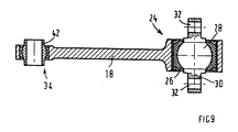
- a spherical block 24 is used as a pivot bearing, i.e. a within a rubber sleeve 26 with complementary spherical bearing surface mounted ball head 28 of a ball stud 30, as shown in the sectional view through a single hanging tab 18 as shown in Fig.9 shows.
- the ball stud 30 is preferably designed as a flat bolt with two through holes 32 at the ends, wherein the flat bolt 30 preferably on a longitudinal beam, not shown of the bogie 2 is added.
- the all-round pivoting storage of Hanging tabs 18 allows, on the one hand, that the brake beams 10, 12 together with the brake pads 14 the transverse movements of the wheelsets 4 in the direction of the axles 22 can be followed to ensure that they are always the braking surfaces of the Wheels 6 are opposite.
- the spherical block 24 allows pivoting the hanging tabs 18 in the longitudinal or direction of travel. Such Pivoting movement takes place, for example, when the brake actuators 20a, 20b be actuated and thus the wheel-side ends 34 of the hanging tabs 18 across to the wheel axles 22 away from each other or to each other. Furthermore Such a possibility of rotation for the hanging tabs 18 must be given in order to To be able to compensate for the wear occurring on the brake pads 14.
- the hanging tabs 18 must be in at least two rotational degrees of freedom with respect be pivoted to the bogie 2, which by any kind of spherical bearing or by a sufficiently large game of storage of the hanging tabs 18 am Bogie is feasible.
- the rubber head 26 enclosing the ball head 28 causes by a restoring moment due to their elasticity, that the pad brake device 1 at the transition from the Zuspannwolf in the release position to the starting position € Victoria, in which the brake pads 14 almost equidistant from the associated braking surfaces of the wheels 6 are removed.
- the pads 14 are supporting Brake shoes 16 to the brake beams 10, 12 to parallel to the wheel axles 22nd extending pivot axes pivotally hinged.
- This is the brake shoes 16 tiltable and can be optimal in braking to the braking surfaces the wheels 6 create.
- the pivot bearing is for example by Bremsschuhbolzen 36 realized which through forked through holes in forked trained, each end to the brake beam 10, 12 arranged, the Brake shoes 16 enclosing receptacles 38 and through a central through hole the respective brake shoe 16 are inserted.
- This kinematics allows an inclination of the hanging tabs 18 in transverse movements of the wheel axles 22, while at the radially projecting Flanges 44 of the wheels 6 laterally pending and through the brake shoe bolt still held vertically brake shoes 16 in the wheel plane substantially stay aligned parallel to the wheel brake surface.
- a brake beam 10 In the formed as a hollow housing a brake beam 10 are two coaxial and counteracting cylinder piston drives 20a, 20b integrated. Make up at least portions of the brake beam 10 itself, the cylinder 46 of the cylinder piston engine 20a, 20b, as is apparent in particular from FIG. More precisely, the Cylinder surfaces 48 of the cylinder 46 of the cylinder piston drives 20a, 20b preferably directly through an inner peripheral surface of the wall 50 of the hollow Brake bar 10 formed. Alternatively, the cylinder surfaces 48 also by formed by the wall 50 of the brake beam 10 cylinder liners become. As best seen in Fig.11, this has the one brake beam 10th Representing housing two with respect to a median plane of the bogie.
- housing halves 52 Symmetrical umtschbar and identically formed housing halves 52 as a hollow Moldings, of which each housing half 52 sections a cylinder 46 of a cylinder piston engine 20a, 20b forms.
- These housing halves 52 are in 3 individually shown, wherein the opposite in the mounted state Sections 54 of the housing halves 52 each have a cylindrical cross section, to form on the inner circumferential surface of the cylinder surface 48. the End of the cylindrical portion 54, a flange 56 is also formed.
- the cylindrical one Section 54 closes outwardly a section 58 with substantially rectangular cross-section and with a transverse to a central axis 62nd the cylinder piston drives 20a, 20b extending bag-like formation 60, in which ever a deflection gear 64 for deflecting the along the central axes 62nd the cylinder piston drives 20a, 20b piston movements on the perpendicular is added to these arranged push rods 8.
- the from the flanges 56 facing away ends of the housing halves 52 are already mentioned, forked Shooting 38 formed for the brake shoes 16.
- a clam shell intermediate housing 66 in which a central, visible in the sectional plane of Fig.6a and each a pressure chamber 68 of the cylinder 46 with pressure medium supplying pressure medium connection 70 is formed.
- the intermediate housing 66 is between the housing halves 52, for example by means of the flanges 56 engaging tie rods 72nd held, which passed through through holes of the intermediate housing 66 are.
- the other, executed without Bremsaktuator brake beam 12 is conventional formed, for example as a double U-profile and is also end with provided fork-shaped receptacles 38 for brake shoes 16, as Fig.1 shows.
- FIG 2 only one housing half 52 is shown for reasons of scale, however Both housing halves are identical with the housed in them assemblies built up.
- the pistons 74a, 74b of the cylinder piston gears 20a, 20b point to yours Pressure side depending on a central cup-shaped molding 76, from which head side a central, coaxial with the central axis 62 piston rod 78 protrudes outward.
- the pistons 74a, 74b are by themselves held in the housing halves 52 shelves 80 supporting return springs 82 biased in release position.
- the Piston rod 78 is attached to a longer leg 84 of a two-legged angle lever Hinged 86, for example, the deflection gear 64 forms.
- the angle lever 64 is of the bag-like formation 60 of the corresponding housing half 52 completely enclosed and in relation to this by means of a pin bearing 88 pivotally mounted.
- the two legs 84, 90 of the angle lever 86 are approximately perpendicular to each other, wherein the shorter leg 90 at one end of the associated Push rod 8 is articulated, which consists of a transverse to the central axis 62 of the cylinder piston engine 20a, 20b disposed opening 92 of the housing half 52 protrudes.
- a different gear ratio can be achieved, for example 4/1 or 3/1.
- a parking brake which is a by Feststellbremsbetuschistorsorgane rotatably driven and with the cylinder piston drives 20a, 20b coaxial nut spindle drive 102, wherein the spindle 104 on the pressure side of the piston 74a of the one cylinder piston engine 20a and the nut 106 on the Pressure side of the piston 74 b of the other cylinder piston engine 20 b can be stopped is trained.
- handwheels For applying and releasing the parking brake, for example arranged on the side surface of the rail vehicle, for reasons of scale not shown handwheels a rotary motion in preferably two parallel to the wheel axles 22 extending propeller shafts 108 introduced, which of both Side forth in a projecting extension 110 of the intermediate housing 66 open and there with each an input shaft 112, 114 of a gear transmission 116 in rotary connection which are best seen in the sectional drawing according to Fig.6b is.
- the parking brake in practice from only one side of the rail vehicle is operated, carry the two input shafts 112, 114 meshing with each other Gears 118, so that a rotational connection between the two propeller shafts 108th consists.
- the parking brake is turned by a clockwise rotation of the handwheels tightened and released by turning to the left.
- To forward the rotary motion on the nut-spindle drive 102 are the input shafts 112, 114, for example, two Subordinate gear stages 120, wherein the output of the gear transmission 116 via a central gear 122 takes place, which with a coaxial, in the intermediate housing 66 preferably mounted by roller bearings 124, cylindrical sleeve 126 in one piece is formed ( Figure 4).
- the central gear 122 could also be on the sleeve 126 shrunk.
- the ends of the sleeve 126 and the two bottoms 128 of the Intermediate housing is ever a movement seal 130 interposed to the axially adjacent on both sides pressure chambers 68 of the cylinder piston drives 20a, 20b seal against the interior of the intermediate housing 66.
- sleeve 126 encloses nut 106 of the nut spindle drive 102 and is rotatably connected to this.
- the mother is 106 received axially displaceable within the sleeve 126.
- This can be, for example be realized by a coupling between the sleeve 126 and the nut 106 is effected by a spline 132 or a feather key. Consequently, the entire Nut spindle drive 102 relative to the sleeve 126 in the direction of the central axis 62 of the Cylinder piston drives 20a, 20b mounted axially displaceable or floating.
- the spindle 104 and nut 106 of the nut spindle drive 102 are within the cup-shaped formations 76 of the associated pistons 74a, 74b linearly displaceable guided, as can be seen from the sectional view of Figure 5.
- the spindle 104 associated stop body 134a is rotatably connected thereto during the mother 106 associated stop body 134b is connected to a stub shaft 140 which is opposite to a coupled with the nut 106 sleeve-shaped end piece 144, for example by means an axial needle bearing 148 is rotatable.
- the spindle 104 of the nut spindle drive 102 is screwed within the nut 106 by a thread 150, so that an over the gear transmission 116 introduced rotation of the sleeve 126 screwing the Spindle 104 causes relative to the nut 106, whereby the mother-spin drive 102nd lengthens or shortens.
- this stop body 134a, 134b another function as a driver for the pistons 74a, 74b in Case of parking brake off.
- Fig.7 shows the situation in which the service brake by pressurization the pressure chambers 68 of the cylinder piston drives 20a, 20b applied, the parking brake but still solved. Accordingly, move at a service brake the two pistons 74a, 74b are similar to the action of the return springs 82 as in a boxer arrangement outward away from each other and press on the Piston rods 78 and the angle lever 86, the push rods 8, whereby the two Brake bar 10, 12 away from each other and the brake pads 14 against the braking surfaces the wheels 6 are pressed.
- the parking brake is in Zuspann too, because due to an introduced into the gear transmission 116 rotational movement the sleeve 126 is rotated and thereby in relation to its stop body 134b by means of the axial needle bearing 148 freely rotatable nut 106 relative to the was screwed by its stopper body 134a twist-secured spindle 104.
- the nut-spindle drive 102 has lengthened on both sides, wherein the Longitudinal force on the stopper body 134a, 134b transmitted to the piston 74a, 74b and the latter then against the action of the remindsteilfedem 82 outward urged and the brake pads 14 as already described in the service braking brought into braking engagement position.
- the situation of Figure 8 can also be characterized be caused that first the service brake and then additionally the parking brake is applied.
- Fig.11 and Fig.12 are the same and the same as in the previous example Parts are marked by the same reference lines.
- first embodiment is in the embodiment of Fig.10 no parking brake and therefore no corresponding drive mechanism available, so that in the intermediate housing 66, only the common pressure medium connection 70 together Feed channels is present.
- the intermediate housing 66 is in both cases preferably identical to the number of identical parts of different brake variants to increase.
- the push rods 8 are perpendicular to the brake beams 10, 12 arranged push rods 8 below a cross member of the bogie guided.
- the push rods 8 are arranged at an angle to each other and diverge preferably starting from the one brake beam 10 in which the cylinder piston drives 20a, 20b are included.
- the push rods 8 at a central, drawn down portion of a cross member 154 of the bogie pass right and left.
- the Push rods 8 also be guided through through holes in the cross member 154. In the latter case, it is necessary that for assembly and disassembly of the block brake device 1, the push rods 8 of the brake actuators 20a, 20b easily separable are.
- an additional balancing device 156 present in order to release the block brake device 1 a one-sided Contact the brake pads 14 with the wheels to avoid 6 or the same size Anlegewege the brake pads 14 to achieve.
- a telescope device 158 provided with within a cylinder 160 linearly guided rod 162, wherein by means of a friction element 164 between rod 162 and cylinder 160 a frictional connection is generated, which counteracts a change in length of the telescope device 158.
- the telescopic device 158 is preferably parallel to the vehicle longitudinal direction arranged, the rod 162, for example, on the bogie 2 and the cylinder 160 at the shorter leg 90 of the angle lever 86 centrally between the Pin bearing 88 and its linkage 98 on the push rod 8 at a pivot point 166 is articulated, which is indicated by the identical measures "a".
- the Function of the balancing device 156 is then as follows: During a service brake the push rod 8 is actuated by a total path, which differs from the Sum of the application path of the brake pads 14 of a brake beam 10 to the associated wheels 6 and the Anlegeweges the brake pads 14 of the other Brake bar 12 composed of the associated wheels 6. At the same size Mooring paths, i.
Landscapes
- Engineering & Computer Science (AREA)
- Mechanical Engineering (AREA)
- Transportation (AREA)
- Braking Arrangements (AREA)
Abstract
Description
- Fig.1
- eine perspektivische Darstellung einer Klotzbremseinrichtung gemäß einer ersten Ausführungsform der Erfindung mit einem Bremsbalken in Form eines Gehäuses, das gleichzeitig die Zylinder von Zylinder-Kolbentrieben bildet;
- Fig.2
- eine Schnittdarstellung durch einen Teil des Gehäuses mit einem Zylinder-Kolbentrieb der Klotzbremseinrichtung;
- Fig.3
- Gehäusehälften des Gehäuses von Fig.1;
- Fig.4
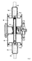
- eine vergrößerte Schnittdarstellung der Zylinder-Kolbentriebe;
- Fig.5
- eine Schnittdarstellung entlang der Linie V-V von Fig.4;
- Fig.6a
- eine Schnittdarstellung entlang der Linie Vla von Fig.4;
- Fig.6b
- eine Schnittdarstellung entlang der Linie Vlb von Fig.4;
- Fig.7
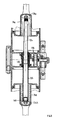
- die Zylinder-Kolbentriebe von Fig.4 bei gelöster Feststellbremse und bei zugespannter Betriebsbremse;
- Fig.8
- die Zylinder-Kolbentriebe von Fig.4 bei zugespannter Feststellbremse;
- Fig.9
- eine Schnittdarstellung einer einzelnen Hängelasche;
- Fig.10
- eine vergrößerte Schnittdarstellung einer Klotzbremseinrichtung gemäß einer weiteren Ausführungsform;
- Fig.11
- eine Ansicht von unten auf ein Drehgestell mit einer Klotzbremseinrichtung gemäß einer weiteren Ausführungsform;
- Fig.12
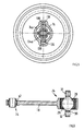
- eine Vorderansicht des Drehgestells von Fig.11;
- Fig.13
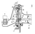
- einen Teilschnitt einer weiteren Ausführungsform einer Klotzbremseinrichtung.
- 1
- Klotzbremseinrichtung
- 2
- Drehgestell
- 4
- Radsätze
- 6
- Räder
- 8
- Druckstangen
- 10
- Bremsbalken
- 12
- Bremsbalken
- 14
- Bremsklötze
- 16
- Bremsschuhe
- 18
- Hängelaschen
- 20a,b
- Zylinder-Kolbentriebe
- 22
- Radachsen
- 24
- Sphäroblock
- 26
- Gummihülle
- 28
- Kugelkopf
- 30
- Kugelbolzen
- 32
- Durchgangsbohrungen
- 34
- Ende
- 36
- Bremsschuhbolzen
- 38
- Aufnahmen
- 40
- Lager
- 42
- Hülse
- 44
- Spurkränze
- 46
- Zylinder
- 48
- Zylinderlauffläche
- 50
- Wandung
- 52
- Gehäusehälften
- 54
- zyl. Abschnitt
- 56
- Flansch
- 58
- Abschnitt
- 60
- Ausformung
- 62
- Mittelachse
- 64
- Umlenkungsgetriebe
- 66
- Zwischengehäuse
- 68
- Druckraum
- 70
- Druckmittelanschluß
- 72
- Zuganker
- 74a,b
- Kolben
- 76
- Ausformung
- 78
- Kolbenstange
- 80
- Zwischenboden
- 82
- Rücksteilfedem
- 84
- Schenkel
- 86
- Winkelhebel
- 88
- Bolzenlagerung
- 90
- Schenkel
- 92
- Öffnung
- 94
- Dichtung
- 96
- Montageöffnung
- 98
- Anlenkung
- 100
- Antriebsmechanik
- 102
- Mutter-Spindeltrieb
- 104
- Spindel
- 106
- Mutter
- 108
- Gelenkwellen
- 110
- Fortsatz
- 112
- Eingangswelle
- 114
- Eingangswelle
- 116
- Zahnradgetriebe
- 118
- Zahnräder
- 120
- Zahnradstufen
- 122
- zentrales Zahnrad
- 124
- Wälzlager
- 126
- Hülse
- 128
- Boden
- 130
- Bewegungsdichtung
- 132
- Keilwellenprofil
- 134a,b
- Anschlagkörper
- 136
- Seitenflügel
- 138
- Nuten
- 140
- Wellenstumpf
- 144
- Endstück
- 148
- Axialnadellager
- 150
- Gewinde
- 152
- Boden
- 154
- Querträger
- 156
- Symmetrieeinrichtung
- 158
- Teleskopeinrichtung
- 160
- Zylinder
- 162
- Stab
- 164
- Reibelement
- 166
- Anlenkpunkt
Claims (6)
- Klotzbremseinrichtung (1) eines Drehgestells (2) eines Schienenfahrzeugs beinhaltend zwei Radsätze (4) mit je zwei Rädern (6), sowie zwei jeweils einer Radachse (22) zugeordnete und parallel zu dieser vedaufende Bremsbalken (10, 12), welche Bremsklötze (14) tragen und über Druckstangen (8) miteinander in Verbindung stehen, die durch wenigstens einen druckmittelbetätigten Zylinder-Kolbentrieb (20a, 20b) zum Bremseingriff der Bremsklötze (14) mit zugeordneten Bremsflächen der Räder (6) betätigbar sind, wobei ein Bremsmodul beinhaltend wenigstens die Bremsbalken (10, 12), die Druckstangen (8), die Bremsklötze (14) und den Zylinder-Kolbentrieb (20a, 20b) durch Hängelaschen (18) am Drehgestell (2) hängend befestigt ist, dadurch gekennzeichnet, dass die Hängelaschen (18) durch jeweils sphärische Lager (24, 40) einendseitig am Drehgestell (2) und anderendseitig an den Bremsbalken (10, 12) allseitig schwenkbar gelagert sind.
- Klotzbremseinrichtung nach Anspruch 1, dadurch gekennzeichnet, dass die Bremsklötze (14) tragende Bremsschuhe (16) an den Bremsbalken (10, 12) um parallel zu den Radachsen (22) verlaufende Schwenkachsen schwenkbar angelenkt sind.
- Klotzbremseinrichtung nach Anspruch 2, dadurch gekennzeichnet, dass die schwenkbare Lagerung durch Bremsschuhbolzen (36) realisiert ist, welche durch Durchgangsbohrungen in gabelförmig ausgebildeten, je endseitig an den Bremsbalken (10, 12) angeordneten, die Bremsschuhe (16) umgreifenden Aufnahmen (38) sowie durch eine zentrale Durchgangsbohrung des Bremsschuhs (16) gesteckt sind.
- Klotzbremseinrichtung nach wenigsten seinem der vorhergehenden Ansprüche, dadurch gekennzeichnet, dass die Hängelaschen (18) an den die Bremsklötze (14) tragenden Bremsschuhen (16) allseitig schwenkbar gelagert sind.
- Klotzbremseinrichtung nach wenigstens einem der vorhergehenden Ansprüche, dadurch gekennzeichnet, dass die sphärischen Lager (24) elastisch-dämpfende Elemente (26) beinhalten.
- Klotzbremseinrichtung nach Anspruch 5, dadurch gekennzeichnet, dass die drehgestellseitigen sphärischen Lager (24) Sphäroblöcke beinhalten, wobei ein Kugelkopf (28) eines Kugelbolzens (30) innerhalb einer Gummihülle (26) mit komplementärer sphärischer Lagerfläche gelagert ist.
Applications Claiming Priority (3)
| Application Number | Priority Date | Filing Date | Title |
|---|---|---|---|
| DE10304716A DE10304716B4 (de) | 2003-02-06 | 2003-02-06 | Klotzbremseinrichtung eines Drehgestells eines Schienenfahrzeugs |
| DE10304716 | 2003-02-06 | ||
| EP04002399A EP1457402B1 (de) | 2003-02-06 | 2004-02-04 | Klotzbremseinrichtung eines Drehgestells eines Schienenfahrzeugs |
Related Parent Applications (1)
| Application Number | Title | Priority Date | Filing Date |
|---|---|---|---|
| EP04002399A Division EP1457402B1 (de) | 2003-02-06 | 2004-02-04 | Klotzbremseinrichtung eines Drehgestells eines Schienenfahrzeugs |
Publications (2)
| Publication Number | Publication Date |
|---|---|
| EP1593571A1 true EP1593571A1 (de) | 2005-11-09 |
| EP1593571B1 EP1593571B1 (de) | 2008-04-30 |
Family
ID=32730788
Family Applications (2)
| Application Number | Title | Priority Date | Filing Date |
|---|---|---|---|
| EP04002399A Expired - Lifetime EP1457402B1 (de) | 2003-02-06 | 2004-02-04 | Klotzbremseinrichtung eines Drehgestells eines Schienenfahrzeugs |
| EP05016869A Expired - Lifetime EP1593571B1 (de) | 2003-02-06 | 2004-02-04 | Klotzbremseinrichtung eines Drehgestells eines Schienenfahrzeugs mit sphärisch gelagerten Hängelaschen |
Family Applications Before (1)
| Application Number | Title | Priority Date | Filing Date |
|---|---|---|---|
| EP04002399A Expired - Lifetime EP1457402B1 (de) | 2003-02-06 | 2004-02-04 | Klotzbremseinrichtung eines Drehgestells eines Schienenfahrzeugs |
Country Status (6)
| Country | Link |
|---|---|
| US (1) | US7165659B2 (de) |
| EP (2) | EP1457402B1 (de) |
| JP (1) | JP4773056B2 (de) |
| AT (2) | ATE393725T1 (de) |
| DE (3) | DE10304716B4 (de) |
| ES (2) | ES2303917T3 (de) |
Cited By (1)
| Publication number | Priority date | Publication date | Assignee | Title |
|---|---|---|---|---|
| CZ306673B6 (cs) * | 2012-12-05 | 2017-05-03 | Dako-Cz A.S. | Trámcová brzda kolejových vozidel |
Families Citing this family (10)
| Publication number | Priority date | Publication date | Assignee | Title |
|---|---|---|---|---|
| RU2288124C1 (ru) * | 2005-05-19 | 2006-11-27 | Открытое акционерное общество "Крюковский вагоностроительный завод" (ОАО "КВСЗ") | Триангель тормоза тележки грузового вагона |
| DE102005045879B3 (de) * | 2005-06-23 | 2007-01-04 | Knorr-Bremse Systeme für Schienenfahrzeuge GmbH | Handbremsvorrichtung eines Schienenfahrzeugs mit innerhalb des Handrades angeordnetem Anzeigeelement |
| DE102008045711A1 (de) * | 2008-09-04 | 2010-03-18 | Knorr-Bremse Systeme für Schienenfahrzeuge GmbH | Pneumatische Bremseinrichtung |
| SE535759C2 (sv) * | 2011-04-06 | 2012-12-11 | Faiveley Transport Nordic Ab | Bromsaktuator för ett rälsfordon med en bromsblockhållare |
| CN104470784B (zh) * | 2011-12-27 | 2018-06-01 | 西屋公司 | 集成转向架制动器及用于该集成转向架制动器的调整臂 |
| CN104875768B (zh) * | 2015-05-28 | 2017-08-11 | 南车二七车辆有限公司 | 一种采用紧凑式制动夹钳单元的铁路车辆转向架制动吊座 |
| PL70929Y1 (pl) * | 2017-08-29 | 2019-08-30 | Univ Technologiczno Przyrodniczy Im Jana I Jedrzeja Sniadeckich W Bydgoszczy | Mechaniczny hamulec klockowy pojazdu szynowego |
| CN111907497B (zh) * | 2020-08-14 | 2022-11-18 | 中车齐齐哈尔车辆有限公司 | 一种集成制动装置及具有其的铁路货车 |
| EP4585475A1 (de) | 2024-01-12 | 2025-07-16 | Siemens Mobility GmbH | Bremsvorrichtung mit abstandssensor zum einsatz bei einer zwillingsachse eines spurgeführten fahrzeugs, abstandssensor und verfahren zum betreiben einer bremsvorrichtung |
| DE102024118792A1 (de) * | 2024-07-02 | 2026-01-08 | Knorr-Bremse Systeme für Schienenfahrzeuge GmbH | Klotzbremseinrichtung für eine an einem Drehgestell eines Schienenfahrzeugs angeordnete Klotzbremseinrichtung sowie Klotzbremseinrichtung |
Citations (3)
| Publication number | Priority date | Publication date | Assignee | Title |
|---|---|---|---|---|
| WO2000002756A1 (en) | 1998-07-13 | 2000-01-20 | Sab Wabco Ab | A bogie brake |
| WO2001036247A1 (en) * | 1999-11-18 | 2001-05-25 | Sab Wabco Ab | A block holder for a bogie brake |
| WO2002074601A1 (en) * | 2001-03-20 | 2002-09-26 | Sab Wabco Ab | A bogie brake |
Family Cites Families (12)
| Publication number | Priority date | Publication date | Assignee | Title |
|---|---|---|---|---|
| US2958398A (en) * | 1957-09-05 | 1960-11-01 | Westinghouse Air Brake Co | Brake rigging for railway cars |
| US3017959A (en) * | 1959-04-29 | 1962-01-23 | Westinghouse Air Brake Co | Foundation brake apparatus |
| US3088550A (en) * | 1961-05-12 | 1963-05-07 | Westinghouse Air Brake Co | Brake beam with integrally formed brake cylinder |
| JPS4319049Y1 (de) * | 1965-01-14 | 1968-08-08 | ||
| JPS538408B2 (de) * | 1972-11-13 | 1978-03-28 | ||
| US4134343A (en) * | 1976-09-27 | 1979-01-16 | General Steel Industries, Inc. | Radial axle railway truck |
| ZA866098B (en) * | 1985-09-16 | 1987-03-25 | Gen Signal Corp | Rail car brake apparatus |
| IT1241010B (it) | 1990-11-15 | 1993-12-27 | Wabco Westinghouse Compagnia Freni S.P.A. | Attuatore pneumatico doppio con recupero automatico dei giochi per freni di veicoli ferroviari |
| US5507368A (en) * | 1995-04-10 | 1996-04-16 | Ellcon National, Inc. | Railway car truck mounted brake assembly with multiple piston air cylinder |
| US5667040A (en) * | 1995-12-12 | 1997-09-16 | New York Air Brake Corporation | Method for changing a packing cup on a brake actuation-slack adjuster |
| US5785159A (en) | 1996-06-05 | 1998-07-28 | Triax-Davis, Inc. | Braking mechanism for railroad cars having both pneumatic and mechanical actuators |
| US5817375A (en) * | 1997-04-07 | 1998-10-06 | E.J.P. Machine, Inc. | Process for improving the performance and extending the life of railroad car brake assembly components |
-
2003
- 2003-02-06 DE DE10304716A patent/DE10304716B4/de not_active Expired - Fee Related
-
2004
- 2004-02-04 AT AT05016869T patent/ATE393725T1/de active
- 2004-02-04 US US10/770,400 patent/US7165659B2/en not_active Expired - Lifetime
- 2004-02-04 EP EP04002399A patent/EP1457402B1/de not_active Expired - Lifetime
- 2004-02-04 AT AT04002399T patent/ATE393074T1/de active
- 2004-02-04 DE DE502004006999T patent/DE502004006999D1/de not_active Expired - Lifetime
- 2004-02-04 ES ES04002399T patent/ES2303917T3/es not_active Expired - Lifetime
- 2004-02-04 ES ES05016869T patent/ES2303977T3/es not_active Expired - Lifetime
- 2004-02-04 EP EP05016869A patent/EP1593571B1/de not_active Expired - Lifetime
- 2004-02-04 JP JP2004028587A patent/JP4773056B2/ja not_active Expired - Fee Related
- 2004-02-04 DE DE502004006878T patent/DE502004006878D1/de not_active Expired - Lifetime
Patent Citations (3)
| Publication number | Priority date | Publication date | Assignee | Title |
|---|---|---|---|---|
| WO2000002756A1 (en) | 1998-07-13 | 2000-01-20 | Sab Wabco Ab | A bogie brake |
| WO2001036247A1 (en) * | 1999-11-18 | 2001-05-25 | Sab Wabco Ab | A block holder for a bogie brake |
| WO2002074601A1 (en) * | 2001-03-20 | 2002-09-26 | Sab Wabco Ab | A bogie brake |
Cited By (1)
| Publication number | Priority date | Publication date | Assignee | Title |
|---|---|---|---|---|
| CZ306673B6 (cs) * | 2012-12-05 | 2017-05-03 | Dako-Cz A.S. | Trámcová brzda kolejových vozidel |
Also Published As
| Publication number | Publication date |
|---|---|
| EP1457402B1 (de) | 2008-04-23 |
| ES2303977T3 (es) | 2008-09-01 |
| US20040200679A1 (en) | 2004-10-14 |
| ES2303917T3 (es) | 2008-09-01 |
| DE10304716B4 (de) | 2006-12-21 |
| US7165659B2 (en) | 2007-01-23 |
| EP1593571B1 (de) | 2008-04-30 |
| DE502004006999D1 (de) | 2008-06-12 |
| JP2004237977A (ja) | 2004-08-26 |
| JP4773056B2 (ja) | 2011-09-14 |
| ATE393074T1 (de) | 2008-05-15 |
| EP1457402A1 (de) | 2004-09-15 |
| DE502004006878D1 (de) | 2008-06-05 |
| DE10304716A1 (de) | 2004-08-19 |
| ATE393725T1 (de) | 2008-05-15 |
Similar Documents
| Publication | Publication Date | Title |
|---|---|---|
| EP0777598B1 (de) | Bremszangeneinheit für scheibenbremsen von fahrzeugen, insbesondere schienenfahrzeugen | |
| EP1457401B1 (de) | Bremsvorrichtung eines Schienenfahrzeugs | |
| DE102009013005B3 (de) | Doppelkolben-Scheibenbremse | |
| DE3031862C2 (de) | Gelenkfahrzeug mit mehreren Achsen | |
| EP1593571B1 (de) | Klotzbremseinrichtung eines Drehgestells eines Schienenfahrzeugs mit sphärisch gelagerten Hängelaschen | |
| DE1605307A1 (de) | Bremsenmontage fuer das rollende Material von Eisenbahnen | |
| EP0732247B1 (de) | Scheibenbremse für Schienenfahrzeuge | |
| DE2234410C3 (de) | Querkupplungssystem für Schienenfahrzeuge mit mehrachsigen Drehgestellen | |
| EP0562598A1 (de) | Gelenkverbindung zwischen zwei gelenkig miteinander verbundenen Fahrzeugen | |
| EP0046457B1 (de) | Vierachsiges Drehgestell für Niederflurwagen | |
| DE102015210917A1 (de) | Gelenkverbindung und Anordnung zur Aufhängung eines Rades | |
| EP0306888B1 (de) | Lenkbare Vorderachse für Kraftfahrzeuge | |
| DE2261843B2 (de) | Selbsttaetige, doppeltwirkende bremsgestaengenachstelleinrichtung im bremsgestaenge, insbesondere von schienenfahrzeugen | |
| DE4210828A1 (de) | Bremszange fuer eine elektrohydraulisch betaetigbare zangenscheibenbremse, insbesondere fuer strassenbahnwagen | |
| DE2055364C3 (de) | Schaltgetriebe für die Lenkung von Fahrzeugrädern, insbesondere von Kraftfahrzeugen mit Mehrachslenkung | |
| DE202009016346U1 (de) | Hinterachslenkvorrichtung für drehschemelgelenkte Anhängefahrzeuge, insbesondere für Schneidwerkswagen | |
| EP2343229B1 (de) | Lenkachse | |
| EP2871114B1 (de) | Lenkachse | |
| EP1452418A1 (de) | Eisenbahngüterwageneinheit | |
| DE2237449B1 (de) | ||
| DE10304717A1 (de) | Klotzbremseinrichtung für Radsätze eines Drehgestells eines Schienenfahrzeugs | |
| EP0930210A1 (de) | Fahrwerk für Schienenfahrzeuge und Schienenfahrzeug mit mindestens einem derartigen Fahrwerk | |
| EP1915282B1 (de) | Fahrzeug mit wankstützen | |
| DE60304717T2 (de) | Verbesserte Hebelschnittstelle in einem Handbremssystem für eine einzylindrige am Waggon montierte Eisenbahnbremse | |
| AT403791B (de) | Klotzbremse mit rad- und zusatzbremsklötzen für schienenfahrzeuge |
Legal Events
| Date | Code | Title | Description |
|---|---|---|---|
| PUAI | Public reference made under article 153(3) epc to a published international application that has entered the european phase |
Free format text: ORIGINAL CODE: 0009012 |
|
| AC | Divisional application: reference to earlier application |
Ref document number: 1457402 Country of ref document: EP Kind code of ref document: P |
|
| AK | Designated contracting states |
Kind code of ref document: A1 Designated state(s): AT BE BG CH CY CZ DE DK EE ES FI FR GB GR HU IE IT LI LU MC NL PT RO SE SI SK TR |
|
| 17P | Request for examination filed |
Effective date: 20060509 |
|
| AKX | Designation fees paid |
Designated state(s): AT BE BG CH CY CZ DE DK EE ES FI FR GB GR HU IE IT LI LU MC NL PT RO SE SI SK TR |
|
| 17Q | First examination report despatched |
Effective date: 20060628 |
|
| GRAP | Despatch of communication of intention to grant a patent |
Free format text: ORIGINAL CODE: EPIDOSNIGR1 |
|
| GRAS | Grant fee paid |
Free format text: ORIGINAL CODE: EPIDOSNIGR3 |
|
| GRAA | (expected) grant |
Free format text: ORIGINAL CODE: 0009210 |
|
| AC | Divisional application: reference to earlier application |
Ref document number: 1457402 Country of ref document: EP Kind code of ref document: P |
|
| AK | Designated contracting states |
Kind code of ref document: B1 Designated state(s): AT BE BG CH CY CZ DE DK EE ES FI FR GB GR HU IE IT LI LU MC NL PT RO SE SI SK TR |
|
| REG | Reference to a national code |
Ref country code: GB Ref legal event code: FG4D Free format text: NOT ENGLISH |
|
| REG | Reference to a national code |
Ref country code: CH Ref legal event code: EP |
|
| REG | Reference to a national code |
Ref country code: IE Ref legal event code: FG4D Free format text: LANGUAGE OF EP DOCUMENT: GERMAN |
|
| REF | Corresponds to: |
Ref document number: 502004006999 Country of ref document: DE Date of ref document: 20080612 Kind code of ref document: P |
|
| REG | Reference to a national code |
Ref country code: SE Ref legal event code: TRGR |
|
| REG | Reference to a national code |
Ref country code: ES Ref legal event code: FG2A Ref document number: 2303977 Country of ref document: ES Kind code of ref document: T3 |
|
| PG25 | Lapsed in a contracting state [announced via postgrant information from national office to epo] |
Ref country code: SI Free format text: LAPSE BECAUSE OF FAILURE TO SUBMIT A TRANSLATION OF THE DESCRIPTION OR TO PAY THE FEE WITHIN THE PRESCRIBED TIME-LIMIT Effective date: 20080430 |
|
| NLV1 | Nl: lapsed or annulled due to failure to fulfill the requirements of art. 29p and 29m of the patents act | ||
| PG25 | Lapsed in a contracting state [announced via postgrant information from national office to epo] |
Ref country code: NL Free format text: LAPSE BECAUSE OF FAILURE TO SUBMIT A TRANSLATION OF THE DESCRIPTION OR TO PAY THE FEE WITHIN THE PRESCRIBED TIME-LIMIT Effective date: 20080430 Ref country code: BG Free format text: LAPSE BECAUSE OF FAILURE TO SUBMIT A TRANSLATION OF THE DESCRIPTION OR TO PAY THE FEE WITHIN THE PRESCRIBED TIME-LIMIT Effective date: 20080730 Ref country code: FI Free format text: LAPSE BECAUSE OF FAILURE TO SUBMIT A TRANSLATION OF THE DESCRIPTION OR TO PAY THE FEE WITHIN THE PRESCRIBED TIME-LIMIT Effective date: 20080430 Ref country code: PT Free format text: LAPSE BECAUSE OF FAILURE TO SUBMIT A TRANSLATION OF THE DESCRIPTION OR TO PAY THE FEE WITHIN THE PRESCRIBED TIME-LIMIT Effective date: 20080930 |
|
| REG | Reference to a national code |
Ref country code: IE Ref legal event code: FD4D |
|
| ET | Fr: translation filed | ||
| PG25 | Lapsed in a contracting state [announced via postgrant information from national office to epo] |
Ref country code: CZ Free format text: LAPSE BECAUSE OF FAILURE TO SUBMIT A TRANSLATION OF THE DESCRIPTION OR TO PAY THE FEE WITHIN THE PRESCRIBED TIME-LIMIT Effective date: 20080430 Ref country code: IE Free format text: LAPSE BECAUSE OF FAILURE TO SUBMIT A TRANSLATION OF THE DESCRIPTION OR TO PAY THE FEE WITHIN THE PRESCRIBED TIME-LIMIT Effective date: 20080430 Ref country code: DK Free format text: LAPSE BECAUSE OF FAILURE TO SUBMIT A TRANSLATION OF THE DESCRIPTION OR TO PAY THE FEE WITHIN THE PRESCRIBED TIME-LIMIT Effective date: 20080430 |
|
| PG25 | Lapsed in a contracting state [announced via postgrant information from national office to epo] |
Ref country code: RO Free format text: LAPSE BECAUSE OF FAILURE TO SUBMIT A TRANSLATION OF THE DESCRIPTION OR TO PAY THE FEE WITHIN THE PRESCRIBED TIME-LIMIT Effective date: 20080430 Ref country code: SK Free format text: LAPSE BECAUSE OF FAILURE TO SUBMIT A TRANSLATION OF THE DESCRIPTION OR TO PAY THE FEE WITHIN THE PRESCRIBED TIME-LIMIT Effective date: 20080430 |
|
| PLBE | No opposition filed within time limit |
Free format text: ORIGINAL CODE: 0009261 |
|
| STAA | Information on the status of an ep patent application or granted ep patent |
Free format text: STATUS: NO OPPOSITION FILED WITHIN TIME LIMIT |
|
| 26N | No opposition filed |
Effective date: 20090202 |
|
| PG25 | Lapsed in a contracting state [announced via postgrant information from national office to epo] |
Ref country code: EE Free format text: LAPSE BECAUSE OF FAILURE TO SUBMIT A TRANSLATION OF THE DESCRIPTION OR TO PAY THE FEE WITHIN THE PRESCRIBED TIME-LIMIT Effective date: 20080430 |
|
| BERE | Be: lapsed |
Owner name: KNORR-BREMSE SYSTEME FUR SCHIENENFAHRZEUGE G.M.B. Effective date: 20090228 |
|
| PG25 | Lapsed in a contracting state [announced via postgrant information from national office to epo] |
Ref country code: MC Free format text: LAPSE BECAUSE OF NON-PAYMENT OF DUE FEES Effective date: 20090228 |
|
| REG | Reference to a national code |
Ref country code: CH Ref legal event code: PL |
|
| PG25 | Lapsed in a contracting state [announced via postgrant information from national office to epo] |
Ref country code: CH Free format text: LAPSE BECAUSE OF NON-PAYMENT OF DUE FEES Effective date: 20090228 Ref country code: LI Free format text: LAPSE BECAUSE OF NON-PAYMENT OF DUE FEES Effective date: 20090228 |
|
| PG25 | Lapsed in a contracting state [announced via postgrant information from national office to epo] |
Ref country code: BE Free format text: LAPSE BECAUSE OF NON-PAYMENT OF DUE FEES Effective date: 20090228 |
|
| PG25 | Lapsed in a contracting state [announced via postgrant information from national office to epo] |
Ref country code: GR Free format text: LAPSE BECAUSE OF FAILURE TO SUBMIT A TRANSLATION OF THE DESCRIPTION OR TO PAY THE FEE WITHIN THE PRESCRIBED TIME-LIMIT Effective date: 20080731 |
|
| PG25 | Lapsed in a contracting state [announced via postgrant information from national office to epo] |
Ref country code: LU Free format text: LAPSE BECAUSE OF NON-PAYMENT OF DUE FEES Effective date: 20090204 |
|
| PG25 | Lapsed in a contracting state [announced via postgrant information from national office to epo] |
Ref country code: HU Free format text: LAPSE BECAUSE OF FAILURE TO SUBMIT A TRANSLATION OF THE DESCRIPTION OR TO PAY THE FEE WITHIN THE PRESCRIBED TIME-LIMIT Effective date: 20081101 |
|
| PG25 | Lapsed in a contracting state [announced via postgrant information from national office to epo] |
Ref country code: TR Free format text: LAPSE BECAUSE OF FAILURE TO SUBMIT A TRANSLATION OF THE DESCRIPTION OR TO PAY THE FEE WITHIN THE PRESCRIBED TIME-LIMIT Effective date: 20080430 |
|
| PG25 | Lapsed in a contracting state [announced via postgrant information from national office to epo] |
Ref country code: CY Free format text: LAPSE BECAUSE OF FAILURE TO SUBMIT A TRANSLATION OF THE DESCRIPTION OR TO PAY THE FEE WITHIN THE PRESCRIBED TIME-LIMIT Effective date: 20080430 |
|
| REG | Reference to a national code |
Ref country code: FR Ref legal event code: PLFP Year of fee payment: 13 |
|
| REG | Reference to a national code |
Ref country code: FR Ref legal event code: PLFP Year of fee payment: 14 |
|
| REG | Reference to a national code |
Ref country code: FR Ref legal event code: PLFP Year of fee payment: 15 |
|
| PGFP | Annual fee paid to national office [announced via postgrant information from national office to epo] |
Ref country code: GB Payment date: 20220221 Year of fee payment: 19 Ref country code: DE Payment date: 20220217 Year of fee payment: 19 Ref country code: AT Payment date: 20220215 Year of fee payment: 19 |
|
| PGFP | Annual fee paid to national office [announced via postgrant information from national office to epo] |
Ref country code: SE Payment date: 20220221 Year of fee payment: 19 Ref country code: IT Payment date: 20220228 Year of fee payment: 19 Ref country code: FR Payment date: 20220221 Year of fee payment: 19 Ref country code: ES Payment date: 20220318 Year of fee payment: 19 |
|
| P01 | Opt-out of the competence of the unified patent court (upc) registered |
Effective date: 20230508 |
|
| REG | Reference to a national code |
Ref country code: DE Ref legal event code: R119 Ref document number: 502004006999 Country of ref document: DE |
|
| REG | Reference to a national code |
Ref country code: SE Ref legal event code: EUG |
|
| REG | Reference to a national code |
Ref country code: AT Ref legal event code: MM01 Ref document number: 393725 Country of ref document: AT Kind code of ref document: T Effective date: 20230204 |
|
| GBPC | Gb: european patent ceased through non-payment of renewal fee |
Effective date: 20230204 |
|
| PG25 | Lapsed in a contracting state [announced via postgrant information from national office to epo] |
Ref country code: SE Free format text: LAPSE BECAUSE OF NON-PAYMENT OF DUE FEES Effective date: 20230205 Ref country code: AT Free format text: LAPSE BECAUSE OF NON-PAYMENT OF DUE FEES Effective date: 20230204 |
|
| PG25 | Lapsed in a contracting state [announced via postgrant information from national office to epo] |
Ref country code: GB Free format text: LAPSE BECAUSE OF NON-PAYMENT OF DUE FEES Effective date: 20230204 |
|
| PG25 | Lapsed in a contracting state [announced via postgrant information from national office to epo] |
Ref country code: IT Free format text: LAPSE BECAUSE OF NON-PAYMENT OF DUE FEES Effective date: 20230204 Ref country code: GB Free format text: LAPSE BECAUSE OF NON-PAYMENT OF DUE FEES Effective date: 20230204 Ref country code: FR Free format text: LAPSE BECAUSE OF NON-PAYMENT OF DUE FEES Effective date: 20230228 Ref country code: DE Free format text: LAPSE BECAUSE OF NON-PAYMENT OF DUE FEES Effective date: 20230901 |
|
| REG | Reference to a national code |
Ref country code: ES Ref legal event code: FD2A Effective date: 20240402 |
|
| PG25 | Lapsed in a contracting state [announced via postgrant information from national office to epo] |
Ref country code: ES Free format text: LAPSE BECAUSE OF NON-PAYMENT OF DUE FEES Effective date: 20230205 |
|
| PG25 | Lapsed in a contracting state [announced via postgrant information from national office to epo] |
Ref country code: ES Free format text: LAPSE BECAUSE OF NON-PAYMENT OF DUE FEES Effective date: 20230205 |