EP1593342A1 - Magnetic field-producing device - Google Patents
Magnetic field-producing device Download PDFInfo
- Publication number
- EP1593342A1 EP1593342A1 EP04709360A EP04709360A EP1593342A1 EP 1593342 A1 EP1593342 A1 EP 1593342A1 EP 04709360 A EP04709360 A EP 04709360A EP 04709360 A EP04709360 A EP 04709360A EP 1593342 A1 EP1593342 A1 EP 1593342A1
- Authority
- EP
- European Patent Office
- Prior art keywords
- magnetic field
- magnetic
- pair
- field generator
- magnetic poles
- Prior art date
- Legal status (The legal status is an assumption and is not a legal conclusion. Google has not performed a legal analysis and makes no representation as to the accuracy of the status listed.)
- Granted
Links
Images






Classifications
-
- G—PHYSICS
- G01—MEASURING; TESTING
- G01R—MEASURING ELECTRIC VARIABLES; MEASURING MAGNETIC VARIABLES
- G01R33/00—Arrangements or instruments for measuring magnetic variables
- G01R33/20—Arrangements or instruments for measuring magnetic variables involving magnetic resonance
- G01R33/28—Details of apparatus provided for in groups G01R33/44 - G01R33/64
- G01R33/38—Systems for generation, homogenisation or stabilisation of the main or gradient magnetic field
- G01R33/383—Systems for generation, homogenisation or stabilisation of the main or gradient magnetic field using permanent magnets
-
- H—ELECTRICITY
- H01—ELECTRIC ELEMENTS
- H01F—MAGNETS; INDUCTANCES; TRANSFORMERS; SELECTION OF MATERIALS FOR THEIR MAGNETIC PROPERTIES
- H01F7/00—Magnets
- H01F7/02—Permanent magnets [PM]
- H01F7/0273—Magnetic circuits with PM for magnetic field generation
- H01F7/0278—Magnetic circuits with PM for magnetic field generation for generating uniform fields, focusing, deflecting electrically charged particles
Definitions
- the present invention relates to a magnetic field generator, and more specifically to a permanent magnet type magnetic field generator used in an MRI (Magnetic Resonance Imaging) apparatus, an ESR imaging (Electron Spin Resonance Imaging) apparatus or an apparatus which serves as both.
- MRI Magnetic Resonance Imaging
- ESR imaging Electro Spin Resonance Imaging
- JP-A 9-299347 proposes an apparatus which generates a magnetic field for an MRI and a magnetic field for an ESR imaging, with a single electric magnet. According to this method, the amount of electric current is varied in a single electric magnet, to switch between a resonance magnetic field strength for ESR imaging and a resonance magnetic field strength for MRI.
- a permanent-magnet type magnetic field generator which has a plurality of magnetic field uniformity spaces.
- the magnetic field generator according to the present invention is a permanent magnet type. Therefore, unlike those which use electric magnets, there is no need for operations to switch electric currents.
- By adjusting the magnetic fields generated in the plurality of magnetic field uniformity spaces in advance a highly uniform magnetic field is obtained at a plurality of places in a single magnetic field generator, and it is possible to sustain the magnetic field uniformity and strength. Therefore, even when the magnetic field uniformity spaces generate different magnetic fields from each other, highly accurate magnetic field distribution is obtainable.
- an apparatus which serves as both high-quality MRI apparatus and ESR imaging apparatus and an MRI apparatus which allows simultaneous MRI image taking of two or more parts.
- the magnetic field generator includes: a pair of yokes faced to each other with a gap in between; and at least two pairs of magnetic poles.
- the poles in each pair are faced with each other between the pair of yokes, and the magnetic field uniformity space is formed between each pair of the magnetic poles.
- a plurality of pairs of magnetic poles are provided between a pair of yokes, and it is possible to form a plurality of magnetic field uniformity spaces between one pair of yokes. Therefore, magnetic efficiency can be improved over a case where a plurality of magnetic field generators are placed side by side, making possible to reduce the size of the apparatus.
- the magnetic pole includes a pole piece. In this case, it is possible to improve uniformity of the magnetic field uniformity space.
- At least part of one yoke in the pair of yokes is movable toward and away from the other yoke.
- strength and uniformity of the magnetic field generated in the magnetic field uniformity space are adjustable as necessary.
- At least a pair of the magnetic poles includes a permanent magnet group.
- a permanent magnet group it is possible to build a magnetic circuit which passes through such a pair of magnetic poles and the other pair of magnetic poles. Therefore, even if the other pair of magnetic poles does not include permanent magnet groups, it is possible to form a magnetic field uniformity space between that pair of magnetic poles. Further, it becomes possible to reduce a total amount of permanent magnet used for the construction, and thereby to reduce the weight of magnetic field generator.
- two magnetic field uniformity spaces which are adjacent to each other have different magnetic field strengths from each other as necessary. This enables to obtain a magnetic field generator suitable for an apparatus which serves as both MRI apparatus and ESR imaging apparatus for example.
- two magnetic field uniformity spaces which are adjacent to each other have their magnetic field directions differing from each other by 180 degrees.
- two pairs of magnetic poles are provided between the pair of yokes:
- One of the pairs of magnetic poles includes a permanent magnet group provided by rare-earth magnets whereas the other pair of magnetic poles includes a permanent magnet group provided by ferrite magnets.
- two pairs of magnetic poles are provided between the pair of yokes.
- one of the pairs of magnetic poles includes a permanent magnet group provided by rare-earth magnets whereas the other pair of magnetic poles includes a padding member and a permanent magnet group provided by rare-earth magnets which are disposed on a main surface of the padding member.
- a padding member as described, it becomes possible to differentiate magnetic field strengths in the two magnetic fields generated by respective pairs of magnetic poles, while keeping respective gap dimensions in the two pairs of magnetic poles identical with each other, even if both pairs of magnetic poles include permanent magnet groups which are made of rare-earth magnets. Therefore, in this case again, a magnetic field generator suitable for an apparatus which serves as both MRI apparatus and ESR imaging apparatus is obtained.
- electromagnetic shielding means is provided between two magnetic field uniformity spaces which are adjacent to each other. This eliminates interference by noises due to signal generation etc. in each of the magnetic field uniformity spaces, and improves the quality of obtained image. Further, it becomes possible to reduce the distance between mutually adjacent magnetic field uniformity spaces, which enables further size reduction of the entire apparatus.
- magnetic pole refers to a part for forming an N pole or an S pole based on magnetic fluxes generated by permanent magnets.
- the magnetic pole is provided on each of mutually opposed faces of a pair of yokes which form a gap in between.
- an N pole or S pole may be formed directly at a tip portion of a permanent magnet group, without disposing a pole piece.
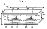
- a magnetic field generator 10 as an embodiment of the present invention is a permanent-magnet type magnetic field generator, and includes a pair of plate yokes 12a and 12b which are faced to each other to provide a gap G in between.
- pair of plate yokes 12a, 12b are two pairs of magnetic poles, i.e. a pair of magnetic poles 14a, 14b which are faced to each other, and another pair of magnetic poles 16a, 16b which are faced to each other.
- the magnetic poles 14a, 14b include permanent magnet groups 18a, 18b respectively, which are disposed on the mutually opposed faces of the pair of plate yokes 12a, 12b.
- the permanent magnet groups 18a, 18b have their respective opposing faces provided with pole pieces 20a, 20b fixed thereon.
- the magnetic poles 16a, 16b include permanent magnet groups 22a, 22b respectively, which are disposed on the mutually opposed faces of the pair of plate yokes 12a, 12b, and the permanent magnet groups 22a, 22b have their respective opposing faces provided with pole pieces 24a, 24b fixed thereon.
- the magnetic poles 14a and 16a have the same polarity (S pole) and the magnetic poles 14b and 16b have the same polarity (N pole).
- This construction generates magnetic fields in the same direction (in an upward direction in the present embodiment as indicated by the arrows) between the magnetic poles 14a, 14b and between the magnetic poles 16a, 16b.
- the permanent magnet groups 18a, 18b are made of rare-earth magnets or ferrite magnets for example, and built by piling magnet blocks into three tiers.
- the blocks are, for example, cubic with a side of 50 mm.
- the same construction is used for the permanent magnet groups 22a and 22b.
- the pole piece 20a includes a disc-like base plate made of iron for example, which is disposed on a main surface of the permanent magnet group 18a.
- the base plate has a main surface provided with a silicon steel plate for prevention of eddy current from developing.
- the silicon steel plate has a laminate construction made of a plurality of block-like units and is fixed onto the base plate with an adhesive.
- the base plate has its circumference region formed with a circular projection which is made of iron for example, for increased magnetic field strength at the circumferential region and improved magnetic field uniformity. Formation of the circular projection creates an inner recess, where a gradient magnetic field coil is disposed. The same arrangement is made for the pole pieces 20b, 24a and 24b.
- the plate yokes 12a and 12b are magnetically connected with each other by a supporting yoke (back yoke) 26 which is attached to respective rear ends of the plate yokes 12a and 12b.
- a magnetic field uniformity space F1 is formed between the pair of pole pieces 20a, 20b and a magnetic field uniformity space F2 is formed between the pair of pole pieces 24a, 24b.
- two magnetic field uniformity spaces F1, F2 are formed in the magnetic field generator 10.
- the “magnetic field uniformity space” refers to a magnetic space formed between a pair of mutually opposed pole pieces in which magnetic field uniformity variation is not greater than 100 ppm.
- the term “center magnetic field strength” refers to a magnetic field strength at a center region of a magnetic field uniformity space.
- each of 160mm DSV magnetic field uniformity spaces F1, F2 has a center magnetic field strength of 0.2215 T.
- the magnetic field generator 10 has a total weight of 8262 kg, including the permanent magnet groups which weigh 1228 kg, the pole pieces which weigh 614 kg, the plate yokes which weigh 4710 kg, and the supporting yoke which weighs 1710 kg.
- the magnetic field generator 10 is a permanent magnet type, unlike those which use electric magnets, no operation for switching electric currents is required.
- By adjusting the magnetic fields generated in the two magnetic field uniformity spaces F1, F2 in advance two highly uniform magnetic fields are obtained at two respective places in a single magnetic field generator 10, and it is possible to sustain the magnetic fields. Therefore, it is possible to obtain e.g. an apparatus which serves as both of a high-quality MRI apparatus and an ESR imaging apparatus, or an MRI apparatus which is capable of taking MRI images of two or more different parts simultaneously.
- a fixed table 28 is provided to pass through between the pair of magnetic poles 14a, 14b and between the pair of magnetic poles 16a, 16b.
- a movable table 30 is disposed on the fixed table 28.
- the movable table 30 is movable on the fixed table 28 longitudinally thereof, and on this movable table 30, a test subject 32 is placed.
- Moving means for the movable table 30 can be a linear motor or an electric cylinder for example.
- position sensors such as Magnescale enables accurate positioning of the movable table 30 and the test subject 32.
- the side on the magnetic poles 14a, 14b is used for MRI image taking whereas the side on the magnetic poles 16a, 16b is used for ESR image taking.
- the test subject 32 when taking MRI images, as shown in Fig. 3, the test subject 32 is placed in the magnetic field uniformity space F1 between the pole pieces 20a, 20b, and then MRI images are taken. Quickly thereafter, the movable table 30 on which the test subject 32 is placed is moved so that the test subject 32 comes in the magnetic field uniformity space F2 between the pole pieces 24a, 24b as shown in Fig. 4, where ESR images are taken.
- MRI imaging can reveal information about the form in the test area
- ESR imaging can reveal chemical information such as locations where radical oxygen is present in the test area, for example. This increases the value of image diagnosis, making the information available for e.g. biopsy of the most malign area of a tumor of a patient, accurate determination of the area to treat, and planning of medical operations.
- the test subject 32 is moved when image taking operation is changed from MRI to ESR.
- the apparatus (plate yokes 12a, 12b, supporting yoke 26, etc.) may be moved instead. In this case, there is no need to perform position adjustment of the test subject 32 since the test subject 32 is not moved and therefore the area to be examined stays lined up.
- the magnetic field strength necessary for ESR image taking may be lower than the magnetic field strength necessary for MRI image taking.
- permanent magnets included in the magnetic poles for ESR image taking may be of a relatively weak magnetic force.
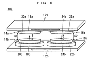
- the permanent magnet groups 18a, 18b may be made of rare-earth magnets whereas in the other pair of the magnetic poles 16a, 16b, the permanent magnet groups 22a, 22b may be made of ferrite magnets. With such an arrangement, it becomes possible to differentiate magnetic field strengths in the two magnetic fields generated by respective pairs of magnetic poles, while keeping the two gaps G1 and G2 the same.
- the examinee 34 lays down on the fixed table 28, placing his head in the magnetic field uniformity space F1 between the pair of pole pieces 20a, 20b, and his feet in the magnetic field uniformity space F2 between the pair of pole pieces 24a, 24b. In this state, MRI images of the head and the feet of the examinee 34 are taken simultaneously.
- diagnosis can become efficient.
- the magnetic poles 14a and 16a have opposing magnetic poles
- the magnetic poles 14b and 16b have opposing magnetic poles so that the direction of magnetic field generated between the pair of magnetic poles 14a, 14b and the direction of magnetic field generated between the pair of magnetic poles 16a, 16b are opposing to each other (differing from each other by 180 degrees).
- the plate yoke 12a may be supported by being suspended from the ceiling for example.
- the direction of magnetic field generated in the magnetic field uniformity space F1 between the pair of pole pieces 20a, 20b and the direction of magnetic field generated in the magnetic field uniformity space F2 between the pair of pole pieces 24a, 24b are different by 180 degrees (opposing relationship), but it is possible to make their strength equal to each other.
- each of the 160mm DSV magnetic field uniformity spaces F1, F2 has a center magnetic field strength of 0.2237 T.
- the weight is 6552 kg, which is 1710 kg lighter than the magnetic field generator 10. Removal of the supporting yoke 26 has another advantage of reduced psychological pressure on the examinee.
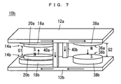
- one pair of the magnetic poles 14a, 14b is constructed just the same as in the previous embodiment.
- the other pair of the magnetic poles 36a, 36b is constructed without permanent magnet groups, with pole pieces 38a, 38b.
- the plate yokes 12a, 12b are connected with each other by two rectangular columns of supporting yokes 40a, 40b and magnetically connected with each other.
- a magnetic circuit as indicated by the arrows is formed, and it is possible to supply part of magnetic flux generated by the magnetic poles 14a, 14b to the other magnetic poles 36a, 36b.
- the central supporting yokes 40a, 40b it is possible to adjust the strength of the magnetic field generated in the gap between the magnetic poles 36a, 36b.
- the 160mm DSV magnetic field uniformity space F1 (formed between the pole pieces 20a, 20b) has a center magnetic field strength of 0.1896 T whereas the 160mm DSV magnetic field uniformity space F2 (formed between the pole pieces 38a, 38b) has a center magnetic field strength of 0.0391 T.
- the magnetic poles 36a, 36b do not use permanent magnet groups, a total amount of magnets used in the construction can be reduced and the magnetic field generator 10b can be lighter accordingly.
- the other pair of magnetic poles 36a, 36b are constructed with the pole pieces 38a, 38b.
- the plate yokes 12a, 12b may be integrally formed with projections at predetermined places therein, to serve as the magnetic poles 36a, 36b.
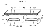
- the supporting yoke may be provided by a supporting yoke 44 which is a pillar-like structure having a through hole 42.
- the fixed table may be disposed, for example, through the through hole 42, so that the test subject can be moved back and forth on the fixed table when taking MRI and ESR images.
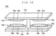
- the supporting yoke may be provided by a supporting yoke 46 which is a pillar-like structure, or as in a magnetic field generator 10e shown in Fig. 10, the supporting yoke may be provided by a supporting yoke 48 which is a cylindrical column.
- FIG. 11 to describe a magnetic field generator 10f as another embodiment.
- the magnetic field generator 10f includes a pair of plate yokes 50a, 50b.
- the plate yokes 50a, 50b have stepped regions 52a, 52b respectively, so when the plate yokes 50a and 50b are faced to each other, a large gap 54 and a small gap 56 are formed.
- the large gap 54 and the small gap 56 are provided with a pair of magnetic poles 14a, 14b and a pair of magnetic poles 16a, 16b respectively, as in the previous embodiments.
- the plate yokes 50a, 50b have stepped regions 52a, 52b respectively, between which a supporting yoke 58 is attached.
- the pair of magnetic poles 16a, 16b which is provided in small gap 56 of the magnetic field generator 10f is effective when the magnetic field uniformity space may be relatively small but the magnetic field strength must be high.
- the gap in each pair of opposed magnetic poles is variable.
- the magnetic field generator 10g includes a plate yoke 60, and plate yokes 60a and 60b which are faced to the plate yoke 60.
- a supporting yoke 62 is erected at a generally center region of the plate yoke 60.
- the plate yokes 60a, 60b are attached to the supporting yoke 62 so that they can slide in vertical directions (toward and away from the plate yoke 60).
- the pair of magnetic poles 14a, 14b are provided between the plate yokes 60, 60a.
- the pair of magnetic poles 16a, 16b are provided between the plate yokes 60, 60b.
- the magnetic field generator 10g it is possible to adjust the size of magnetic field uniformity space, the magnetic field strength and the magnetic field uniformity by adjusting the gap between the magnetic poles 14a, 14b and the gap between the magnetic poles 16a, 16b.
- the magnetic field generator 10h allows padding of the permanent magnet groups so that the gap can be constant.
- the pair of plate yokes 12a, 12b are magnetically connected with each other by a supporting yoke 64.
- a pair of magnetic poles 66a, 66b which are provided on the right hand side of the supporting yoke 64 include padding members 68a, 68b respectively.
- the padding members 68a, 68b are magnetic members, and are provided on the mutually opposed surfaces of the plate yokes 12a, 12b respectively.
- Relatively thin permanent magnet groups 70a, 70b made of rare-earth magnets etc. are formed on the padding members 68a, 68b respectively.
- pole pieces 24a, 24b are provided on mutually opposed surfaces of the thin permanent magnet groups.
- the magnetic field generator 10h it is possible to make the gap between the pole pieces 20a, 20b and the gap between the pole pieces 24a, 24b dimensionally the same, and under this state to make the magnetic fields generated between these gaps have different magnetic field strengths from each other, even if the pair of magnetic poles 14a, 14b include the permanent magnet groups 18a, 18b which are made of rare-earth magnets, and the pair of magnetic poles 66a, 66b include the permanent magnet groups 70a, 70b which are made of rare-earth magnets. Specifically, according to the construction in Fig. 13, the magnetic field strength in the gap between the pole pieces 20a, 20b is higher than the magnetic field strength between the pole pieces 24a, 24b.
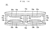
- Fig. 14 shows another magnetic field generator 10i.
- the magnetic field generator 10i includes a pair of generally oval plate yokes 72a, 72b, and the plate yokes 72a, 72b are magnetically connected by four cylindrical columns of supporting yokes 74a through 74d.
- Fig. 15 shows another magnetic field generator 10j.
- the magnetic field generator 10 includes a rotatable supporting yoke 76.
- the supporting yoke 76 is inserted through a pair of plate yokes 78a, 78b which are faced to each other.
- the plate yokes 78a, 78b are rotatable around the supporting yoke 76.
- the pair of magnetic poles 14a, 14b are for MRI image taking
- the pair of magnetic poles 16a, 16b are for ESR image taking.
- the test subject is placed between the magnetic poles 14a, 14b, and MRI images are taken.
- the plate yokes 78a, 78b are rotated by 180 degrees around the supporting yoke 76 to bring the test subject between the pair of magnetic poles 16a, 16b, where ESR images are taken.
- MRI and ESR images can be taken without moving the test subject but by rotating the plate yokes 78a, 78b around the supporting yoke 76.
- the magnetic field generator 10 shown in Fig. 1 may be constructed so that the magnetic field generated between the pair of magnetic poles 14a, 14b and the magnetic field generated between the pair of magnetic poles 16a, 16b have opposing directions from each other.
- the magnetic field generator 10b shown in Fig. 7 may be constructed so that the magnetic field generated between the pair of magnetic poles 14a, 14b and the magnetic field generated between the pair of magnetic poles 36a, 36b have the same direction.
- the magnetic field generators 10c through 10j shown in Fig. 8 through Fig. 15 each include two pairs of magnetic poles.
- the magnetic field generated between one pair of magnetic poles and the magnetic field generated between the other pair of magnetic poles may have the same or reverse directions.
- any of the magnetic field generators described above is applicable not only to an apparatus which serves as both of an MRI apparatus and an ESR imaging apparatus but also to an apparatus which allows MRI image taking at two locations, or to an apparatus which allows ESR image taking at two locations
- the present invention is also applicable to a magnetic field generator which has three or more magnetic field uniformity spaces.
- electromagnetic shielding means such as a grounded Cu plate and Cu net is provided between the spaces.
- the shielding means By providing the shielding means, it becomes possible to prevent quality deterioration of the images, to make shorten the distance between adjacent magnetic field uniformity spaces and to reduce the size of the entire apparatus.
Landscapes
- Physics & Mathematics (AREA)
- Electromagnetism (AREA)
- Engineering & Computer Science (AREA)
- Power Engineering (AREA)
- Condensed Matter Physics & Semiconductors (AREA)
- General Physics & Mathematics (AREA)
- Magnetic Resonance Imaging Apparatus (AREA)
Abstract
Description
Claims (10)
- A permanent-magnet type magnetic field generator which has a plurality of magnetic field uniformity spaces.
- The magnetic field generator according to Claim 1, comprising: a pair of yokes faced to each other with a gap in between; and
at least two pairs of magnetic poles, the poles in each pair being faced with each other between the pair of yokes, wherein
the magnetic field uniformity space is formed between each pair of the magnetic poles. - The magnetic field generator according to Claim 2, wherein the magnetic pole includes a pole piece.
- The magnetic field generator according to Claim 2 or 3, wherein at least part of one yoke in the pair of yokes is movable toward and away from the other yoke.
- The magnetic field generator according to one of Claims 2 through 4, wherein at least a pair of the magnetic poles includes a permanent magnet group.
- The magnetic field generator according to one of Claims 1 through 5, wherein two magnetic field uniformity spaces which are adjacent to each other have different magnetic field strengths from each other.
- The magnetic field generator according to one of Claims 1 through 6, wherein two magnetic field uniformity spaces which are adjacent to each other have their magnetic field directions differing from each other by 180 degrees.
- The magnetic field generator according to one of Claims 2 through 7, wherein two pairs of magnetic poles are provided between the pair of yokes,
one of the pairs of magnetic poles including a permanent magnet group provided by rare-earth magnets, the other pair of magnetic poles including a permanent magnet group provided by ferrite magnets. - The magnetic field generator according to one of Claims 2 through 7, wherein two pairs of magnetic poles are provided between the pair of yokes,
one of the pairs of magnetic poles including a permanent magnet group provided by rare-earth magnets,
the other pair of magnetic poles including a padding member and a permanent magnet group provided by rare-earth magnets which are disposed on a main surface of the padding member. - The magnetic field generator according to one of Claims 1 through 9, wherein electromagnetic shielding means is provided between two magnetic field uniformity spaces which are adjacent to each other.
Applications Claiming Priority (3)
| Application Number | Priority Date | Filing Date | Title |
|---|---|---|---|
| JP2003032111 | 2003-02-10 | ||
| JP2003032111 | 2003-02-10 | ||
| PCT/JP2004/001344 WO2004069052A1 (en) | 2003-02-10 | 2004-02-09 | Magnetic field-producing device |
Publications (3)
| Publication Number | Publication Date |
|---|---|
| EP1593342A1 true EP1593342A1 (en) | 2005-11-09 |
| EP1593342A4 EP1593342A4 (en) | 2009-04-22 |
| EP1593342B1 EP1593342B1 (en) | 2011-12-14 |
Family
ID=32844330
Family Applications (1)
| Application Number | Title | Priority Date | Filing Date |
|---|---|---|---|
| EP04709360A Expired - Lifetime EP1593342B1 (en) | 2003-02-10 | 2004-02-09 | Magnetic field-producing device |
Country Status (5)
| Country | Link |
|---|---|
| US (1) | US20060077027A1 (en) |
| EP (1) | EP1593342B1 (en) |
| JP (2) | JP4419954B2 (en) |
| CN (1) | CN100556359C (en) |
| WO (1) | WO2004069052A1 (en) |
Cited By (2)
| Publication number | Priority date | Publication date | Assignee | Title |
|---|---|---|---|---|
| EP2296546A4 (en) * | 2008-07-08 | 2013-05-22 | Univ Kyushu | MEASURING DEVICE AND METHOD |
| CN107582059A (en) * | 2016-07-06 | 2018-01-16 | 韦伯斯特生物官能(以色列)有限公司 | Magnetic generation circuit for tracking system |
Families Citing this family (25)
| Publication number | Priority date | Publication date | Assignee | Title |
|---|---|---|---|---|
| JP2006204551A (en) * | 2005-01-28 | 2006-08-10 | Kyushu Univ | Biological measuring device and method |
| JP4890945B2 (en) * | 2006-05-29 | 2012-03-07 | 国立大学法人九州大学 | Magnetic resonance imaging system |
| JP5224275B2 (en) * | 2008-03-28 | 2013-07-03 | 日立金属株式会社 | PET / MRI integrated device |
| GB2493164A (en) * | 2011-07-26 | 2013-01-30 | Mervyn Stanley Curtis | Apparatus for applying static or varying magnetic fields across electronic equipment |
| WO2013114993A1 (en) * | 2012-01-30 | 2013-08-08 | 三菱電機株式会社 | Magnetic circuit |
| FR2987433B1 (en) * | 2012-02-28 | 2014-03-28 | Cooltech Applications | MAGNETIC FIELD GENERATOR FOR MAGNETOCALORIC THERMAL APPARATUS |
| GB2501103A (en) * | 2012-04-12 | 2013-10-16 | Mervyn Stanley Curtis | Apparatus applying static or varying magnetic fields across electronic equipment |
| FR2994018B1 (en) * | 2012-07-27 | 2015-01-16 | Cooltech Applications | MAGNETIC FIELD GENERATOR FOR MAGNETOCALORIC THERMAL APPARATUS AND MAGNETOCALORIC THERMAL APPARATUS EQUIPPED WITH SUCH A GENERATOR |
| CN105072990A (en) * | 2013-04-15 | 2015-11-18 | 株式会社东芝 | Magnetic resonance imaging device |
| KR102237125B1 (en) * | 2014-07-16 | 2021-04-08 | 삼성디스플레이 주식회사 | Display apparatus and method for driving the same |
| AU2015311725A1 (en) | 2014-09-05 | 2017-04-20 | Hyperfine Research, Inc. | Thermal management methods and apparatus |
| US10813564B2 (en) | 2014-11-11 | 2020-10-27 | Hyperfine Research, Inc. | Low field magnetic resonance methods and apparatus |
| JPWO2016174993A1 (en) * | 2015-04-28 | 2018-02-22 | 国立大学法人九州大学 | Measuring device |
| JP2018121666A (en) * | 2015-04-28 | 2018-08-09 | 国立大学法人九州大学 | Measuring device and measuring method |
| CN105575583A (en) * | 2016-01-19 | 2016-05-11 | 浙江工业大学 | Magnetic circuit-based magnetic field generator in magnetic-induction free abrasive wire saw cutting |
| US10539637B2 (en) | 2016-11-22 | 2020-01-21 | Hyperfine Research, Inc. | Portable magnetic resonance imaging methods and apparatus |
| US10585153B2 (en) | 2016-11-22 | 2020-03-10 | Hyperfine Research, Inc. | Rotatable magnet methods and apparatus for a magnetic resonance imaging system |
| US10627464B2 (en) | 2016-11-22 | 2020-04-21 | Hyperfine Research, Inc. | Low-field magnetic resonance imaging methods and apparatus |
| CA3043038A1 (en) | 2016-11-22 | 2018-05-31 | Hyperfine Research, Inc. | Systems and methods for automated detection in magnetic resonance images |
| JP6840398B2 (en) * | 2016-12-21 | 2021-03-10 | 株式会社ReMI | Magnetic field application device |
| AU2019274404A1 (en) | 2018-05-21 | 2020-11-12 | Hyperfine Operations, Inc. | B0 magnet methods and apparatus for a magnetic resonance imaging system |
| CN108969911B (en) * | 2018-07-25 | 2020-11-17 | 宋世鹏 | MRI radiotherapy system with double-layer magnetizer |
| US20210110966A1 (en) * | 2019-10-09 | 2021-04-15 | Power Integrations, Inc. | Magnet with multiple discs |
| EP4019995B1 (en) * | 2020-12-22 | 2023-08-16 | Bruker BioSpin GmbH | Epr spectrometer with at least one pole piece made at least partially of a function material |
| CN114023525A (en) * | 2021-11-12 | 2022-02-08 | 中国铁建港航局集团有限公司 | Concrete curing device and curing method based on alternating magnetic field effect |
Family Cites Families (30)
| Publication number | Priority date | Publication date | Assignee | Title |
|---|---|---|---|---|
| GB8401550D0 (en) * | 1984-01-20 | 1984-02-22 | Picker Int Ltd | Nuclear magnetic resonance apparatus |
| DE3566185D1 (en) * | 1984-04-11 | 1988-12-15 | Sumitomo Spec Metals | Magnetic field generating device for nmr-ct |
| JPS60257109A (en) * | 1984-06-01 | 1985-12-18 | Sumitomo Special Metals Co Ltd | Magnetic field generating device |
| JPS61159950A (en) | 1984-12-31 | 1986-07-19 | 株式会社島津製作所 | Magnet for MRI |
| US4668915A (en) * | 1985-03-15 | 1987-05-26 | Honda Giken Kogyo Kabushiki Kaisha | Non-uniform field magnetic resonance dual patient imaging system |
| US4777438A (en) * | 1987-04-27 | 1988-10-11 | Picker International, Inc. | Multiple imaging with improved signal-to-noise ratio |
| US5016638A (en) * | 1989-03-01 | 1991-05-21 | Hsieh Chi H | Vibration control in NMR magnet structures |
| US5023554A (en) * | 1989-05-22 | 1991-06-11 | The Reagents Of The University Of California | Fringe field MRI |
| US5218333A (en) * | 1989-10-02 | 1993-06-08 | Sumitomo Special Metal Co., Ltd. | Magnetic field generating device for use with ESR device |
| GB2244134B (en) * | 1990-04-09 | 1994-08-03 | Elscint Ltd | Superconducting magnet |
| USRE35565E (en) * | 1990-05-18 | 1997-07-22 | Sumitomo Special Metals Co., Ltd. | Magnetic field generating apparatus for MRI |
| JPH04371136A (en) * | 1991-06-19 | 1992-12-24 | Hitachi Medical Corp | Magnetostatic field generating device for mri device |
| JP2757104B2 (en) * | 1993-04-01 | 1998-05-25 | 信越化学工業株式会社 | Magnetic field generator |
| JP3125963B2 (en) * | 1994-03-31 | 2001-01-22 | 山形県 | ESR, NMR shared probe |
| JPH0856919A (en) * | 1994-08-22 | 1996-03-05 | Hitachi Medical Corp | Magnet device |
| JPH08201408A (en) * | 1995-01-31 | 1996-08-09 | Unisia Jecs Corp | Angular velocity detector |
| JPH08294261A (en) * | 1995-04-19 | 1996-11-05 | Daifuku Co Ltd | Rotary actuator |
| DE19709297A1 (en) * | 1996-03-27 | 1997-07-24 | Siemens Ag | Magnet system for diagnostic MRI appts. |
| JP3468637B2 (en) * | 1996-05-13 | 2003-11-17 | 日本電子株式会社 | Nuclear magnetic resonance and electron spin resonance imaging system |
| JPH10234704A (en) * | 1997-02-27 | 1998-09-08 | Hitachi Medical Corp | MRI equipment |
| IT1294051B1 (en) * | 1997-04-29 | 1999-03-15 | Esaote Spa | MAGNETIC STRUCTURE FOR THE GENERATION OF MAGNETIC FIELDS SUITABLE FOR USE IN IMAGE DETECTION IN NUCLEAR MAGNETIC RESONANCE |
| DE19740375A1 (en) * | 1997-09-13 | 1999-03-18 | Philips Patentverwaltung | MR device for Overhauser imaging processes |
| IT1298022B1 (en) * | 1997-12-05 | 1999-12-20 | Esaote Spa | PERMANENT MAGNET FOR IMAGE DETECTION IN NUCLEAR MAGNETIC RESONANCE. |
| JP2000139874A (en) * | 1998-09-02 | 2000-05-23 | Sumitomo Special Metals Co Ltd | Magnetic field generator for MRI |
| US6294915B1 (en) * | 1999-03-23 | 2001-09-25 | General Electric Company | Interior alignment light for open magnet MRI |
| DE60026426T2 (en) * | 1999-11-16 | 2006-11-16 | Neomax Co., Ltd. | Pole piece unit for a magnetic resonance imaging magnet |
| DE10065399A1 (en) * | 2000-12-27 | 2002-07-18 | Siemens Ag | Position of a patient support device within a medical device, e.g. a magnetic resonance tomograph, using a handle for sliding the support along guides, with the handle having an integral brake to aid in positioning |
| US6518867B2 (en) * | 2001-04-03 | 2003-02-11 | General Electric Company | Permanent magnet assembly and method of making thereof |
| US6944492B1 (en) * | 2001-10-01 | 2005-09-13 | Fonar Corporation | Patient bed support for an open MRI system |
| US6853193B2 (en) * | 2002-05-10 | 2005-02-08 | Mayo Foundation For Medical Education And Research | Simultaneous MR data acquisition with multiple mutually desensitized RF coils |
-
2004
- 2004-02-09 JP JP2005504909A patent/JP4419954B2/en not_active Expired - Fee Related
- 2004-02-09 CN CNB2004800096687A patent/CN100556359C/en not_active Expired - Fee Related
- 2004-02-09 US US10/544,711 patent/US20060077027A1/en not_active Abandoned
- 2004-02-09 EP EP04709360A patent/EP1593342B1/en not_active Expired - Lifetime
- 2004-02-09 WO PCT/JP2004/001344 patent/WO2004069052A1/en not_active Ceased
-
2009
- 2009-09-08 JP JP2009207394A patent/JP4826929B2/en not_active Expired - Fee Related
Cited By (3)
| Publication number | Priority date | Publication date | Assignee | Title |
|---|---|---|---|---|
| EP2296546A4 (en) * | 2008-07-08 | 2013-05-22 | Univ Kyushu | MEASURING DEVICE AND METHOD |
| US8532740B2 (en) | 2008-07-08 | 2013-09-10 | Kyushi University | Measurement device and measurement method |
| CN107582059A (en) * | 2016-07-06 | 2018-01-16 | 韦伯斯特生物官能(以色列)有限公司 | Magnetic generation circuit for tracking system |
Also Published As
| Publication number | Publication date |
|---|---|
| WO2004069052A1 (en) | 2004-08-19 |
| EP1593342B1 (en) | 2011-12-14 |
| US20060077027A1 (en) | 2006-04-13 |
| JP4826929B2 (en) | 2011-11-30 |
| JP2009291639A (en) | 2009-12-17 |
| CN100556359C (en) | 2009-11-04 |
| JPWO2004069052A1 (en) | 2006-05-25 |
| JP4419954B2 (en) | 2010-02-24 |
| EP1593342A4 (en) | 2009-04-22 |
| CN1771006A (en) | 2006-05-10 |
Similar Documents
| Publication | Publication Date | Title |
|---|---|---|
| EP1593342B1 (en) | Magnetic field-producing device | |
| US11726155B2 (en) | B0 magnet methods and apparatus for a magnetic resonance imaging system | |
| EP0760484B1 (en) | Opposed magnet-type magnetic circuit assembly with permanent magnets | |
| US7071694B1 (en) | Magnet assembly of an MRI system with concentric annular ferromagnetic laminations | |
| JPH07171131A (en) | Improvement of MRI magnet | |
| EP0924530A3 (en) | MRI gradient coil assembly | |
| WO2005124381A8 (en) | Magnetic resonance imaging system with iron-assisted magnetic field gradient system | |
| KR20000075747A (en) | Mri magnetic field generator | |
| US20020060569A1 (en) | Magnetic resonance imaging apparatus | |
| JPH1028682A (en) | Magnet device for diagnostic magnetic resonance equipment | |
| EP1524531A2 (en) | System and method for adjusting magnetic center field for permanent mri magnetic field generator | |
| JPH10146326A (en) | Magnetic field generator for MRI | |
| JP2000357608A (en) | Magnetic field generator | |
| JP3372098B2 (en) | Static magnetic field generator for magnetic resonance imaging | |
| JP3906418B2 (en) | Magnetic field generator for MRI | |
| JP2003153879A (en) | Gradient magnetic field generating coil and magnetic field generator for MRI | |
| JP2022520767A5 (en) | ||
| US10859649B2 (en) | Vibration reduction for a magnetic resonance imaging apparatus | |
| JP2003052662A (en) | Magnetic resonance imaging equipment | |
| JPH05152120A (en) | Magnetic-field generation apparatus and adjusting method for magnetic-field uniformity | |
| JPH05144628A (en) | Magnetic field generator | |
| JPS62250609A (en) | Magnetic field generator | |
| JPS62176107A (en) | Magnet for nuclear magnetic resonance diagnostic tester | |
| JPH02219204A (en) | Magnetic field generating apparatus | |
| WO1999033398A1 (en) | Mri magnetic field generator |
Legal Events
| Date | Code | Title | Description |
|---|---|---|---|
| PUAI | Public reference made under article 153(3) epc to a published international application that has entered the european phase |
Free format text: ORIGINAL CODE: 0009012 |
|
| 17P | Request for examination filed |
Effective date: 20050810 |
|
| AK | Designated contracting states |
Kind code of ref document: A1 Designated state(s): AT BE BG CH CY CZ DE DK EE ES FI FR GB GR HU IE IT LI LU MC NL PT RO SE SI SK TR |
|
| AX | Request for extension of the european patent |
Extension state: AL LT LV MK |
|
| RAP1 | Party data changed (applicant data changed or rights of an application transferred) |
Owner name: NEOMAX CO., LTD. |
|
| DAX | Request for extension of the european patent (deleted) | ||
| RBV | Designated contracting states (corrected) |
Designated state(s): DE GB IT NL |
|
| RAP1 | Party data changed (applicant data changed or rights of an application transferred) |
Owner name: HITACHI METALS, LTD. |
|
| A4 | Supplementary search report drawn up and despatched |
Effective date: 20090319 |
|
| 17Q | First examination report despatched |
Effective date: 20090826 |
|
| R17C | First examination report despatched (corrected) |
Effective date: 20100111 |
|
| R17C | First examination report despatched (corrected) |
Effective date: 20100111 |
|
| GRAP | Despatch of communication of intention to grant a patent |
Free format text: ORIGINAL CODE: EPIDOSNIGR1 |
|
| GRAS | Grant fee paid |
Free format text: ORIGINAL CODE: EPIDOSNIGR3 |
|
| GRAA | (expected) grant |
Free format text: ORIGINAL CODE: 0009210 |
|
| AK | Designated contracting states |
Kind code of ref document: B1 Designated state(s): DE GB IT NL |
|
| REG | Reference to a national code |
Ref country code: GB Ref legal event code: FG4D |
|
| REG | Reference to a national code |
Ref country code: DE Ref legal event code: R096 Ref document number: 602004035661 Country of ref document: DE Effective date: 20120209 |
|
| REG | Reference to a national code |
Ref country code: NL Ref legal event code: VDEP Effective date: 20111214 |
|
| PG25 | Lapsed in a contracting state [announced via postgrant information from national office to epo] |
Ref country code: NL Free format text: LAPSE BECAUSE OF FAILURE TO SUBMIT A TRANSLATION OF THE DESCRIPTION OR TO PAY THE FEE WITHIN THE PRESCRIBED TIME-LIMIT Effective date: 20111214 |
|
| PLBE | No opposition filed within time limit |
Free format text: ORIGINAL CODE: 0009261 |
|
| STAA | Information on the status of an ep patent application or granted ep patent |
Free format text: STATUS: NO OPPOSITION FILED WITHIN TIME LIMIT |
|
| 26N | No opposition filed |
Effective date: 20120917 |
|
| GBPC | Gb: european patent ceased through non-payment of renewal fee |
Effective date: 20120314 |
|
| PG25 | Lapsed in a contracting state [announced via postgrant information from national office to epo] |
Ref country code: IT Free format text: LAPSE BECAUSE OF FAILURE TO SUBMIT A TRANSLATION OF THE DESCRIPTION OR TO PAY THE FEE WITHIN THE PRESCRIBED TIME-LIMIT Effective date: 20111214 |
|
| REG | Reference to a national code |
Ref country code: DE Ref legal event code: R097 Ref document number: 602004035661 Country of ref document: DE Effective date: 20120917 |
|
| PG25 | Lapsed in a contracting state [announced via postgrant information from national office to epo] |
Ref country code: GB Free format text: LAPSE BECAUSE OF NON-PAYMENT OF DUE FEES Effective date: 20120314 |
|
| PGFP | Annual fee paid to national office [announced via postgrant information from national office to epo] |
Ref country code: DE Payment date: 20180130 Year of fee payment: 15 |
|
| REG | Reference to a national code |
Ref country code: DE Ref legal event code: R119 Ref document number: 602004035661 Country of ref document: DE |
|
| PG25 | Lapsed in a contracting state [announced via postgrant information from national office to epo] |
Ref country code: DE Free format text: LAPSE BECAUSE OF NON-PAYMENT OF DUE FEES Effective date: 20190903 |