EP1593326A1 - Dispensing device for stacked articles - Google Patents
Dispensing device for stacked articles Download PDFInfo
- Publication number
- EP1593326A1 EP1593326A1 EP04010645A EP04010645A EP1593326A1 EP 1593326 A1 EP1593326 A1 EP 1593326A1 EP 04010645 A EP04010645 A EP 04010645A EP 04010645 A EP04010645 A EP 04010645A EP 1593326 A1 EP1593326 A1 EP 1593326A1
- Authority
- EP
- European Patent Office
- Prior art keywords
- capsule
- passage
- stop means
- stop
- capsules
- Prior art date
- Legal status (The legal status is an assumption and is not a legal conclusion. Google has not performed a legal analysis and makes no representation as to the accuracy of the status listed.)
- Granted
Links
- 239000002775 capsule Substances 0.000 claims abstract description 132
- 230000005540 biological transmission Effects 0.000 claims description 14
- 230000005484 gravity Effects 0.000 claims description 2
- 238000011084 recovery Methods 0.000 claims description 2
- 230000033001 locomotion Effects 0.000 description 16
- 230000000694 effects Effects 0.000 description 6
- 235000013305 food Nutrition 0.000 description 5
- 208000031968 Cadaver Diseases 0.000 description 3
- 238000002360 preparation method Methods 0.000 description 3
- 235000013361 beverage Nutrition 0.000 description 2
- 238000010276 construction Methods 0.000 description 2
- 238000012423 maintenance Methods 0.000 description 2
- 230000014759 maintenance of location Effects 0.000 description 2
- 230000004913 activation Effects 0.000 description 1
- XAGFODPZIPBFFR-UHFFFAOYSA-N aluminium Chemical compound [Al] XAGFODPZIPBFFR-UHFFFAOYSA-N 0.000 description 1
- 229910052782 aluminium Inorganic materials 0.000 description 1
- 238000004140 cleaning Methods 0.000 description 1
- 239000002131 composite material Substances 0.000 description 1
- 238000006073 displacement reaction Methods 0.000 description 1
- 239000002985 plastic film Substances 0.000 description 1
- 229920006255 plastic film Polymers 0.000 description 1
Images


Classifications
-
- A—HUMAN NECESSITIES
- A47—FURNITURE; DOMESTIC ARTICLES OR APPLIANCES; COFFEE MILLS; SPICE MILLS; SUCTION CLEANERS IN GENERAL
- A47F—SPECIAL FURNITURE, FITTINGS, OR ACCESSORIES FOR SHOPS, STOREHOUSES, BARS, RESTAURANTS OR THE LIKE; PAYING COUNTERS
- A47F1/00—Racks for dispensing merchandise; Containers for dispensing merchandise
- A47F1/04—Racks or containers with arrangements for dispensing articles, e.g. by means of gravity or springs
- A47F1/08—Racks or containers with arrangements for dispensing articles, e.g. by means of gravity or springs dispensing from bottom
- A47F1/10—Racks or containers with arrangements for dispensing articles, e.g. by means of gravity or springs dispensing from bottom having mechanical dispensing means, e.g. with buttons or handles
Definitions
- the present invention relates to a capsule selection device contained in a stack.
- the invention is aimed in particular at the supply and the distribution of food-grade capsules such as in distributors, beverage machines of the type coffee machines or other types of machines.
- capsules may be, for example, portioned packages of configuration, sizes and / or natures very variable. It can be capsules in plastic film, filter paper, aluminum or composite laminate and may be lens shape, scoop or take other forms.
- a reserve of capsule can be constituted in the form a stack in a reserved space and serve for the supply of capsules according to needs.
- US Pat. No. 6,595,106 relates to a capsule magazine to store several capsules stacked on top of each other.
- the capsules can be removed from the store on request by an opening practiced at the base of the store.
- a disadvantage is that capsules must be removed manually.
- Such a configuration meets the requirements of a device that is reliable.
- the first capsule is maintained stably in several places distributed; which avoids tipping during the release of the capsule and the possible jamming of the capsule.
- the first stopping means are at least number of three or four regularly distributed around the perimeter of the passage.
- the stability of the capsule is greatly improved when the means of stopping are sufficient in number.
- the number and distribution of these means of arrest around the passage promotes the descent of the capsule so as to avoid the cross-positioning and jamming that may result, in particular, to the output of the device.
- the shape of the stop means proves to be important in particular for ensure good support in a horizontal plane and thus avoid a release of through the capsule.
- the first stop means are formed of fingers configured to create lines or bearing surfaces under the extending capsule substantially towards the center of the passage in the off position.
- the first stop means ends with free ends which are movable to describe an arc portion. So, the movement of the stop means is similar to that of a diaphragm so that when the capsule is released, the pressure on the capsule is gradually reduced and distributed around the capsule. This helps to maintain the capsule stable and to release it by avoiding the capsule to go wrong.
- each first stop means is attached to a rod of transmission rotatably mounted on the body in the vicinity of the periphery of the passage.
- a rod of transmission rotatably mounted on the body in the vicinity of the periphery of the passage.
- the device comprises second stop means which are configured to retain the second capsule located above of the first capsule in the pile at the moment when the first stop means are in the release position to release the first capsule. So, first and second stop means synchronously cooperate to release the first capsule in a selective manner by ensuring the maintenance of the other capsules in the battery. This synchronization contributes to the reliability of the system and guarantees its good operation; which makes it possible to envisage its use in any type of system distribution, including, an automated system with payment system or not.
- the second stopping means extend transversely towards the interior of the passage, so as to simultaneous stop position, to form several support points distributed under the second capsule. Indeed, it is also important to keep the stack of capsules at above the first capsule as stable as possible and to avoid this one from position wrongly. A bad positioning can indeed affect the free descent of the capsules in the space assigned to them, as in a tube by example. A bad positioning of the second capsule can still make its descent against the first means of stopping incorrect.
- the second means of arrest are at least three or four regularly around the perimeter of the passage.
- the second stop means ends preferably with free ends that are movable by describing an arc portion.
- the down the second capsule is by a diaphragm effect that ensures a horizontal descent and reduces the risk of jamming.
- each second stop means is attached to a transmission rod mounted in rotation on the body in the vicinity of the periphery of the passage; which rod is the same as that for each first stop means.
- a transmission rod mounted in rotation on the body in the vicinity of the periphery of the passage; which rod is the same as that for each first stop means.
- each first and second stop means are thus attached to a transmission rod forming together, transversely to the passage, an "L" so as to take positions stopping in opposition of phases.
- Such a construction has the effect of ensuring good timing in the release and support of the capsules while now the number of coins used as low as possible.
- the transmission rods are operated in concert by means of a ring lodged around the perimeter of the passage; which is actuated alternately between the stop positions of the first and second stop means.
- This principle ensures that all the first means of stopping are actuated at the same time and that all the second stop means are actuated at the same time but to move in phase opposition with respect to movements of the first stop means.
- Such a device can be actuated by actuating means of any type.
- the actuating means comprise means solenoid type electric.
- the actuating means also include crankshaft type mechanical means. He is heard that the electric means could be replaced by a manual control lever type, drawer or other.
- the present invention relates to a device for selecting capsules of the type of that shown in Figs 1 and 2, as a preferred example, and referenced in 1.
- Each capsule contains a dose of food product such as ground coffee example.
- the device 1 therefore comprises a body 10 on which the elements are mounted, the body 10 delimits a passage 20 of size section and shape adapted to the passage of the capsules.
- the passage 20 is typically arranged in look at a reserve of capsules located above the passage and coaxially in relation to this one. Such a reserve of capsules can be presented under the form of a capsule stack contained in a container as shown in FIG. Fig. 8, as will be detailed later in the description.
- the device comprises first stop means 3 and second means stop 4; which means 3, 4 are arranged at two different levels in the passage 20.
- the first stop means 3 serve to maintain the first capsule in the pile up before his release.
- the first capsule is understood as being the capsule that is able to be released by the first stop means.
- the seconds stop means 4 serve to hold the capsule that follows this first capsule, when the first capsule is released by the first stop means.
- the capsule The following is therefore called a "second capsule" in the present application for reasons for clarity.
- the first stop means 3 comprise a series of stop elements in finger shape 30, 31, 32, 33 which are distributed around the periphery of the passage 20. These elements are at least three or four in number to ensure stability and sufficient maintenance of the capsule.
- the number of stop elements depends on the size and / or the shape of the capsule. For example, for lenticular capsule and relatively wide, of the order of 40 mm in diameter or more, the number of elements stopping is preferably at least four, evenly distributed over the around the passage, for example, about 90 degrees between two elements.
- the stop elements provide support to the capsule on a surface 300 or a line which extends in the deployed position towards the interior of the passage.
- Second stop means 4 in the form of stop elements 40, 41, 42, 43 of substantially the same shape are provided at a vertical distance of about one capsule thickness above the stop elements 30, 31, 32, 34 of the first means.
- the first and second stop means are respectively mounted by pair 30, 40; 31, 41; 32, 42; 33, 43 on transmission rods 50, 51, 52, 53.
- Each pair is mounted to form an "L" oriented transversely compared to the passage.
- the transmission rods 50, 51, 52, 53 are mounted in rotation relative to the body along an axis passing through their center O. All rods transmission are also connected to each other by a transmission ring 6 which is configured to move the rotating rods when the ring is itself biased in reciprocating motion relative to the center of the passage.
- the rods comprise a base 501 which is fixed to the ring by a pivot point along an axis O 'offset externally with respect to the axis O, thus allowing to transmit the rotational movement to the rod during the pivoting movement of the ring.
- Each rod is finally mounted in a oblong slot 60 of the ring which provides guidance in rotation of the rod.
- the ring comprises a series of oblong light 61 traversed by elements of 150 fixing connected to the body. The ring can thus pivot in a guided manner by to the elements 50, 51, 52, 150 of an amplitude determined by the length of the lights. This amplitude is thus a function of the amplitude of movements of the first and second stop elements to perform their stop and release of the capsules.
- actuating means 8 which can understand an electrically controlled system such as a solenoid 80.
- a solenoid 80 Such a system is able to transmit after receiving an electrical impulse a linear movement back and forth by means of a piston 81.
- This piston 81 is hinged on a crankshaft 82 that turns this linear movement of the piston into motion transmitted to a shaft 83 at the axis O ".
- This circular motion of the shaft 83 is transmitted to the ring 6 by a lever arm 84 which is fixed in rotation according to O "'on an extension 62 of the ring 6.
- Solenoid piston return control can be either by electrical impulse either by a return spring (not shown).
- first and second stop means have free ends, respectively, 300, 400, opposed to those mounted on the rod of transmission and which therefore move according to an arc portion.
- This portion of arc intersects with the edge 21 of the passage 20 and extends towards the interior of the passage so that the stop means retract by reducing support with the capsule, from the inside 22 to the edge 21 of the passage, in the manner a diaphragm.
- Figs. 3 and 4 show the retention of a first capsule 90 on the first stop means 3 when they are deployed in position towards the interior of the passage.
- the piston of the solenoid is then in the retracted position.
- the second stop means are in the release position; which allows the stack of capsules to come into contact with the first capsule 90.
- the stack of capsules, except for the first capsule is not represented. Pulling in the direction T, the piston causes the ring in the pivoting direction A; which effect of transmitting rotational movement R1 to the transmission rods and therefore to deploy the first stop elements 3.
- FIGs. 5 and 6 show the retention of a second capsule 91 while FIG. 7 shows the release of the first capsule 90; these figures however showing the device in the same configuration means stop.
- the first stop means 3 are then retracted; which leads to the second stopping means 4 in the extended position to retain the second capsule 91 in the stack at the moment of the release of the first capsule 90.
- the passage in this new configuration is obtained by actuation of the actuating means, in particular of the piston which takes an extended position.
- the piston By pushing in the direction P, the piston causes the ring in the pivoting direction B; which has the effect of transmit a rotational movement R2 to the transmission rods and thus to make deploying the second stop elements 4.
- This deployment has the effect of preventing the descent of the stack of capsules while the first capsule 90 is released.
- the device returns to the mode of Figs. 3-4 by return of the piston in the retracted position to bring down the second capsule 91 in contact with the first stop means 3; which then becomes the new first capsule selectable to be released at the desired time.
- the return of the piston can be done by a return spring, for example.
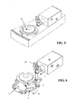
- FIG. 8 represents a dispensing device 2 of capsules from capsules stacked in a charging system that uses the selection device 1 according to the invention.
- the dispensing device 2 comprises a system of loading 7 comprising a removable tube 70 connecting to a portion of a tube buffer 71 permanently mounted on the body 10 of the selection device.
- the buffer tube holder 71 is able to receive a number of capsules to allow the removable tube 70 to be able to perform the replacement in capsules.
- the removable tube 70 and the tube support 71 can be associated by alignment means 72 whose function is to make it possible to connect the tube detachable 70 to the tube support 71 quickly and without dropping capsules off the system.
- a set of recovering capsules 73 comprising a first ramp 74 configured to orient the capsule on a second ramp 75 defining a clearance 76 for the recovery of the capsule.
- the second ramp includes a rim 77 to stop the sliding of the capsule.
- Ramps 75, 76 are positioned so as to have opposite sliding surfaces to ensure better inviolability of the device.
- the dispensing device can be associated with a means of command such as a command button that controls the actuating means and a payment system for activation of the control means (no shown).
- the payment system can be made by a coin mechanism and / or payment module by magnetic card or smart card or by means of remote payment such as telecommunication and / or multimedia.
Landscapes
- Vending Machines For Individual Products (AREA)
- Apparatus For Making Beverages (AREA)
- Control And Other Processes For Unpacking Of Materials (AREA)
- Seasonings (AREA)
- De-Stacking Of Articles (AREA)
- Supplying Of Containers To The Packaging Station (AREA)
- Filtering Of Dispersed Particles In Gases (AREA)
- Basic Packing Technique (AREA)
- Transition And Organic Metals Composition Catalysts For Addition Polymerization (AREA)
- Paper (AREA)
Abstract
Description
La présente invention se rapporte à un dispositif de sélection de capsules contenues dans un empilement. L'invention vise en particulier l'approvisionnement et la distribution de capsules du type alimentaire comme dans les distributeurs, les machines de boissons du type machines à café ou autres types de machines.The present invention relates to a capsule selection device contained in a stack. The invention is aimed in particular at the supply and the distribution of food-grade capsules such as in distributors, beverage machines of the type coffee machines or other types of machines.
Dans le domaine alimentaire, l'utilisation de systèmes de préparation de produits alimentaires à partir de capsules, tels que des machines de distribution de boissons, est en pleine expansion en raison des nombreux avantages qu'apportent généralement ces systèmes. Ces systèmes peuvent être des machines de distribution de boissons, par exemple, qui fonctionnent en utilisant des capsules contenant une base de boisson. Le consommateur peut se préparer une boisson en utilisant ces capsules de manière simple, rapide et la plupart du temps avec un minimum d'intervention pour la préparation et/ou le nettoyage.In the food sector, the use of food preparation systems food products from capsules, such as dispensing machines drinks, is booming because of the many benefits that come with usually these systems. These systems can be machines of distribution of beverages, for example, that operate using capsules containing a drink base. The consumer can prepare a drink in using these capsules in a simple, fast way and most of the time with a minimum intervention for preparation and / or cleaning.
Ces capsules peuvent être, par exemple, des emballages portionnés de configuration, de tailles et/ou de natures très variables. Il peut s'agir de capsules en film plastique, en papier filtre, en aluminium ou laminé composite et peuvent être en forme de lentille, de godet ou prendre d'autres formes.These capsules may be, for example, portioned packages of configuration, sizes and / or natures very variable. It can be capsules in plastic film, filter paper, aluminum or composite laminate and may be lens shape, scoop or take other forms.
Dans le cas d'une utilisation intensive de ces machines, il existe un besoin pour disposer de réserves suffisantes en capsules afin d'éviter la rupture de stock et/ou offrir un choix plus large de différentes capsules pour la préparation de spécialités différentes. Pour cela, une réserve de capsule peut être constituée sous la forme d'une pile dans un espace réservé et servir à l'approvisionnement en capsules selon les besoins.In the case of intensive use of these machines, there is a need for have sufficient reserves in capsules to avoid stock-out and / or offer a wider choice of different capsules for the preparation of specialties different. For this purpose, a reserve of capsule can be constituted in the form a stack in a reserved space and serve for the supply of capsules according to needs.
Par exemple, le brevet US 6,595,106 se rapporte à un magasin pour capsules permettant de stocker plusieurs capsules empilées les unes sur les autres. Les capsules peuvent ainsi être retirées du magasin sur demande par une ouverture pratiquée à la base du magasin. Un inconvénient provient de ce que les capsules doivent être retirées manuellement.For example, US Pat. No. 6,595,106 relates to a capsule magazine to store several capsules stacked on top of each other. The capsules can be removed from the store on request by an opening practiced at the base of the store. A disadvantage is that capsules must be removed manually.
Il existe donc un besoin pour disposer d'un dispositif de sélection de capsules à
partir d'une pile de capsules qui soit automatisé. Toutefois, un tel dispositif doit
permettre de libérer chaque capsule de manière fiable et sur un très grand nombre
de cycles. Il doit aussi être de conception simple, d'actionnement rapide mais pouvoir
s'adapter à des capsules de tailles et formes différentes. Certaines capsules de
forme aplatie ont tendance à mal se positionner et la libération de ces capsules à
partir d'une pile pose problème. Aussi, le dispositif doit permettre de prendre en
charge la libération des capsules de manière à éviter les coincements et la mise de
travers des capsules.
Pour cela, l'invention concerne, un dispositif de sélection de capsules à partir d'une
pile de capsules contenue dans un conteneur comprenant:
For this purpose, the invention relates to a device for selecting capsules from a stack of capsules contained in a container comprising:
Une telle configuration répond aux exigences d'un dispositif qui soit fiable. Ainsi, la première capsule est maintenue de manière stable en plusieurs endroits répartis; ce qui évite le basculement lors de la libération de la capsule et le coincement possible de la capsule.Such a configuration meets the requirements of a device that is reliable. Thus, the first capsule is maintained stably in several places distributed; which avoids tipping during the release of the capsule and the possible jamming of the capsule.
De manière préférentielle, les premiers moyens d'arrêt sont au moins au nombre de trois ou quatre répartis régulièrement sur le pourtour du passage. En effet, la stabilité de la capsule est fortement améliorée lorsque les moyens d'arrêt sont en nombre suffisant. De plus, le nombre et la répartition de ces moyens d'arrêt autour du passage favorise la descente de la capsule de manière à éviter les positionnements de travers et coincements pouvant en résulter, notamment, à la sortie du dispositif.Preferably, the first stopping means are at least number of three or four regularly distributed around the perimeter of the passage. In Indeed, the stability of the capsule is greatly improved when the means of stopping are sufficient in number. In addition, the number and distribution of these means of arrest around the passage promotes the descent of the capsule so as to avoid the cross-positioning and jamming that may result, in particular, to the output of the device.
De plus, la forme des moyens d'arrêt s'avère être importante notamment pour assurer un bon maintien selon un plan horizontal et éviter ainsi une libération de travers de la capsule. Pour cela, les premiers moyens d'arrêt sont formés de doigts configurés pour créer des lignes ou surfaces d'appui sous la capsule s'étendant sensiblement vers le centre du passage en position d'arrêt.In addition, the shape of the stop means proves to be important in particular for ensure good support in a horizontal plane and thus avoid a release of through the capsule. For this, the first stop means are formed of fingers configured to create lines or bearing surfaces under the extending capsule substantially towards the center of the passage in the off position.
De manière préférentielle, les premiers moyens d'arrêt se terminent par des extrémités libres qui sont mobiles de manière à décrire une portion d'arc. Ainsi, le déplacement des moyens d'arrêt s'apparente à celle d'un diaphragme de sorte que lors de la libération de la capsule, l'appui sur la capsule se réduit progressivement et de manière répartie autour de la capsule. Ceci contribue à maintenir la capsule stable et à la libérer en évitant à la capsule de partir de travers.Preferably, the first stop means ends with free ends which are movable to describe an arc portion. So, the movement of the stop means is similar to that of a diaphragm so that when the capsule is released, the pressure on the capsule is gradually reduced and distributed around the capsule. This helps to maintain the capsule stable and to release it by avoiding the capsule to go wrong.
De préférence, chaque premier moyen d'arrêt est rattaché à une tige de transmission montée en rotation sur le corps au voisinage de la périphérie du passage. Un tel montage est ainsi particulièrement simple et fiable.Preferably, each first stop means is attached to a rod of transmission rotatably mounted on the body in the vicinity of the periphery of the passage. Such an assembly is thus particularly simple and reliable.
Selon un autre aspect de l'invention, le dispositif comprend des seconds moyens d'arrêt qui sont configurés pour retenir la seconde capsule située au dessus de la première capsule dans la pile au moment où les premiers moyens d'arrêt sont en position de libération pour libérer la première capsule. Ainsi, les premiers et second moyens d'arrêt coopèrent de manière synchronisée pour libérer la première capsule de manière sélective en assurant le maintien des autres capsules dans la pile. Cette synchronisation participe à la fiabilité du système et garantit son bon fonctionnement; ce qui permet d'envisager son utilisation dans tout type de système de distribution, y compris, un système automatisé avec système de paiement ou non.According to another aspect of the invention, the device comprises second stop means which are configured to retain the second capsule located above of the first capsule in the pile at the moment when the first stop means are in the release position to release the first capsule. So, first and second stop means synchronously cooperate to release the first capsule in a selective manner by ensuring the maintenance of the other capsules in the battery. This synchronization contributes to the reliability of the system and guarantees its good operation; which makes it possible to envisage its use in any type of system distribution, including, an automated system with payment system or not.
De la même manière que pour les premiers moyens d'arrêt, les seconds moyens d'arrêt se déploient transversalement vers l'intérieur du passage, de manière simultanée en position d'arrêt, pour former plusieurs points d'appuis répartis sous la seconde capsule. En effet, il est aussi important de maintenir la pile de capsules au dessus de la première capsule aussi stable que possible et éviter à celle-ci de se positionner de travers. Un mauvais positionnement peut en effet affecter la libre descente des capsules dans l'espace qui leur est affecté, comme dans un tube par exemple. Un mauvais positionnement de la seconde capsule peut encore rendre sa descente contre les premiers moyens d'arrêt incorrect.In the same way as for the first stop means, the second stopping means extend transversely towards the interior of the passage, so as to simultaneous stop position, to form several support points distributed under the second capsule. Indeed, it is also important to keep the stack of capsules at above the first capsule as stable as possible and to avoid this one from position wrongly. A bad positioning can indeed affect the free descent of the capsules in the space assigned to them, as in a tube by example. A bad positioning of the second capsule can still make its descent against the first means of stopping incorrect.
De la même manière que pour les premiers moyens d'arrêt, les seconds moyens d'arrêts sont au moins au nombre de trois ou quatre répartis régulièrement sur le pourtour du passage.In the same way as for the first stop means, the second means of arrest are at least three or four regularly around the perimeter of the passage.
De même, les seconds moyens d'arrêt se terminent préférentiellement par des extrémités libres qui sont mobiles en décrivant une portion d'arc. De la sorte, la descente de la seconde capsule se fait par un effet de diaphragme qui assure une descente horizontale et réduit le risque de coincement.Likewise, the second stop means ends preferably with free ends that are movable by describing an arc portion. In this way, the down the second capsule is by a diaphragm effect that ensures a horizontal descent and reduces the risk of jamming.
Aussi, chaque second moyen d'arrêt est rattaché à une tige de transmission montée en rotation sur le corps au voisinage de la périphérie du passage; laquelle tige est la même que celle pour chaque premier moyen d'arrêt. Une telle configuration participe à la fois à la garantie d'une parfaite synchronisation des mouvements des premiers et seconds moyens d'arrêt. De plus, chaque premier et second moyens d'arrêt sont ainsi rattachés à une tige de transmission en formant ensemble, transversalement au passage, un "L" de façon à prendre des positions d'arrêt en opposition de phases. Une telle construction a pour effet d'assurer une bonne synchronisation dans la libération et la prise en charge des capsules tout en maintenant le nombre de pièces utilisées aussi bas que possible.Also, each second stop means is attached to a transmission rod mounted in rotation on the body in the vicinity of the periphery of the passage; which rod is the same as that for each first stop means. Such a configuration contributes to both the guarantee of a perfect synchronization of movements of the first and second stop means. In addition, each first and second stop means are thus attached to a transmission rod forming together, transversely to the passage, an "L" so as to take positions stopping in opposition of phases. Such a construction has the effect of ensuring good timing in the release and support of the capsules while now the number of coins used as low as possible.
Selon un principe de construction avantageux, les tiges de transmission sont actionnées de concert au moyen d'une bague logée sur le pourtour du passage; laquelle est actionnée de manière alternative entre les positions d'arrêt des premiers et seconds moyens d'arrêt. Ce principe assure que tous les premiers moyens d'arrêt sont actionnés en même temps et que tous les second moyens d'arrêt sont actionnés en même temps mais pour se mouvoir en opposition de phases par rapport aux mouvements des premiers moyens d'arrêt.According to an advantageous construction principle, the transmission rods are operated in concert by means of a ring lodged around the perimeter of the passage; which is actuated alternately between the stop positions of the first and second stop means. This principle ensures that all the first means of stopping are actuated at the same time and that all the second stop means are actuated at the same time but to move in phase opposition with respect to movements of the first stop means.
Un tel dispositif peut être actionné par des moyens d'actionnement de tout type. Dans un mode possible, les moyens d'actionnement comprennent des moyens électriques du type à solénoïde. Dans un mode possible, les moyens d'actionnement comprennent aussi des moyens mécaniques du type à vilebrequin. Il est entendu que les moyens électriques pourraient être remplacés par une commande manuelle du type à levier, tiroir ou autres.Such a device can be actuated by actuating means of any type. In one possible mode, the actuating means comprise means solenoid type electric. In a possible mode, the actuating means also include crankshaft type mechanical means. He is heard that the electric means could be replaced by a manual control lever type, drawer or other.
Ces caractéristiques et leurs avantages ainsi que d'autres possibles pourront
être mieux compris à la lumière de la description qui suit et des dessins qui suivent:
La présente invention se rapporte à un dispositif de sélection de capsules du
type de celui figurant aux Figs 1 et 2, à titre d'exemple préférentiel, et référencé en 1.
Chaque capsule contient une dose de produit alimentaire tel que du café moulu par
exemple. Le dispositif 1 comprend donc un corps 10 sur lequel les éléments
principaux sont montés, le corps 10 délimite un passage 20 de section de taille et de
forme adaptée au passage des capsules. Le passage 20 est typiquement disposé en
regard d'une réserve de capsules située au dessus du passage et de manière coaxiale
par rapport à celui-ci. Une telle réserve de capsules peut se présenter sous la
forme d'un empilement en capsules contenu dans un conteneur comme le montre la
Fig. 8, comme il sera détaillé plus loin dans la description.The present invention relates to a device for selecting capsules of the
type of that shown in Figs 1 and 2, as a preferred example, and referenced in 1.
Each capsule contains a dose of food product such as ground coffee
example. The
Le dispositif comprend des premiers moyens d'arrêt 3 et des second moyens
d'arrêt 4; lesquels moyens 3, 4 sont disposés à deux niveaux différents dans le
passage 20. Les premiers moyens d'arrêt 3 servent à maintenir la première capsule
dans la pile en place avant sa libération. La première capsule s'entend comme étant
la capsule qui est apte à être libérée par les premiers moyens d'arrêt. Les seconds
moyens d'arrêt 4 servent à maintenir la capsule qui suit cette première capsule,
lorsque la première capsule est libérée par les premiers moyens d'arrêt. La capsule
suivante est donc appelée "seconde capsule" dans la présente demande pour des
raisons de clarté.The device comprises first stop means 3 and second means
stop 4; which means 3, 4 are arranged at two different levels in the
Les premiers moyens d'arrêt 3 comprennent une série d'éléments d'arrêt en
forme de doigts 30, 31, 32, 33 qui sont répartis sur le pourtour du passage 20. Ces
éléments sont au moins au nombre de trois ou quatre pour assurer une stabilité et un
maintien suffisant de la capsule. Le nombre d'éléments d'arrêt est fonction de la taille
et/ou de la forme de la capsule. Par exemple, pour des capsule de forme lenticulaire
et relativement large, de l'ordre de 40 mm de diamètre ou plus, le nombre d'éléments
d'arrêt est préférablement d'au moins quatre, répartis de manière uniforme sur le
pourtour du passage, par exemple, d'environ 90 degrés entre deux éléments. Les
éléments d'arrêt procurent un appui à la capsule selon une surface 300 ou une ligne
qui s'étend, en position déployée vers l'intérieur du passage.The first stop means 3 comprise a series of stop elements in
Des seconds moyens d'arrêt 4 sous la forme d'éléments d'arrêt 40, 41, 42, 43
de sensiblement même forme sont prévus à distance verticale d'environ une
épaisseur de capsule au dessus des éléments d'arrêt 30, 31, 32, 34 des premiers
moyens. Les premiers et second moyens d'arrêt sont respectivement montés par
paire 30, 40; 31, 41; 32, 42; 33, 43 sur des tiges de transmission 50, 51, 52, 53.
Chaque paire est montée de façon à former un "L" orienté transversalement par
rapport au passage. Les tiges de transmission 50, 51, 52, 53 sont montées en
rotation par rapport au corps selon un axe passant par leur centre O. Toutes les tiges
de transmission sont aussi reliées entre elles par une bague de transmission 6
laquelle est configurée pour déplacer les tiges en rotation lorsque la bague est elle-même
sollicitée en mouvement alternatif de pivotement par rapport au centre du
passage. Pour cela, les tiges comprennent une base 501 qui est fixée à la bague par
un point pivot selon un axe O', décalé extérieurement par rapport à l'axe O,
permettant ainsi de transmettre le mouvement de rotation à la tige lors du
mouvement de pivotement de la bague. Chaque tige est enfin montées dans une
lumière oblongue 60 de la bague qui assure le guidage en rotation de la tige. Comme
le montre la Fig. 4, afin de maintenir correctement la bague par rapport au corps, la
bague comprend une série de lumière oblongues 61 traversées par des éléments de
fixation 150 reliés au corps. La bague peut ainsi pivoter de manière guidée par
rapport aux éléments 50, 51, 52, 150 d'une amplitude déterminée par la longueur des
lumières. Cette amplitude est ainsi fonction de l'amplitude de mouvements des
premiers et second éléments d'arrêt pour assurer leurs fonctions d'arrêt et de
libération des capsules.Second stop means 4 in the form of
Le mouvement de pivotement de la bague 6 permettant de transmettre la
rotation aux tiges est contrôlée par des moyens d'actionnement 8 qui peuvent
comprendre un système à commande électrique comme un solénoïde 80. Un tel
système est apte à transmettre après avoir reçu une impulsion électrique un
mouvement linéaire de va-et-vient au moyen d'un piston 81. Ce piston 81 est articulé
sur un vilebrequin 82 qui transforme ce mouvement linéaire du piston en mouvement
circulaire transmis à un arbre 83 au niveau de l'axe O". Ce mouvement circulaire de
l'arbre 83 est transmis à la bague 6 par un bras de levier 84 qui est fixé en rotation
selon O"' sur une extension 62 de la bague 6. Ainsi un mouvement de va-et-vient du
piston 81 du solénoïde a pour effet de faire pivoter la bague de manière guidée dans
les lumières et de transmettre un mouvement de rotation au tiges qui elle-mêmes
déplacent les moyens d'arrêt en opposition de phases et selon deux positions
possibles. La commande de retour du piston du solénoïde peut se faire soit par
impulsion électrique soit par un ressort de rappel (non figuré).The pivoting movement of the
Il faut noter que les premiers et second moyens d'arrêt possèdent des
extrémités libres, respectivement, 300, 400, opposées à celles montées sur la tige de
transmission et qui se déplacent donc selon une portion d'arc. Cette portion d'arc
s'inscrit en intersection avec le bord 21 du passage 20 et s'étend en direction de
l'intérieur du passage de sorte que les moyens d'arrêt se rétractent en réduisant
l'appui avec la capsule, de l'intérieur 22 vers le bord 21 du passage, à la manière
d'un diaphragme.It should be noted that the first and second stop means have
free ends, respectively, 300, 400, opposed to those mounted on the rod of
transmission and which therefore move according to an arc portion. This portion of arc
intersects with the
Le déplacement des moyens d'arrêt est plus clairement illustré en rapport avec les Figs. 3-7. The displacement of the stop means is more clearly illustrated in relation to Figs. 3-7.
Les Figs. 3 et 4 montrent la retenue d'une première capsule 90 sur les premiers
moyens d'arrêt 3 lorsque ceux-ci sont déployés en position vers l'intérieur du
passage. Dans cette position, le piston du solénoïde est alors en position rétractée.
Les seconds moyens d'arrêt sont en position de libération; ce qui permet à la pile de
capsules de venir au contact de la première capsule 90. Pour des raisons de clarté,
la pile de capsules, hors mis la première capsule, n'est pas représentée. En tirant
dans le sens T, le piston entraíne la bague dans le sens de pivotement A; ce qui a
pour effet de transmettre un mouvement de rotation R1 aux tiges de transmission et
donc de faire se déployer les premiers éléments d'arrêt 3.Figs. 3 and 4 show the retention of a
Les Figs. 5 et 6 montrent la retenue d'une seconde capsule 91 alors que la Fig.
7 montre la libération de la première capsule 90; ces figures montrant toutefois le
dispositif dans une même configuration des moyens d'arrêt. Dans cette configuration,
les premiers moyens d'arrêts 3 sont alors rétractés; ce qui entraíne les seconds
moyens d'arrêt 4 en position déployée pour retenir la second capsule 91 dans la pile
au moment de la libération de la première capsule 90. Le passage dans cette
nouvelle configuration est obtenue par actionnement des moyens d'actionnement, en
particulier du piston qui prend une position déployée. En poussant dans le sens P, le
piston entraíne la bague dans le sens de pivotement B; ce qui a pour effet de
transmettre un mouvement de rotation R2 au tiges de transmission et donc de faire
se déployer les seconds éléments d'arrêt 4. Ce déploiement a pour effet d'empêcher
la descente de la pile de capsules alors que la première capsule 90 est libérée. Dès
la libération de la première capsule 90, le dispositif revient dans le mode des Figs. 3-4
par retour du piston en position rétractée pour faire tomber la seconde capsule 91
au contact des premiers moyens d'arrêt 3; qui devient alors la nouvelle première
capsule sélectionnable pour être libérée au moment voulu. Le retour du piston peut
se faire par un ressort de rappel, par exemple. Ces cycles se répètent pour la
sélection individuelle des capsules dans la pile.Figs. 5 and 6 show the retention of a
la Fig. 8 représente un dispositif de distribution 2 de capsules à partir de
capsules empilées dans un système de recharge qui utilise le dispositif de sélection
1 selon l'invention. Le dispositif de distribution 2 comprend un système de
chargement 7 comprenant un tube amovible 70 se raccordant à une portion de tube
tampon 71 monté de manière permanente sur le corps 10 du dispositif de sélection.
Le support de tube tampon 71 est apte à recevoir un certain nombre de capsules
pour permettre au tube amovible 70 de pouvoir effectuer le remplacement en
capsules. Le tube amovible 70 et le support de tube 71 peuvent être associés par
des moyens d'alignement 72 dont la fonction est de permettre de raccorder le tube
amovible 70 au support de tube 71 de manière rapide et sans faire tomber de
capsules hors du système.FIG. 8 represents a
Sous le passage du dispositif de sélection 1 est positionné un ensemble de
récupération de capsules 73 comprenant une première rampe 74 configurée pour
orienter la capsule sur une seconde rampe 75 délimitant un dégagement 76 pour la
récupération de la capsule. La seconde rampe comprend un rebord 77 pour stopper
le glissement de la capsule. Les rampes 75, 76 sont positionnées de manière à
présenter des surfaces de glissement opposées afin de garantir une meilleure
inviolabilité du dispositif. Le dispositif de distribution peut être associé à un moyen de
commande tel qu'un bouton de commande qui contrôle les moyens d'actionnement
et un système de paiement pour l'activation du moyen de commande (non
représentés). Le système de paiement peut se faire par un monnayeur et/ou un
module de paiement par carte magnétique ou carte à puce ou encore par des
moyens de paiement à distance tels que par télécommunication et/ou multi-média.Under the passage of the
Le dispositif de distribution ainsi que le système de chargement sont décrits en détails dans la demande de brevet européenne co-pendante, déposée le même jour ayant, pour titre "dispositif de chargement en capsules pour alimenter une machine de distribution en capsules et/ou produits alimentaires" et dont le contenu entier est incorporé dans la présente demande par référence.The dispensing device and the loading system are described in details in the co-pending European patent application filed the same day having the title "loading device in capsules for feeding a machine distribution in capsules and / or food products "and the entire contents of which are incorporated in this application by reference.
L'invention a été décrite à titre d'exemples préférentiels. Cependant, il est entendu que l'invention peut comprendre des variantes ou équivalents à la portée de l'homme de l'art qui sont couverts par les revendications qui suivent.The invention has been described by way of preferred examples. However, it is understood that the invention may include variants or equivalents within the scope of those skilled in the art who are covered by the following claims.
Claims (15)
les premiers moyens d'arrêts (3, 30, 31, 32, 33) sont répartis sur le pourtour du passage (20) et sont mobiles en se déployant transversalement de manière simultanée vers l'intérieur du passage jusqu'en position d'arrêt pour former plusieurs points d'appuis répartis sous capsule (90).Capsule selection device from a capsule stack contained in a container comprising:
the first stop means (3, 30, 31, 32, 33) are distributed around the perimeter of the passage (20) and are movable while deploying transversely simultaneously towards the inside of the passage to the stop position to form several points of support distributed in capsule (90).
les premiers moyens d'arrêts (3, 30, 31, 32, 33) sont au moins au nombre de trois ou quatre répartis régulièrement sur le pourtour du passage (20).Device according to claim 1, characterized in that
the first stop means (3, 30, 31, 32, 33) are at least three or four regularly distributed around the perimeter of the passage (20).
les premiers moyens d'arrêt (3, 30, 31, 32, 33) sont formés de doigts configurés pour créer des lignes ou surfaces d'appui sous la capsule s'étendant sensiblement vers le centre du passage en position d'arrêt.Device according to claim 1 or 2, characterized in that
the first stop means (3, 30, 31, 32, 33) are formed of fingers configured to create lines or bearing surfaces under the capsule extending substantially towards the center of the passage in the off position.
les premiers moyens d'arrêt (3, 30, 31, 32, 33) se terminent par des extrémités libres (300) qui sont mobiles en décrivant une portion d'arc.Device according to claim 1 or 2, characterized in that
the first stop means (3, 30, 31, 32, 33) terminate in free ends (300) which are movable by describing an arc portion.
chaque premier moyen d'arrêt (3, 30, 31, 32, 33) est rattaché à une tige de transmission (50, 51, 52, 53) montée en rotation sur le corps (10) au voisinage de la périphérie du passage (20) de façon à rendre les moyens d'arrêt (3, 30, 31, 32, 33) mobiles. Device according to claim 4, characterized in that
each first stop means (3, 30, 31, 32, 33) is attached to a transmission rod (50, 51, 52, 53) rotatably mounted on the body (10) in the vicinity of the periphery of the passage ( 20) so as to make the stop means (3, 30, 31, 32, 33) movable.
les seconds moyens d'arrêt d'arrêt (4, 40, 41, 42, 43) se déploient transversalement vers l'intérieur du passage (20), de manière simultanée jusqu'en position d'arrêt, pour former plusieurs points d'appuis répartis sous la seconde capsule (91).Device according to claim 6, characterized in that
the second stopping means (4, 40, 41, 42, 43) extend transversely inwardly of the passage (20), simultaneously to the stopping position, to form a plurality of stitches. supports distributed under the second capsule (91).
les seconds moyens d'arrêts (4, 40, 41, 42, 43) sont au moins au nombre de trois ou quatre répartis régulièrement sur le pourtour du passage (20).Device according to claim 7, characterized in that
the second stop means (4, 40, 41, 42, 43) are at least three or four regularly distributed around the perimeter of the passage (20).
les seconds moyens d'arrêt (4, 40, 41, 42, 43) se terminent par des extrémités libres (400) qui sont mobiles en décrivant une portion d'arc.Device according to claim 7 or 8, characterized in that
the second stop means (4, 40, 41, 42, 43) terminate in free ends (400) which are movable by describing an arc portion.
chaque second moyen d'arrêt est rattaché à une tige (50, 51, 52, 53) montée en rotation sur le corps (10) au voisinage de la périphérie du passage (20); laquelle est la même que celle pour chaque premier moyen d'arrêt (3, 30, 31, 32, 33).Device according to claim 9, characterized in that
each second stop means is attached to a rod (50, 51, 52, 53) rotatably mounted on the body (10) in the vicinity of the periphery of the passage (20); which is the same as that for each first stop means (3, 30, 31, 32, 33).
chaque premier et second moyens d'arrêt (3, 30, 31, 32, 33, 4, 40, 41, 42, 43) sont rattachés à une tige de transmission (50, 51, 52, 53) en formant ensemble, transversalement au passage, un "L" de façon à prendre des positions d'arrêt en opposition de phase.Device according to claim 10, characterized in that
each first and second stop means (3, 30, 31, 32, 33, 4, 40, 41, 42, 43) are attached to a transmission rod (50, 51, 52, 53) together forming, transversely in passing, an "L" so as to take stopping positions in opposition of phase.
les tiges de transmission (50, 51, 52, 53) sont actionnées de concert au moyen d'une bague (6) logée sur le pourtour (21) du passage (20); laquelle est actionnée de manière alternative entre les positions d'arrêt des premiers et seconds moyens d'arrêt (3, 30, 31, 32, 33, 4, 40, 41, 42, 43). Device according to claim 10 or 11, characterized in
the transmission rods (50, 51, 52, 53) are actuated in concert by means of a ring (6) housed on the circumference (21) of the passage (20); which is actuated alternately between the stop positions of the first and second stop means (3, 30, 31, 32, 33, 4, 40, 41, 42, 43).
les moyens d'actionnement (8) comprennent des moyens électriques du type à solénoïde (80, 81).Device according to one of the preceding claims, characterized in
the actuating means (8) comprise solenoid-type electrical means (80, 81).
les moyens d'actionnement comprennent des moyens mécaniques du type à vilebrequin (82, 83).Device according to one of the preceding claims, characterized in
the actuating means comprise mechanical means of the crankshaft type (82, 83).
un dispositif de sélection de capsules selon l'une quelconque des revendications précédentes,
un système de chargement en capsules 7 et,
un moyen de récupération de capsule 73.Capsule dispensing device characterized in that it comprises
a capsule selection device according to any one of the preceding claims,
a capsule loading system 7 and,
capsule recovery means 73.
Priority Applications (20)
| Application Number | Priority Date | Filing Date | Title |
|---|---|---|---|
| PL04010645T PL1593326T3 (en) | 2004-05-05 | 2004-05-05 | Dispensing device for stacked articles |
| DE602004011182T DE602004011182T2 (en) | 2004-05-05 | 2004-05-05 | Issuer for nested items |
| DK04010645T DK1593326T3 (en) | 2004-05-05 | 2004-05-05 | Device for removing capsules contained in a stack |
| ES04010645T ES2298646T3 (en) | 2004-05-05 | 2004-05-05 | CAPSULES SELECTION DEVICE CONTAINED IN A STACK. |
| EP04010645A EP1593326B1 (en) | 2004-05-05 | 2004-05-05 | Dispensing device for stacked articles |
| PT04010645T PT1593326E (en) | 2004-05-05 | 2004-05-05 | Dispensing device for stacked articles |
| SI200430584T SI1593326T1 (en) | 2004-05-05 | 2004-05-05 | Dispensing device for stacked articles |
| AT04010645T ATE383096T1 (en) | 2004-05-05 | 2004-05-05 | DISPENSER FOR STACKED ITEMS |
| US11/568,620 US7857164B2 (en) | 2004-05-05 | 2005-04-01 | Device for selection of capsules contained in a stack |
| CA2563755A CA2563755C (en) | 2004-05-05 | 2005-04-01 | Device for selection of capsules contained in a stack |
| CN2005800140716A CN101163429B (en) | 2004-05-05 | 2005-04-01 | Dispensing device for stacked articles |
| JP2007511897A JP4612677B2 (en) | 2004-05-05 | 2005-04-01 | Device for selecting capsules contained in a stack |
| PCT/EP2005/003425 WO2005104908A2 (en) | 2004-05-05 | 2005-04-01 | Device for selection of capsules contained in a stack |
| AU2005237217A AU2005237217B2 (en) | 2004-05-05 | 2005-04-01 | Device for selection of capsules contained in a stack |
| MXPA06012661A MXPA06012661A (en) | 2004-05-05 | 2005-04-01 | Device for selection of capsules contained in a stack. |
| BRPI0509593-0A BRPI0509593A (en) | 2004-05-05 | 2005-04-01 | device for selecting capsules contained in a stack |
| TW094111682A TWI359648B (en) | 2004-05-05 | 2005-04-13 | Device for selection of capsules contained in a st |
| IL178382A IL178382A (en) | 2004-05-05 | 2006-09-28 | Device for selection of capsules contained in a stack |
| NO20065574A NO328056B1 (en) | 2004-05-05 | 2006-12-04 | Device for selecting capsules contained in a stack. |
| HK08107952.3A HK1117361A1 (en) | 2004-05-05 | 2008-07-17 | Device for selection of capsules contained in a stack |
Applications Claiming Priority (1)
| Application Number | Priority Date | Filing Date | Title |
|---|---|---|---|
| EP04010645A EP1593326B1 (en) | 2004-05-05 | 2004-05-05 | Dispensing device for stacked articles |
Publications (2)
| Publication Number | Publication Date |
|---|---|
| EP1593326A1 true EP1593326A1 (en) | 2005-11-09 |
| EP1593326B1 EP1593326B1 (en) | 2008-01-09 |
Family
ID=34924856
Family Applications (1)
| Application Number | Title | Priority Date | Filing Date |
|---|---|---|---|
| EP04010645A Expired - Lifetime EP1593326B1 (en) | 2004-05-05 | 2004-05-05 | Dispensing device for stacked articles |
Country Status (20)
| Country | Link |
|---|---|
| US (1) | US7857164B2 (en) |
| EP (1) | EP1593326B1 (en) |
| JP (1) | JP4612677B2 (en) |
| CN (1) | CN101163429B (en) |
| AT (1) | ATE383096T1 (en) |
| AU (1) | AU2005237217B2 (en) |
| BR (1) | BRPI0509593A (en) |
| CA (1) | CA2563755C (en) |
| DE (1) | DE602004011182T2 (en) |
| DK (1) | DK1593326T3 (en) |
| ES (1) | ES2298646T3 (en) |
| HK (1) | HK1117361A1 (en) |
| IL (1) | IL178382A (en) |
| MX (1) | MXPA06012661A (en) |
| NO (1) | NO328056B1 (en) |
| PL (1) | PL1593326T3 (en) |
| PT (1) | PT1593326E (en) |
| SI (1) | SI1593326T1 (en) |
| TW (1) | TWI359648B (en) |
| WO (1) | WO2005104908A2 (en) |
Cited By (2)
| Publication number | Priority date | Publication date | Assignee | Title |
|---|---|---|---|---|
| EP2345352A1 (en) | 2010-01-19 | 2011-07-20 | Nestec S.A. | Method for providing information to a user from a capsule for the preparation of a beverage using a code |
| EP2345351A1 (en) | 2010-01-19 | 2011-07-20 | Nestec S.A. | Capsule for the preparation of a beverage comprising an identification code |
Families Citing this family (12)
| Publication number | Priority date | Publication date | Assignee | Title |
|---|---|---|---|---|
| WO2005104910A1 (en) * | 2004-05-05 | 2005-11-10 | Nestec S.A. | Capsule loading device for feeding a caspsules dispensing machine. |
| BRPI1011187A2 (en) * | 2009-05-06 | 2016-03-15 | Nestec Sa | beverage machines with simplified assistance. |
| JP2012230552A (en) * | 2011-04-26 | 2012-11-22 | Tact:Kk | Cup separation mechanism of cooking type automatic vending machine |
| DE102013202677A1 (en) * | 2013-02-19 | 2014-08-21 | Eugster/Frismag Ag Elektrohaushaltgeräte | Magazine unit, brewing system and method for populating a brewing device with a portion capsule |
| EP3076833B1 (en) * | 2013-12-06 | 2018-11-21 | Nestec S.A. | Device guiding differently sized capsules to extraction |
| BR112017003034A2 (en) | 2014-08-21 | 2017-11-21 | Nestec Sa | interoperable capsule dispensing unit and beverage preparation machine |
| IT201600112013A1 (en) * | 2016-11-08 | 2018-05-08 | Caffe Cagliari S P A | APPARATUS FOR SELECTIVE DISTRIBUTION OF CAPSULES FOR THE PREPARATION OF DRINKS. |
| AU2017359300B2 (en) | 2016-11-09 | 2022-03-31 | Pepsico, Inc. | Carbonated beverage makers, methods, and systems |
| EP3749589A1 (en) | 2018-02-05 | 2020-12-16 | Ecolab USA, Inc. | Packaging and docking system for non-contact chemical dispensing |
| CN108510656B (en) * | 2018-06-05 | 2024-05-31 | 深圳市道中创新科技有限公司 | Powder-brewing capsule taking structure and instant-brewing beverage vending machine |
| SG11202108520XA (en) * | 2019-02-05 | 2021-09-29 | Ecolab Usa Inc | Packaging and docking system for non-contact chemical dispensing |
| CN111166172A (en) * | 2020-02-19 | 2020-05-19 | 杲晟咖啡(深圳)有限公司 | Capsule divides capsule to throw into machine and capsule coffee machine |
Citations (5)
| Publication number | Priority date | Publication date | Assignee | Title |
|---|---|---|---|---|
| US2489096A (en) * | 1947-06-30 | 1949-11-22 | Ermal J Lime | Cup dispenser |
| US2730268A (en) * | 1952-04-22 | 1956-01-10 | Marbac Corp | Cup dispenser |
| DE1261646B (en) * | 1960-08-19 | 1968-02-22 | Reed Electromech Corp | Dispenser for items stacked one inside the other |
| US4804108A (en) * | 1987-06-03 | 1989-02-14 | Unidynamics Corporation | Iris mechanism |
| US20040031810A1 (en) * | 2000-09-18 | 2004-02-19 | Thompson Scott M. | Article dispenser |
Family Cites Families (8)
| Publication number | Priority date | Publication date | Assignee | Title |
|---|---|---|---|---|
| US1621098A (en) * | 1924-11-01 | 1927-03-15 | Vortex Mfg Co | Cup dispenser |
| US2037751A (en) * | 1933-06-05 | 1936-04-21 | Vortex Cup Co | Dispenser |
| US2268421A (en) * | 1940-01-30 | 1941-12-30 | Lily Tulip Cup Corp | Cup dispenser |
| US3283951A (en) * | 1964-05-25 | 1966-11-08 | Alan D Gladfelder | Cup dispenser |
| US3279652A (en) * | 1965-01-27 | 1966-10-18 | Willvonseder Ernest | Cup dispenser having a plurality of simultaneously acting circumposed oscillating cup ejectors |
| CA1280903C (en) * | 1987-05-30 | 1991-03-05 | Hirosato Takeuchi | Dispenser |
| ZA200101330B (en) * | 1998-09-17 | 2001-09-12 | Diebold Inc | Media storage and recycling system for automated banking machine. |
| EP1334678A3 (en) * | 2002-02-01 | 2004-03-24 | Marc Robert Costa | Dispenser of single-use portions of preparations for beverages, particularly coffee or the like |
-
2004
- 2004-05-05 EP EP04010645A patent/EP1593326B1/en not_active Expired - Lifetime
- 2004-05-05 ES ES04010645T patent/ES2298646T3/en not_active Expired - Lifetime
- 2004-05-05 PT PT04010645T patent/PT1593326E/en unknown
- 2004-05-05 PL PL04010645T patent/PL1593326T3/en unknown
- 2004-05-05 AT AT04010645T patent/ATE383096T1/en active
- 2004-05-05 DK DK04010645T patent/DK1593326T3/en active
- 2004-05-05 DE DE602004011182T patent/DE602004011182T2/en not_active Expired - Lifetime
- 2004-05-05 SI SI200430584T patent/SI1593326T1/en unknown
-
2005
- 2005-04-01 BR BRPI0509593-0A patent/BRPI0509593A/en not_active Application Discontinuation
- 2005-04-01 CA CA2563755A patent/CA2563755C/en not_active Expired - Fee Related
- 2005-04-01 CN CN2005800140716A patent/CN101163429B/en not_active Expired - Fee Related
- 2005-04-01 WO PCT/EP2005/003425 patent/WO2005104908A2/en active Application Filing
- 2005-04-01 MX MXPA06012661A patent/MXPA06012661A/en active IP Right Grant
- 2005-04-01 US US11/568,620 patent/US7857164B2/en not_active Expired - Fee Related
- 2005-04-01 JP JP2007511897A patent/JP4612677B2/en not_active Expired - Fee Related
- 2005-04-01 AU AU2005237217A patent/AU2005237217B2/en not_active Ceased
- 2005-04-13 TW TW094111682A patent/TWI359648B/en not_active IP Right Cessation
-
2006
- 2006-09-28 IL IL178382A patent/IL178382A/en not_active IP Right Cessation
- 2006-12-04 NO NO20065574A patent/NO328056B1/en not_active IP Right Cessation
-
2008
- 2008-07-17 HK HK08107952.3A patent/HK1117361A1/en not_active IP Right Cessation
Patent Citations (5)
| Publication number | Priority date | Publication date | Assignee | Title |
|---|---|---|---|---|
| US2489096A (en) * | 1947-06-30 | 1949-11-22 | Ermal J Lime | Cup dispenser |
| US2730268A (en) * | 1952-04-22 | 1956-01-10 | Marbac Corp | Cup dispenser |
| DE1261646B (en) * | 1960-08-19 | 1968-02-22 | Reed Electromech Corp | Dispenser for items stacked one inside the other |
| US4804108A (en) * | 1987-06-03 | 1989-02-14 | Unidynamics Corporation | Iris mechanism |
| US20040031810A1 (en) * | 2000-09-18 | 2004-02-19 | Thompson Scott M. | Article dispenser |
Cited By (5)
| Publication number | Priority date | Publication date | Assignee | Title |
|---|---|---|---|---|
| EP2345352A1 (en) | 2010-01-19 | 2011-07-20 | Nestec S.A. | Method for providing information to a user from a capsule for the preparation of a beverage using a code |
| EP2345351A1 (en) | 2010-01-19 | 2011-07-20 | Nestec S.A. | Capsule for the preparation of a beverage comprising an identification code |
| WO2011089048A1 (en) | 2010-01-19 | 2011-07-28 | Nestec S.A. | Capsule for the preparation of a beverage comprising an identification code |
| WO2011089049A1 (en) | 2010-01-19 | 2011-07-28 | Nestec S.A. | Method for providing information to a user from a capsule for the preparation of a beverage using a code |
| US10117539B2 (en) | 2010-01-19 | 2018-11-06 | Nestec S.A. | Capsule for the preparation of a beverage comprising an identification code |
Also Published As
| Publication number | Publication date |
|---|---|
| MXPA06012661A (en) | 2007-02-14 |
| PT1593326E (en) | 2008-02-11 |
| TW200603761A (en) | 2006-02-01 |
| US7857164B2 (en) | 2010-12-28 |
| NO20065574L (en) | 2006-12-04 |
| CA2563755A1 (en) | 2005-11-10 |
| AU2005237217A1 (en) | 2005-11-10 |
| ATE383096T1 (en) | 2008-01-15 |
| AU2005237217B2 (en) | 2011-02-17 |
| BRPI0509593A (en) | 2007-10-16 |
| WO2005104908A2 (en) | 2005-11-10 |
| WO2005104908A3 (en) | 2007-12-21 |
| TWI359648B (en) | 2012-03-11 |
| EP1593326B1 (en) | 2008-01-09 |
| US20070170203A1 (en) | 2007-07-26 |
| PL1593326T3 (en) | 2008-05-30 |
| DE602004011182D1 (en) | 2008-02-21 |
| NO328056B1 (en) | 2009-11-23 |
| DE602004011182T2 (en) | 2008-12-24 |
| SI1593326T1 (en) | 2008-04-30 |
| IL178382A0 (en) | 2007-02-11 |
| ES2298646T3 (en) | 2008-05-16 |
| CN101163429B (en) | 2010-05-05 |
| HK1117361A1 (en) | 2009-01-16 |
| CN101163429A (en) | 2008-04-16 |
| JP2007536653A (en) | 2007-12-13 |
| IL178382A (en) | 2010-11-30 |
| JP4612677B2 (en) | 2011-01-12 |
| CA2563755C (en) | 2014-02-11 |
| DK1593326T3 (en) | 2008-03-25 |
Similar Documents
| Publication | Publication Date | Title |
|---|---|---|
| EP1593326B1 (en) | Dispensing device for stacked articles | |
| EP1247481B1 (en) | Extraction apparatus with integrated cartridge supply system | |
| EP2181629B1 (en) | Extraction of a capsule | |
| EP1310199B1 (en) | Device and method for selecting and extracting a cartridge for preparing a beverage | |
| FR2907766A1 (en) | Capsule storing and distributing device for use in coffee machine, has control device controlling actuating unit i.e. cam, based on function of selection of storage unit such that actuating unit actuates release device in receiving position | |
| EP3494051B1 (en) | Machine for producing capsules containing a product to be mixed with a liquid, in particular by means of a percolator device | |
| FR2702078A1 (en) | Assembly for electrophone with a movable plate. | |
| EP1693317A2 (en) | Automatic dispensing machine for products | |
| FR2568703A1 (en) | DISPENSING APPARATUS DISPENSING TABS CONTAINING DRINKS MANUFACTURED INSTANTLY | |
| FR2855813A1 (en) | DISPENSER FOR CUPS. | |
| CH665340A5 (en) | DEVICE FOR DISPENSING CARTRIDGES IN A CARTRIDGE HOLDER FOR A COFFEE MACHINE. | |
| EP1002490A1 (en) | Machine for distributing drinks | |
| WO2024110712A1 (en) | Extraction unit having automatic introduction and ejection, for the preparation of a flavoured beverage | |
| FR3131285A1 (en) | INSTALLATION FOR DISPENSING BEVERAGES IN CONTAINERS IN PARTICULAR OF THE CAN TYPE | |
| EP3907051A1 (en) | Oblique bread slicer | |
| FR2878231A1 (en) | Tubular package manufacturing device, has loader moving sheet to clips when clips are opened, and sonotrode pressed against mandrel around which sheet is wound, to weld sheet for forming tubular body of package, when clips are closed | |
| FR3011920A1 (en) | DEVICE FOR RECHARGING AMMUNITION | |
| FR2972618A1 (en) | DEVICE FOR DISTRIBUTING INDIVIDUAL ELEMENTS | |
| FR3111765A1 (en) | Food dispensing apparatus for dispensing pet food | |
| BE530599A (en) | ||
| EP0228442A1 (en) | Machine for inserting fruit in preserve jars | |
| FR2484802A1 (en) | Machine for selecting and fixing metal fastening hooks to shoes - has hooks supplied down slides and moved into guides by pusher and distributor | |
| FR2582618A1 (en) | Installation for placing ampoules or similar products inside pre-shaped packages | |
| EP2566320A1 (en) | Device for storing a fishing leader, apparatus and corresponding method |
Legal Events
| Date | Code | Title | Description |
|---|---|---|---|
| PUAI | Public reference made under article 153(3) epc to a published international application that has entered the european phase |
Free format text: ORIGINAL CODE: 0009012 |
|
| AK | Designated contracting states |
Kind code of ref document: A1 Designated state(s): AT BE BG CH CY CZ DE DK EE ES FI FR GB GR HU IE IT LI LU MC NL PL PT RO SE SI SK TR |
|
| AX | Request for extension of the european patent |
Extension state: AL HR LT LV MK |
|
| 17P | Request for examination filed |
Effective date: 20060509 |
|
| AKX | Designation fees paid |
Designated state(s): AT BE BG CH CY CZ DE DK EE ES FI FR GB GR HU IE IT LI LU MC NL PL PT RO SE SI SK TR |
|
| 17Q | First examination report despatched |
Effective date: 20061220 |
|
| GRAP | Despatch of communication of intention to grant a patent |
Free format text: ORIGINAL CODE: EPIDOSNIGR1 |
|
| RIN1 | Information on inventor provided before grant (corrected) |
Inventor name: YOAKIM, ALFRED Inventor name: JARISCH, CHRISTIAN |
|
| GRAS | Grant fee paid |
Free format text: ORIGINAL CODE: EPIDOSNIGR3 |
|
| GRAA | (expected) grant |
Free format text: ORIGINAL CODE: 0009210 |
|
| AK | Designated contracting states |
Kind code of ref document: B1 Designated state(s): AT BE BG CH CY CZ DE DK EE ES FI FR GB GR HU IE IT LI LU MC NL PL PT RO SE SI SK TR |
|
| REG | Reference to a national code |
Ref country code: GB Ref legal event code: FG4D Free format text: NOT ENGLISH |
|
| REG | Reference to a national code |
Ref country code: CH Ref legal event code: EP |
|
| GBT | Gb: translation of ep patent filed (gb section 77(6)(a)/1977) |
Effective date: 20080116 |
|
| REG | Reference to a national code |
Ref country code: IE Ref legal event code: FG4D Free format text: LANGUAGE OF EP DOCUMENT: FRENCH |
|
| REG | Reference to a national code |
Ref country code: PT Ref legal event code: SC4A Free format text: AVAILABILITY OF NATIONAL TRANSLATION Effective date: 20080129 |
|
| REF | Corresponds to: |
Ref document number: 602004011182 Country of ref document: DE Date of ref document: 20080221 Kind code of ref document: P |
|
| REG | Reference to a national code |
Ref country code: GR Ref legal event code: EP Ref document number: 20080400246 Country of ref document: GR |
|
| REG | Reference to a national code |
Ref country code: DK Ref legal event code: T3 |
|
| REG | Reference to a national code |
Ref country code: RO Ref legal event code: EPE |
|
| REG | Reference to a national code |
Ref country code: EE Ref legal event code: FG4A Ref document number: E001733 Country of ref document: EE Effective date: 20080221 Ref country code: SE Ref legal event code: TRGR |
|
| REG | Reference to a national code |
Ref country code: ES Ref legal event code: FG2A Ref document number: 2298646 Country of ref document: ES Kind code of ref document: T3 |
|
| REG | Reference to a national code |
Ref country code: PL Ref legal event code: T3 |
|
| PLBE | No opposition filed within time limit |
Free format text: ORIGINAL CODE: 0009261 |
|
| STAA | Information on the status of an ep patent application or granted ep patent |
Free format text: STATUS: NO OPPOSITION FILED WITHIN TIME LIMIT |
|
| REG | Reference to a national code |
Ref country code: EE Ref legal event code: HC1A Ref document number: E001733 Country of ref document: EE |
|
| 26N | No opposition filed |
Effective date: 20081010 |
|
| REG | Reference to a national code |
Ref country code: HU Ref legal event code: AG4A Ref document number: E003840 Country of ref document: HU |
|
| PG25 | Lapsed in a contracting state [announced via postgrant information from national office to epo] |
Ref country code: MC Free format text: LAPSE BECAUSE OF NON-PAYMENT OF DUE FEES Effective date: 20080531 |
|
| PG25 | Lapsed in a contracting state [announced via postgrant information from national office to epo] |
Ref country code: CY Free format text: LAPSE BECAUSE OF FAILURE TO SUBMIT A TRANSLATION OF THE DESCRIPTION OR TO PAY THE FEE WITHIN THE PRESCRIBED TIME-LIMIT Effective date: 20080109 |
|
| PG25 | Lapsed in a contracting state [announced via postgrant information from national office to epo] |
Ref country code: LU Free format text: LAPSE BECAUSE OF NON-PAYMENT OF DUE FEES Effective date: 20080505 |
|
| PGFP | Annual fee paid to national office [announced via postgrant information from national office to epo] |
Ref country code: BG Payment date: 20100429 Year of fee payment: 7 Ref country code: RO Payment date: 20100413 Year of fee payment: 7 |
|
| PGFP | Annual fee paid to national office [announced via postgrant information from national office to epo] |
Ref country code: CZ Payment date: 20100409 Year of fee payment: 7 Ref country code: EE Payment date: 20100407 Year of fee payment: 7 Ref country code: SI Payment date: 20100329 Year of fee payment: 7 Ref country code: SK Payment date: 20100413 Year of fee payment: 7 |
|
| PGFP | Annual fee paid to national office [announced via postgrant information from national office to epo] |
Ref country code: TR Payment date: 20100409 Year of fee payment: 7 |
|
| PG25 | Lapsed in a contracting state [announced via postgrant information from national office to epo] |
Ref country code: CZ Free format text: LAPSE BECAUSE OF NON-PAYMENT OF DUE FEES Effective date: 20110505 Ref country code: EE Free format text: LAPSE BECAUSE OF NON-PAYMENT OF DUE FEES Effective date: 20110531 |
|
| REG | Reference to a national code |
Ref country code: SI Ref legal event code: KO00 Effective date: 20111209 |
|
| REG | Reference to a national code |
Ref country code: SK Ref legal event code: MM4A Ref document number: E 3629 Country of ref document: SK Effective date: 20110505 |
|
| REG | Reference to a national code |
Ref country code: EE Ref legal event code: MM4A Ref document number: E001733 Country of ref document: EE Effective date: 20110531 |
|
| PG25 | Lapsed in a contracting state [announced via postgrant information from national office to epo] |
Ref country code: SI Free format text: LAPSE BECAUSE OF NON-PAYMENT OF DUE FEES Effective date: 20110506 Ref country code: SK Free format text: LAPSE BECAUSE OF NON-PAYMENT OF DUE FEES Effective date: 20110505 |
|
| PG25 | Lapsed in a contracting state [announced via postgrant information from national office to epo] |
Ref country code: RO Free format text: LAPSE BECAUSE OF NON-PAYMENT OF DUE FEES Effective date: 20110505 |
|
| PGFP | Annual fee paid to national office [announced via postgrant information from national office to epo] |
Ref country code: PL Payment date: 20130315 Year of fee payment: 10 |
|
| PG25 | Lapsed in a contracting state [announced via postgrant information from national office to epo] |
Ref country code: BG Free format text: LAPSE BECAUSE OF NON-PAYMENT OF DUE FEES Effective date: 20111231 |
|
| PGFP | Annual fee paid to national office [announced via postgrant information from national office to epo] |
Ref country code: SE Payment date: 20130513 Year of fee payment: 10 Ref country code: DK Payment date: 20130513 Year of fee payment: 10 Ref country code: IE Payment date: 20130510 Year of fee payment: 10 |
|
| PGFP | Annual fee paid to national office [announced via postgrant information from national office to epo] |
Ref country code: HU Payment date: 20130411 Year of fee payment: 10 Ref country code: GR Payment date: 20130412 Year of fee payment: 10 Ref country code: FI Payment date: 20130513 Year of fee payment: 10 |
|
| PG25 | Lapsed in a contracting state [announced via postgrant information from national office to epo] |
Ref country code: TR Free format text: LAPSE BECAUSE OF NON-PAYMENT OF DUE FEES Effective date: 20110505 |
|
| REG | Reference to a national code |
Ref country code: DE Ref legal event code: R082 Ref document number: 602004011182 Country of ref document: DE Representative=s name: ANDRAE WESTENDORP PATENTANWAELTE PARTNERSCHAFT, DE |
|
| REG | Reference to a national code |
Ref country code: DK Ref legal event code: EBP Effective date: 20140531 |
|
| PG25 | Lapsed in a contracting state [announced via postgrant information from national office to epo] |
Ref country code: SE Free format text: LAPSE BECAUSE OF NON-PAYMENT OF DUE FEES Effective date: 20140506 Ref country code: GR Free format text: LAPSE BECAUSE OF NON-PAYMENT OF DUE FEES Effective date: 20141203 Ref country code: FI Free format text: LAPSE BECAUSE OF NON-PAYMENT OF DUE FEES Effective date: 20140505 |
|
| REG | Reference to a national code |
Ref country code: GR Ref legal event code: ML Ref document number: 20080400246 Country of ref document: GR Effective date: 20141203 |
|
| REG | Reference to a national code |
Ref country code: SE Ref legal event code: EUG |
|
| REG | Reference to a national code |
Ref country code: IE Ref legal event code: MM4A |
|
| PG25 | Lapsed in a contracting state [announced via postgrant information from national office to epo] |
Ref country code: HU Free format text: LAPSE BECAUSE OF NON-PAYMENT OF DUE FEES Effective date: 20140506 |
|
| PG25 | Lapsed in a contracting state [announced via postgrant information from national office to epo] |
Ref country code: IE Free format text: LAPSE BECAUSE OF NON-PAYMENT OF DUE FEES Effective date: 20140505 Ref country code: DK Free format text: LAPSE BECAUSE OF NON-PAYMENT OF DUE FEES Effective date: 20140531 |
|
| PG25 | Lapsed in a contracting state [announced via postgrant information from national office to epo] |
Ref country code: PL Free format text: LAPSE BECAUSE OF NON-PAYMENT OF DUE FEES Effective date: 20140505 |
|
| REG | Reference to a national code |
Ref country code: PL Ref legal event code: LAPE |
|
| REG | Reference to a national code |
Ref country code: FR Ref legal event code: PLFP Year of fee payment: 13 |
|
| PGFP | Annual fee paid to national office [announced via postgrant information from national office to epo] |
Ref country code: GB Payment date: 20160504 Year of fee payment: 13 |
|
| PGFP | Annual fee paid to national office [announced via postgrant information from national office to epo] |
Ref country code: AT Payment date: 20160425 Year of fee payment: 13 |
|
| REG | Reference to a national code |
Ref country code: FR Ref legal event code: PLFP Year of fee payment: 14 |
|
| PGFP | Annual fee paid to national office [announced via postgrant information from national office to epo] |
Ref country code: BE Payment date: 20170324 Year of fee payment: 14 |
|
| PGFP | Annual fee paid to national office [announced via postgrant information from national office to epo] |
Ref country code: ES Payment date: 20170602 Year of fee payment: 14 Ref country code: PT Payment date: 20170503 Year of fee payment: 14 |
|
| REG | Reference to a national code |
Ref country code: AT Ref legal event code: MM01 Ref document number: 383096 Country of ref document: AT Kind code of ref document: T Effective date: 20170505 |
|
| GBPC | Gb: european patent ceased through non-payment of renewal fee |
Effective date: 20170505 |
|
| PG25 | Lapsed in a contracting state [announced via postgrant information from national office to epo] |
Ref country code: AT Free format text: LAPSE BECAUSE OF NON-PAYMENT OF DUE FEES Effective date: 20170505 |
|
| REG | Reference to a national code |
Ref country code: FR Ref legal event code: PLFP Year of fee payment: 15 |
|
| PG25 | Lapsed in a contracting state [announced via postgrant information from national office to epo] |
Ref country code: GB Free format text: LAPSE BECAUSE OF NON-PAYMENT OF DUE FEES Effective date: 20170505 |
|
| REG | Reference to a national code |
Ref country code: DE Ref legal event code: R082 Ref document number: 602004011182 Country of ref document: DE Representative=s name: MITSCHERLICH, PATENT- UND RECHTSANWAELTE PARTM, DE |
|
| REG | Reference to a national code |
Ref country code: BE Ref legal event code: MM Effective date: 20180531 |
|
| PG25 | Lapsed in a contracting state [announced via postgrant information from national office to epo] |
Ref country code: PT Free format text: LAPSE BECAUSE OF NON-PAYMENT OF DUE FEES Effective date: 20181105 |
|
| PG25 | Lapsed in a contracting state [announced via postgrant information from national office to epo] |
Ref country code: BE Free format text: LAPSE BECAUSE OF NON-PAYMENT OF DUE FEES Effective date: 20180531 |
|
| PGFP | Annual fee paid to national office [announced via postgrant information from national office to epo] |
Ref country code: NL Payment date: 20190515 Year of fee payment: 16 |
|
| REG | Reference to a national code |
Ref country code: NL Ref legal event code: PD Owner name: SOCIETE DES PRODUITS NESTLE S.A.; CH Free format text: DETAILS ASSIGNMENT: CHANGE OF OWNER(S), MERGE Effective date: 20190620 |
|
| REG | Reference to a national code |
Ref country code: CH Ref legal event code: PFUS Owner name: SOCIETE DES PRODUITS NESTLE S.A., CH Free format text: FORMER OWNER: NESTEC S.A., CH |
|
| REG | Reference to a national code |
Ref country code: ES Ref legal event code: FD2A Effective date: 20190913 |
|
| PG25 | Lapsed in a contracting state [announced via postgrant information from national office to epo] |
Ref country code: ES Free format text: LAPSE BECAUSE OF NON-PAYMENT OF DUE FEES Effective date: 20180506 |
|
| REG | Reference to a national code |
Ref country code: DE Ref legal event code: R082 Ref document number: 602004011182 Country of ref document: DE Representative=s name: MITSCHERLICH, PATENT- UND RECHTSANWAELTE PARTM, DE Ref country code: DE Ref legal event code: R081 Ref document number: 602004011182 Country of ref document: DE Owner name: SOCIETE DES PRODUITS NESTLE S.A., CH Free format text: FORMER OWNER: NESTEC S.A., VEVEY, CH |
|
| REG | Reference to a national code |
Ref country code: NL Ref legal event code: MM Effective date: 20200601 |
|
| PG25 | Lapsed in a contracting state [announced via postgrant information from national office to epo] |
Ref country code: NL Free format text: LAPSE BECAUSE OF NON-PAYMENT OF DUE FEES Effective date: 20200601 |
|
| PG25 | Lapsed in a contracting state [announced via postgrant information from national office to epo] |
Ref country code: IT Free format text: LAPSE BECAUSE OF NON-PAYMENT OF DUE FEES Effective date: 20200505 |
|
| PGFP | Annual fee paid to national office [announced via postgrant information from national office to epo] |
Ref country code: FR Payment date: 20230309 Year of fee payment: 20 |
|
| P01 | Opt-out of the competence of the unified patent court (upc) registered |
Effective date: 20230527 |
|
| PGFP | Annual fee paid to national office [announced via postgrant information from national office to epo] |
Ref country code: DE Payment date: 20230307 Year of fee payment: 20 Ref country code: CH Payment date: 20230602 Year of fee payment: 20 |
|
| REG | Reference to a national code |
Ref country code: DE Ref legal event code: R071 Ref document number: 602004011182 Country of ref document: DE |
|
| REG | Reference to a national code |
Ref country code: CH Ref legal event code: PL |