EP1247481B1 - Extraction apparatus with integrated cartridge supply system - Google Patents
Extraction apparatus with integrated cartridge supply system Download PDFInfo
- Publication number
- EP1247481B1 EP1247481B1 EP01108382A EP01108382A EP1247481B1 EP 1247481 B1 EP1247481 B1 EP 1247481B1 EP 01108382 A EP01108382 A EP 01108382A EP 01108382 A EP01108382 A EP 01108382A EP 1247481 B1 EP1247481 B1 EP 1247481B1
- Authority
- EP
- European Patent Office
- Prior art keywords
- cartridge
- passage
- receiving part
- extraction system
- capsule
- Prior art date
- Legal status (The legal status is an assumption and is not a legal conclusion. Google has not performed a legal analysis and makes no representation as to the accuracy of the status listed.)
- Expired - Lifetime
Links
Images

Classifications
-
- G—PHYSICS
- G07—CHECKING-DEVICES
- G07F—COIN-FREED OR LIKE APPARATUS
- G07F13/00—Coin-freed apparatus for controlling dispensing or fluids, semiliquids or granular material from reservoirs
- G07F13/06—Coin-freed apparatus for controlling dispensing or fluids, semiliquids or granular material from reservoirs with selective dispensing of different fluids or materials or mixtures thereof
- G07F13/065—Coin-freed apparatus for controlling dispensing or fluids, semiliquids or granular material from reservoirs with selective dispensing of different fluids or materials or mixtures thereof for drink preparation
-
- A—HUMAN NECESSITIES
- A47—FURNITURE; DOMESTIC ARTICLES OR APPLIANCES; COFFEE MILLS; SPICE MILLS; SUCTION CLEANERS IN GENERAL
- A47J—KITCHEN EQUIPMENT; COFFEE MILLS; SPICE MILLS; APPARATUS FOR MAKING BEVERAGES
- A47J31/00—Apparatus for making beverages
- A47J31/24—Coffee-making apparatus in which hot water is passed through the filter under pressure, i.e. in which the coffee grounds are extracted under pressure
- A47J31/34—Coffee-making apparatus in which hot water is passed through the filter under pressure, i.e. in which the coffee grounds are extracted under pressure with hot water under liquid pressure
- A47J31/36—Coffee-making apparatus in which hot water is passed through the filter under pressure, i.e. in which the coffee grounds are extracted under pressure with hot water under liquid pressure with mechanical pressure-producing means
- A47J31/3604—Coffee-making apparatus in which hot water is passed through the filter under pressure, i.e. in which the coffee grounds are extracted under pressure with hot water under liquid pressure with mechanical pressure-producing means with a mechanism arranged to move the brewing chamber between loading, infusing and ejecting stations
- A47J31/3623—Cartridges being employed
- A47J31/3628—Perforating means therefor
-
- A—HUMAN NECESSITIES
- A47—FURNITURE; DOMESTIC ARTICLES OR APPLIANCES; COFFEE MILLS; SPICE MILLS; SUCTION CLEANERS IN GENERAL
- A47J—KITCHEN EQUIPMENT; COFFEE MILLS; SPICE MILLS; APPARATUS FOR MAKING BEVERAGES
- A47J31/00—Apparatus for making beverages
- A47J31/24—Coffee-making apparatus in which hot water is passed through the filter under pressure, i.e. in which the coffee grounds are extracted under pressure
- A47J31/34—Coffee-making apparatus in which hot water is passed through the filter under pressure, i.e. in which the coffee grounds are extracted under pressure with hot water under liquid pressure
- A47J31/36—Coffee-making apparatus in which hot water is passed through the filter under pressure, i.e. in which the coffee grounds are extracted under pressure with hot water under liquid pressure with mechanical pressure-producing means
- A47J31/3604—Coffee-making apparatus in which hot water is passed through the filter under pressure, i.e. in which the coffee grounds are extracted under pressure with hot water under liquid pressure with mechanical pressure-producing means with a mechanism arranged to move the brewing chamber between loading, infusing and ejecting stations
- A47J31/3623—Cartridges being employed
- A47J31/3633—Means to perform transfer from a loading position to an infusing position
-
- A—HUMAN NECESSITIES
- A47—FURNITURE; DOMESTIC ARTICLES OR APPLIANCES; COFFEE MILLS; SPICE MILLS; SUCTION CLEANERS IN GENERAL
- A47J—KITCHEN EQUIPMENT; COFFEE MILLS; SPICE MILLS; APPARATUS FOR MAKING BEVERAGES
- A47J31/00—Apparatus for making beverages
- A47J31/24—Coffee-making apparatus in which hot water is passed through the filter under pressure, i.e. in which the coffee grounds are extracted under pressure
- A47J31/34—Coffee-making apparatus in which hot water is passed through the filter under pressure, i.e. in which the coffee grounds are extracted under pressure with hot water under liquid pressure
- A47J31/36—Coffee-making apparatus in which hot water is passed through the filter under pressure, i.e. in which the coffee grounds are extracted under pressure with hot water under liquid pressure with mechanical pressure-producing means
- A47J31/3604—Coffee-making apparatus in which hot water is passed through the filter under pressure, i.e. in which the coffee grounds are extracted under pressure with hot water under liquid pressure with mechanical pressure-producing means with a mechanism arranged to move the brewing chamber between loading, infusing and ejecting stations
- A47J31/3623—Cartridges being employed
- A47J31/3642—Cartridge magazines therefor
-
- A—HUMAN NECESSITIES
- A47—FURNITURE; DOMESTIC ARTICLES OR APPLIANCES; COFFEE MILLS; SPICE MILLS; SUCTION CLEANERS IN GENERAL
- A47J—KITCHEN EQUIPMENT; COFFEE MILLS; SPICE MILLS; APPARATUS FOR MAKING BEVERAGES
- A47J31/00—Apparatus for making beverages
- A47J31/44—Parts or details or accessories of beverage-making apparatus
- A47J31/4492—Means to read code provided on ingredient pod or cartridge
-
- G—PHYSICS
- G07—CHECKING-DEVICES
- G07F—COIN-FREED OR LIKE APPARATUS
- G07F11/00—Coin-freed apparatus for dispensing, or the like, discrete articles
- G07F11/02—Coin-freed apparatus for dispensing, or the like, discrete articles from non-movable magazines
- G07F11/44—Coin-freed apparatus for dispensing, or the like, discrete articles from non-movable magazines in which magazines the articles are stored in bulk
-
- G—PHYSICS
- G07—CHECKING-DEVICES
- G07F—COIN-FREED OR LIKE APPARATUS
- G07F9/00—Details other than those peculiar to special kinds or types of apparatus
- G07F9/02—Devices for alarm or indication, e.g. when empty; Advertising arrangements in coin-freed apparatus
Definitions
- the present invention relates to the field of preparation of drinks using the principle extraction of a substance contained in an element of refill, called "capsule", by crossing a stream of water under pressure.
- the invention relates more particularly to an extraction device comprising a system of feeding and loading in capsules.
- the principle of extracting a capsule consists of (i) enclose the capsule in an enclosure resistant to pressure, (ii) pierce one of the faces of the capsule usually by means of point (s) or blade (s) located (s) in a part including a water supply called commonly "shower", (iii) introduce a quantity of water hot in the capsule so as to create an environment under pressure inside the element to produce the liquid extract of coffee then, (iv) release the extract coffee liquid through the opposite side of the capsule which, in contact with protruding parts, opens under the effect of the internal pressure created in the capsule.
- the capsules are loaded manually and individual in the extraction capsule holder; in general, part corresponding to the base from which flows then the liquid extract.
- the capsule holder can be present in different forms; as in the form a bayonet-type engagement spoon of the type of those of traditional espresso machines. It exists also loading systems in capsule type movable drawer capable of bringing the capsule into a movement for simplified loading, horizontal linear or whatever, in the extraction system. Such a system is described in European co-pending application number 00110102.1 belonging to the depositor.
- European patent application No. 1046366 relates to a device for feeding portions of coffee ground in an extraction unit having a store to accommodate a plurality of portions of coffee and means for unloading the individual portions in the feeder.
- the system of releasing capsules is relatively complex and puts using several pairs of triggers that can be activated by pairs of actuators themselves controlled by an electromagnet.
- Each set or tube of portions of coffee has its own release elements making the system relatively complicated, not very rational and expensive.
- the system requires great precision and perfect synchronization of movement elements of liberation which must act at the same time to avoid jamming the coffee portions in the system. As repetitions and wear and tear parts, such a system can be unreliable and subject to more or less serious failures.
- a other drawback is that the room of extraction receiving the portion must pivot on the side to align in the direction of the extraction support then rise to join said support in a linear movement.
- the repeated combination of movements complex along several axes is likely to affect the precision of the system, promotes premature wear of mechanical parts and thus decreases reliability as well as the service life of the device.
- Another downside comes from the fact that the extraction is done from bottom-up, with outlet of the extracted liquid from above the support extraction; which means that we must provide a tube to the place where the cup is filled. A such configuration poses problems emptying the liquid and also bulk.
- One of the main aims of the invention is therefore to offer a feeding and charging device associated with a capsule extraction system which is simpler, less bulky and more user-friendly reliable and without problem of flow and emptying of the liquid extracted.
- Such a configuration therefore participates in a supply more direct, faster and aims to limit mechanical interactions which can cause wear early and reduce the lifespan of the device.
- the loading means comprise: a support means on which the storage means is movable in rotation comprising a passage arranged to allow the descent of a capsule in the receiving part of the extraction system according to a configuration of alignment of a series with respect to the passage and, shutter means movable relative to said passage between a position in which the passage is closed by the shutter means so as to retain the capsule facing the passage in the storage means and a position in which the passage is open to authorize the descent of the capsule into the receiving part of the extraction system.
- such a configuration has the advantage of implement for loading capsules a number reduced parts which are common to all series of capsules; namely the passage of a support means and a shutter means with two common positions such as defined.
- Such a configuration can also allow a quick selection of the capsule in the series desired by the passage then by a release of the capsule thanks to the medium with two positions; this reliably and fast.
- the closure means comprises a complementary part of the extraction system which when the medium is in the closed position of the passage is in alignment with the part of reception of the extraction system.
- closing the passage after loading the capsule has the effect of bringing together the assembly parts of the extraction system in the same alignment; what also contributes to reducing the complexity of the system by limiting the number of parts and, by therefore, means of drive (eg motors) necessary to perform the loading functions and positioning of the extraction system.
- the complementary part of the extraction system is a shower with means (s) for the introduction of water into the capsule.
- the part of the extraction system having for function of opening the capsule for supply it with water.
- the invention therefore proposes that this part is associated with the movable obturation of so as to coordinate its movement with that of the medium shutter during the closing positioning of the extraction system, so as to simplify the device and reduce loading time compared to art existing.
- the part of receiving the extraction system includes a housing mobile for housing the capsule and displacement means allowing the closing movement of the housing against the shower in the direction of alignment of the two parts to allow extraction.
- the closure of the extraction system is obtained by movement relative translation; therefore less complex than combined rotation-translation movements of the state of the art, more particularly of application EP 1046366. therefore achieves faster assembly, greater precision, less wear over time, and therefore a duration extended life of the device.
- the means of displacement include a piston and a pressure chamber pressurizable by a fluid to move the piston and well housing in the direction of the shower and a elastic return element allowing the return in position of opening of the housing by withdrawal of the piston.
- a system is particularly reliable to use and produces a secure and weather resistant closure pressure.
- other closure systems can also be considered as mechanical action of the displacement type of the movable extraction part the along a threaded rod with motor drive electric, for example, or any other equivalent means.
- the means of unloading of an individual capsule in the part of receipt of the extraction system include by elsewhere a separating element coordinated with the movement of the closure element so as to be inserted between the first capsule in the series positioned opposite of the passage and the second capsule in the series at the time where the shutter member moves to the position opening for the descent of said first capsule.
- a separating element coordinated with the movement of the closure element so as to be inserted between the first capsule in the series positioned opposite of the passage and the second capsule in the series at the time where the shutter member moves to the position opening for the descent of said first capsule.
- the sealing means comprises a means capsule expulsion which expels the capsule out of the receiving part of the extraction system under the effect of moving the shutter in open position so as to free the part of reception for the descent of a new capsule at across the passage.
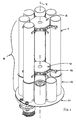
- the extraction device 1 is shown in Fig. 1 partially in order to facilitate understanding of the characteristics main features of the invention. It includes a system storage or carousel 10 in capsules arranged with so as to gather several series of capsules housed in removable refill elements 11. The capsules are thus stacked freely in the elements of refill or cartridges 11. Refill elements may take positions in a chosen order, on tube-supports 12 forming the base of the carousel. Support tubes we form tubes of the same configuration as the recharging elements so that these adapt in alignment to feed them in capsules. The length of the support tubes 12 depends on the buffer stock deemed necessary to provide service in the event of removal of the removable cartridges 11 during their replacement. The support tubes are through so to let the capsules pass from top to bottom.
- Support tubes are interconnected to form a whole rigid, easily rotatable without undergoing notable deformation.
- the cartridges 11 are mounted in orbit on a central assembly formed by frills 13, 14 vertically spaced to which means are attached removable connection 15 intended to retain the cartridges.
- connection means can be, as shown, pliers or any other equivalent means.
- the handwheels 13, 14 are mounted integrally in rotation on a central shaft (not shown) so that be able to drive the entire carousel 10 in rotation.
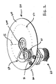
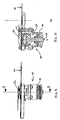
- Fig. 2 shows the means of unloading in capsules and the associated means of extraction.
- the unloading means comprise a support plate 20 fixed to the frame of the device.
- the support plate 20 is crossed by a central hole 200 allowing the passage of the system shaft storage (not shown).
- the system storage system 10 is therefore made mobile in rotation by relative to the support plate 20 which is fixed.
- the support plate 20 has an upper surface 210 forming a support and retention means for the capsules arranged in the support tubes 12; which are movable at sliding around the support plate 20.
- the support plate 20 comprises a passage 21 arranged eccentrically to the support plate but located in the circular path 22, shown in dotted lines, of the displacement of the tube-supports 12.
- the passage 21 has an opening for section corresponding to the opening section of the support tubes. So when a support tube is immobilized in alignment with the passage 21 of the support plate, the lowest capsule in the stack of the support tube selected is brought next to passage 21.
- a set shutter 30 having the function of controlling the lowering of the capsule located in the passage.
- the shutter assembly forms a base 31 of form substantially triangular contiguous to the support plate 20 and movable relative thereto angularly in two extreme positions; Moon corresponding to the closure of the passage, the other corresponding to the opening of the passage.
- Base 31 is thus displaceable around the central axis I and controlled by gear type means 33 (drive means not shown).
- the base is guided by means of guide 34 of the slots type as shown in order to fine-tune the movement of the base 31 between its two positions.
- the base 31 includes an opening 32 of section substantially equivalent to that of the passage.
- the opening 32 is located so as to move in the trajectory 22 of movement of the support tubes located on the opposite side of the backing plate.
- the base includes an extraction shower 35 of circular shape and arranged in the path 22 also at a distance from the opening 32.
- the shower extraction 35 comprises on its surface means for drilling 36 and means for supplying hot water (not shown).
- the drilling means 36 can be points, blades or any other equivalent means.
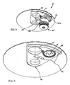
- a lower subset 40 is mounted integrally on the support plate 20.
- the sub-assembly 40 forms the part of reception of the capsule during loading. So the base 31 of the shutter system is movable by compared to this subset 40 along the means of guide 34 by means of fixing rods 41a, 41b making the sub-assembly 40 secured to the support plate.
- a separating element 37 is provided on the carousel side on the support plate whose the function is to separate the capsule located opposite the passage 21 at the time passage 21 is rendered coinciding with the opening 32 of the closure means.
- the separating element is coupled in movement with the base 31 so as to move from concert on the side opposite opening 32 of the base.
- the sealing element is, for example, a piece of inverted L shape with a partition wall substantially parallel to the height support plate by relative to the support plate such that the wall is suitable for to be inserted between the first capsule in the series selected and the second capsule in the series at when the shutter moves in the opening position for lowering the first capsule.
- the receiving sub-assembly 40 of the system will now be described with reference to Fig. 5 and 6.
- the capsules are identified under the common reference 5 and individually by references 50, 51, 52, 53.
- the reception sub-assembly includes an external base 42 fixed relative to the fastening means 41a, 41b, a fixed seat 43 extending the base having the function of receiving the capsule in adequate position.
- the seat thus has edges serving as a support for the edges 53 of the capsule.
- the seat On the side corresponding to the direction of movement of the base of the shutter system 31 to bring the passage in opening, the seat has a clearance 430. This clearance is provided for expelling the capsule after use outside the headquarters. Eviction is carried out by a means of expulsion 37 located under the base 31.
- On the side opposite the release is a slot 431 allowing the passage of the expulsion means 37 when returning to position of the extraction system.
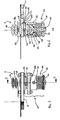
- a mobile chamber 44 having a distribution plate 45 having the purpose to open the capsule to release the liquid extract.
- the distribution plate has for that sharp reliefs capable of perforating the capsule under the effect of sufficient water pressure in the capsule.
- the chamber 44 can be moved in translation in the bore of the base 42.
- Displacement means 60 are provided to control the movement of the room in the base. These means include a piston assembly formed by the chamber 44 itself, the base 42, the channel flow 46, an internal pressurization chamber 47, seals 48, 49 for sealing the chamber 47, and a pressure fluid inlet 49. Ces. means are associated with elastic return means comprising a return spring 70 located between the base 42 and a support 71 allowing the return of the chamber 44 in open position.
- the carousel 10 is to rotate either manually either by an electric motor located under the device.
- the carousel is immobilized when the tube holder containing the desired capsule is found in coincidence in the passage 21 of the support plate 20.
- the selection of the capsule can be done according to different automatic modes.
- cartridges 11 may carry a means of identification such as a barcode readable by a reader located in the device.
- the barcode gives information on the type of capsule contained in the cartridge.
- the device After selecting the desired cartridge, the device is in the position illustrated in FIG. 2, with a capsule 51 in position in passage 21.
- the passage is closed by the closure means 30, the base 31 in the closed position; that is to say with the shower 35 above the receiving part 40 of the extraction system.
- the descent of the capsule 51 is then controlled by displacement in rotation of the means shutter 30 so as to make the passage coinciding 21 of the support plate with the opening 32 of the base shutter 31 as shown in FIG. 6.
- the capsule 50 extracted during the preceding cycle extraction is expelled by the expulsion means 37 at across clearance 430.
- the means of expulsion may be a blade or pusher capable of pushing the capsule 50 out of the seat and, on the contrary, flexible in the opposite direction so to be able to fold in contact with the capsule newly engaged in headquarters.
- the blade is positioned relative to the opening 32 so that expel the used capsule 50 before the descent of the new 51.
- the separation means 37 are moves together with the base 31 of the sealing means to be inserted between the descending capsule 51 and the second capsule 52 in the series. This can therefore be retained in place in the tube holder.
- the sealing means 30 is controlled for a return to position as shown in the Fig. 7 and 8.
- the descent-expulsion then return cycle in position can be very fast; about 1/2 second to 1 second and 1/2 approximately.
- the shower 35 provided in the base is positioned in alignment with the receiving part 40 of the extraction system. Return to position also the effect of lowering the capsule 52 in contact with the support plate 20 due to the withdrawal of the means of separation.
- the next step is to close the system extraction on the capsule to be extracted 51.
- the pressure chamber 47 is pressurized by injection of fluid through the opening 49; which moves the movable chamber 44 upwards until establishing a sufficient tightness of the cavity formed with the assembly lower and the shower 35.
- the capsule may have edges that are pinched when closed so that keep the capsule in place when closing.
- the extraction system is closed, the capsule is pierced by the points of the shower under the effect of the compression during closing. Water at temperature sufficient to carry out the extraction can then be introduced into the capsule through the shower 35.
- the pressure inside the capsule increases as as the volume of water introduced increases to get the rupture of the underside of the capsule at contact of the raised elements of the plate distribution 45.
- the liquid extract can then leave the capsule and flow through gravity through the flow channel 46.
- a container such that a cup is placed under the channel 46 so as to receive the liquid.
- a new load-expulsion cycle can then to start.
Description
La présente invention se rapporte au domaine de la préparation des boissons utilisant le principe d'extraction d'une substance contenue dans un élément de recharge, dit "capsule", par traversée d'un flux d'eau sous pression. L'invention se rapporte plus particulièrement à un dispositif d'extraction comprenant un système d'alimentation et de chargement en capsules.The present invention relates to the field of preparation of drinks using the principle extraction of a substance contained in an element of refill, called "capsule", by crossing a stream of water under pressure. The invention relates more particularly to an extraction device comprising a system of feeding and loading in capsules.
Il est connu de préparer des boissons telles que du café à partir de capsules contenant une dose prédéterminée de café torréfié moulu. Les capsules présentent l'avantage de faciliter les opérations de préparation de la boisson, d'assurer une préparation relativement propre sans déchet de marc visible, et de contrôler le dosage et la qualité du produit préparé.It is known to prepare drinks such as coffee from capsules containing a predetermined dose of ground roasted coffee. The capsules have the advantage to facilitate the operations for preparing the drink, ensure relatively clean preparation without waste of visible grounds, and to control the dosage and the quality of the prepared product.
Le principe d'extraction d'une capsule consiste à (i) enfermer la capsule dans une enceinte résistante à la pression, (ii) percer l'une des faces de la capsule généralement au moyen de pointe(s) ou lame(s) située(s) dans une partie comprenant une arrivée d'eau appelée communément "douche", (iii) introduire une quantité d'eau chaude dans la capsule de façon à créer un environnement sous pression à l'intérieur de l'élément pour produire l'extrait liquide de café puis, (iv) libérer l'extrait liquide de café au travers de la face opposée de la capsule qui, au contact de parties saillantes, s'ouvre sous l'effet de la pression interne créée dans la capsule.The principle of extracting a capsule consists of (i) enclose the capsule in an enclosure resistant to pressure, (ii) pierce one of the faces of the capsule usually by means of point (s) or blade (s) located (s) in a part including a water supply called commonly "shower", (iii) introduce a quantity of water hot in the capsule so as to create an environment under pressure inside the element to produce the liquid extract of coffee then, (iv) release the extract coffee liquid through the opposite side of the capsule which, in contact with protruding parts, opens under the effect of the internal pressure created in the capsule.
Dans la plupart des dispositifs d'extraction du commerce, le chargement des capsules se fait de façon manuelle et individuelle dans le porte-capsule d'extraction ; en général, partie correspondant à la base d'où s'écoule ensuite l'extrait liquide. Le porte-capsule peut se présenter sous différentes formes ; comme sous la forme d'une cuillère à engagement par baïllonnette du type de celles des machines expresso traditionnelles. Il existe aussi des systèmes de chargement en capsules du type à tiroir mobile susceptibles d'amener la capsule dans un mouvement pour chargement simplifié, linéaire horizontal ou autre, dans le système d'extraction. Un tel système est décrit dans la demande co-pendante européenne numéro 00110102.1 appartenant au déposant.In most commercial extraction devices, the capsules are loaded manually and individual in the extraction capsule holder; in general, part corresponding to the base from which flows then the liquid extract. The capsule holder can be present in different forms; as in the form a bayonet-type engagement spoon of the type of those of traditional espresso machines. It exists also loading systems in capsule type movable drawer capable of bringing the capsule into a movement for simplified loading, horizontal linear or whatever, in the extraction system. Such a system is described in European co-pending application number 00110102.1 belonging to the depositor.
Il existe cependant un besoin pour assurer une alimentation en capsules à partir d'une réserve de capsules ne nécessitant pas la manipulation directe avec la capsule mais au contraire, favorisant la disposition de manière plus automatisée des capsules dans le système d'extraction. Il existe aussi un besoin de mettre à la disposition des réserves de capsules de nature identique ou au contraire, différente, tout en offrant une grande facilité de chargement. De tels systèmes ont été décrits dans plusieurs publications déjà. Par exemple, la demande de brevet suisse No. 471 570 se rapporte aux machines automatiques à café comprenant un mécanisme de chauffage et de dosage d'eau, un mécanisme d'emmagasinage de cartouches de charge contenant de la poudre à café coopérant avec un mécanisme recevant et transportant les cartouches pour les placer devant une bouche de décharge d'eau chaude et pour faire sortir les cartouches après infusion ; tous ces mécanismes étant actionnés par des éléments moteurs synchronisés. Un tel dispositif est cependant très compliqué et prend une place considérable en raison du transport de la capsule entre son point d'emmagasinage et son point d'infusion.There is however a need to ensure a feeding capsules from a reserve of capsules not requiring direct handling with the capsule but on the contrary, favoring the arrangement more automated capsules in the system extraction. There is also a need to update provision of capsules of identical nature or on the contrary, different, while offering great easy loading. Such systems have been described in several publications already. For example, demand Swiss Patent No. 471,570 relates to machines automatic coffee machines including a heating mechanism and water dosing, a storage mechanism for charge cartridges containing coffee powder cooperating with a mechanism receiving and transporting cartridges to place them in front of a discharge mouth hot water and to remove the cartridges after infusion; all these mechanisms being actuated by synchronized motor elements. Such a device is however very complicated and takes up considerable space due to the transport of the capsule between its point and its infusion point.
La demande de brevet européenne No. 1046366 se rapporte à un dispositif pour l'alimentation de portions de café moulu dans une unité d'extraction ayant un magasin permettant d'accommoder une pluralité de portions de café et des moyens de déchargement des portions individuelles dans le dispositif d'alimentation. Le système de libération des capsules est relativement complexe et met en oeuvre plusieurs paires de gâchettes actionnables par des paires d'éléments d'actionnement eux-mêmes commandés par un électro-aimant. Chaque série ou tube de portions de café possède ses propres éléments de libération rendant le système relativement compliqué, peu rationnel et coûteux. D'autre part, le système demande une grande précision et une synchronisation parfaite du mouvement des éléments de libération qui doivent agir en même temps pour éviter tout coincement des portions de café dans le système. Au fur et à mesure des répétitions et de l'usure des pièces, un tel système peut s'avérer peu fiable et sujet à des défaillances plus ou moins sérieuses. Un autre inconvénient provient de ce que la chambre d'extraction recevant la portion doit pivoter sur le côté pour s'aligner dans la direction du support d'extraction puis s'élever pour rejoindre ledit support dans un mouvement linéaire. La combinaison répétée de mouvements complexes selon plusieurs axes est susceptible d'affecter la précision du système, favorise l'usure prématurée des pièces mécaniques et ainsi diminue la fiabilité ainsi que la durée de vie du dispositif. Un autre inconvénient provient de ce que l'extraction se fait de bas-en-haut, avec sortie du liquide extrait par le dessus du support d'extraction ; ce qui fait que l'on doit prévoir un tube d'amenée vers l'endroit de remplissage de la tasse. Une telle configuration pose des problèmes de vidange du liquide et aussi d'encombrement.European patent application No. 1046366 relates to a device for feeding portions of coffee ground in an extraction unit having a store to accommodate a plurality of portions of coffee and means for unloading the individual portions in the feeder. The system of releasing capsules is relatively complex and puts using several pairs of triggers that can be activated by pairs of actuators themselves controlled by an electromagnet. Each set or tube of portions of coffee has its own release elements making the system relatively complicated, not very rational and expensive. On the other hand, the system requires great precision and perfect synchronization of movement elements of liberation which must act at the same time to avoid jamming the coffee portions in the system. As repetitions and wear and tear parts, such a system can be unreliable and subject to more or less serious failures. A other drawback is that the room of extraction receiving the portion must pivot on the side to align in the direction of the extraction support then rise to join said support in a linear movement. The repeated combination of movements complex along several axes is likely to affect the precision of the system, promotes premature wear of mechanical parts and thus decreases reliability as well as the service life of the device. Another downside comes from the fact that the extraction is done from bottom-up, with outlet of the extracted liquid from above the support extraction; which means that we must provide a tube to the place where the cup is filled. A such configuration poses problems emptying the liquid and also bulk.
L'un des buts principaux de l'invention est donc de proposer un dispositif d'alimentation et de chargement associé à un système d'extraction de capsules qui soit plus simple, moins encombrant et d'utilisation plus fiable et sans problème d'écoulement et de vidange du liquide extrait.One of the main aims of the invention is therefore to offer a feeding and charging device associated with a capsule extraction system which is simpler, less bulky and more user-friendly reliable and without problem of flow and emptying of the liquid extracted.
Ce but est atteint avec un dispositif d'alimentation en capsules selon la revendication indépendante 1.This goal is achieved with a device for supplying capsules according to independent claim 1.
Une telle configuration participe donc à une alimentation plus directe, plus rapide et vise à limiter les interactions mécaniques pouvant engendrer une usure précoce et réduire la durée de vie du dispositif.Such a configuration therefore participates in a supply more direct, faster and aims to limit mechanical interactions which can cause wear early and reduce the lifespan of the device.
Selon un mode de réalisation avantageux, les moyens
de chargement comprennent : un moyen de support sur
lequel le moyen d'emmagasinage est déplaçable en rotation
comprenant un passage arrangé pour permettre la descente
d'une capsule dans la partie de réception du système
d'extraction selon une configuration d'alignement d'une
série par rapport au passage et,
un moyen d'obturation mobile par rapport audit
passage entre une position dans laquelle le passage est
obturé par le moyen d'obturation de façon à retenir la
capsule en regard du passage dans le moyen d'emmagasinage
et une position dans laquelle le passage est ouvert pour
autoriser la descente de la capsule dans la partie de
réception du système d'extraction.According to an advantageous embodiment, the loading means comprise: a support means on which the storage means is movable in rotation comprising a passage arranged to allow the descent of a capsule in the receiving part of the extraction system according to a configuration of alignment of a series with respect to the passage and,
shutter means movable relative to said passage between a position in which the passage is closed by the shutter means so as to retain the capsule facing the passage in the storage means and a position in which the passage is open to authorize the descent of the capsule into the receiving part of the extraction system.
Ainsi, une telle configuration a pour avantage de mettre en oeuvre pour le chargement en capsules un nombre réduit de pièces qui sont communes à toutes les séries de capsules ; à savoir le passage d'un moyen de support et un moyen d'obturation à deux positions communs tels que définis. Une telle configuration peut aussi permettre une sélection rapide de la capsule dans la série désirée par le passage puis par une libération de la capsule grâce au moyen à deux positions ; ceci, de manière fiable et rapide.Thus, such a configuration has the advantage of implement for loading capsules a number reduced parts which are common to all series of capsules; namely the passage of a support means and a shutter means with two common positions such as defined. Such a configuration can also allow a quick selection of the capsule in the series desired by the passage then by a release of the capsule thanks to the medium with two positions; this reliably and fast.
Selon un mode préféré, le moyen d'obturation comprend une partie complémentaire du système d'extraction qui lorsque le moyen se trouve dans la position d'obturation du passage se trouve dans l'alignement de la partie de réception du système d'extraction. En d'autre termes, l'obturation du passage après le chargement de la capsule a pour effet de rassembler les parties d'assemblage du système d'extraction dans un même alignement ; ce qui participe aussi à la réduction de la complexité du système en limitant le nombre de pièces et, par conséquent, des moyens d'entraínement (par ex. moteurs) nécessaires pour effectuer les fonctions de chargement et de positionnement du système d'extraction.According to a preferred mode, the closure means comprises a complementary part of the extraction system which when the medium is in the closed position of the passage is in alignment with the part of reception of the extraction system. In other words, closing the passage after loading the capsule has the effect of bringing together the assembly parts of the extraction system in the same alignment; what also contributes to reducing the complexity of the system by limiting the number of parts and, by therefore, means of drive (eg motors) necessary to perform the loading functions and positioning of the extraction system.
Plus particulièrement, la partie complémentaire du système d'extraction est une douche munie de moyen(s) pour l'introduction d'eau dans la capsule. On entend par "douche", la partie du système d'extraction ayant pour fonction de réaliser l'ouverture de la capsule pour l'alimenter en eau. L'invention propose donc que cette partie soit associée au moyen d'obturation mobile de façon à coordonner son déplacement à celui du moyen d'obturation lors du positionnement en fermeture du système d'extraction, de façon à simplifier le dispositif et réduire le temps de chargement par rapport à l'art existant.More specifically, the complementary part of the extraction system is a shower with means (s) for the introduction of water into the capsule. We hear by "shower", the part of the extraction system having for function of opening the capsule for supply it with water. The invention therefore proposes that this part is associated with the movable obturation of so as to coordinate its movement with that of the medium shutter during the closing positioning of the extraction system, so as to simplify the device and reduce loading time compared to art existing.
Selon un autre aspect de l'invention, la partie de réception du système d'extraction comprend un logement mobile pour loger la capsule et des moyens de déplacement permettant le déplacement en fermeture du logement contre la douche dans la direction d'alignement des deux parties pour permettre l'extraction. Autrement dit la fermeture du système d'extraction est obtenue par un mouvement relatif de translation ; donc moins complexe que les mouvements combinés rotation-translation de l'état de l'art, plus particulièrement de la demande EP 1046366. On obtient donc un assemblage plus rapide, une plus grande précision, moins d'usure dans le temps, et donc une durée de vie allongée du dispositif.According to another aspect of the invention, the part of receiving the extraction system includes a housing mobile for housing the capsule and displacement means allowing the closing movement of the housing against the shower in the direction of alignment of the two parts to allow extraction. In other words the closure of the extraction system is obtained by movement relative translation; therefore less complex than combined rotation-translation movements of the state of the art, more particularly of application EP 1046366. therefore achieves faster assembly, greater precision, less wear over time, and therefore a duration extended life of the device.
Dans un mode préféré, les moyens de déplacement comprennent un piston et une chambre de pression pressurisable par un fluide pour déplacer le piston et ainsi le logement dans la direction de la douche et un élément de rappel élastique permettant le retour en position d'ouverture du logement par retrait du piston. Un tel système est d'utilisation particulièrement fiable et produit une fermeture sécurisée et résistante à la pression. Toutefois, d'autres systèmes de fermeture peuvent aussi être envisagés comme par action mécanique du type à déplacement de la partie d'extraction mobile le long d'une tige filetée avec entraínement par moteur électrique, par exemple, ou tout autre moyen équivalent.In a preferred mode, the means of displacement include a piston and a pressure chamber pressurizable by a fluid to move the piston and well housing in the direction of the shower and a elastic return element allowing the return in position of opening of the housing by withdrawal of the piston. Such a system is particularly reliable to use and produces a secure and weather resistant closure pressure. However, other closure systems can also be considered as mechanical action of the displacement type of the movable extraction part the along a threaded rod with motor drive electric, for example, or any other equivalent means.
Selon un autre aspect de l'invention, les moyens de déchargement d'une capsule individuelle dans la partie de réception du système d'extraction comprennent par ailleurs un élément de séparation coordonné au mouvement de l'élément d'obturation de manière à s'introduire entre la première capsule dans la série positionnée en regard du passage et la seconde capsule dans la série au moment où l'élément d'obturation se déplace dans la position d'ouverture pour la descente de ladite première capsule. Une telle configuration participe aussi à la simplification du dispositif en évitant le recours à un élément indépendamment commandé.According to another aspect of the invention, the means of unloading of an individual capsule in the part of receipt of the extraction system include by elsewhere a separating element coordinated with the movement of the closure element so as to be inserted between the first capsule in the series positioned opposite of the passage and the second capsule in the series at the time where the shutter member moves to the position opening for the descent of said first capsule. Such a configuration also contributes to the simplification of the system by avoiding the use of a independently controlled element.
Selon une autre caractéristique avantageuse de l'invention, le moyen d'obturation comprend un moyen d'expulsion de la capsule qui expulse la capsule hors de la partie de réception du système d'extraction sous l'effet du déplacement de l'élément d'obturation en position d'ouverture de façon à libérer la partie de réception pour la descente d'une nouvelle capsule au travers du passage. Une telle configuration relève du même souci d'éviter le recours à un élément indépendamment commandé par des moyens de commandes supplémentaires mais tire parti du mouvement du moyen d'obturation lui-même.According to another advantageous characteristic of the invention, the sealing means comprises a means capsule expulsion which expels the capsule out of the receiving part of the extraction system under the effect of moving the shutter in open position so as to free the part of reception for the descent of a new capsule at across the passage. Such a configuration falls under the same concern to avoid recourse to an element independently controlled by control means but takes advantage of the medium movement shutter itself.
Ces caractéristiques et leurs avantages ainsi que
d'autres possibles pourront être mieux compris à la
lumière de la description qui suit et des dessins qui
suivent :
Le dispositif d'extraction 1 selon l'invention est
représenté à la Fig. 1 de manière partielle afin de
faciliter la compréhension des caractéristiques
principales de l'invention. Il comprend un système
d'emmagasinage ou carrousel 10 en capsules arrangé de
façon à rassembler plusieurs séries de capsules logées
dans des éléments de recharge amovibles 11. Les capsules
sont ainsi empilées de manière libre dans les éléments de
recharge ou cartouches 11. Les éléments de recharge
peuvent prendre position dans un ordre choisi, sur des
tube-supports 12 formant la base du carrousel. Les tube-supports
on la forme de tubes de même configuration que
les éléments de recharge de façon à ce que ceux-ci
s'adaptent en alignement pour les alimenter en capsules.
La longueur des tube-supports 12 est fonction du stock-tampon
jugé nécessaire pour assurer un service en cas de
retrait des cartouches amovibles 11 lors de leur
remplacement. Les tube-supports sont traversants de façon
à laisser passer les capsules de haut-en-bas. Les tube-supports
sont reliés entre eux pour former un ensemble
rigide facilement déplaçable en rotation sans subir de
déformation notable. Les cartouches 11 sont montées en
orbite sur un ensemble central formé de volants 13, 14
espacés verticalement auxquels sont rattachés des moyens
de connexion amovibles 15 destinés à retenir les
cartouches. Ces moyens de connexion peuvent être, comme
représentés, des pinces ou tout autre moyen équivalent.
Les volants 13, 14 sont montés de manière solidaire en
rotation sur un arbre central (non représenté) de façon à
pouvoir entraíner l'ensemble du carrousel 10 en rotation.The extraction device 1 according to the invention is
shown in Fig. 1 partially in order to
facilitate understanding of the characteristics
main features of the invention. It includes a system
storage or
La Fig. 2 montre les moyens de déchargement en
capsules et le moyen d'extraction qui y est associé.
Ainsi, les moyens de déchargement comprennent une
plaque-support 20 fixée au bâti du dispositif. La plaque-support
20 est traversée par un trou central 200
permettant le passage de l'arbre du système
d'emmagasinage (non-représenté). Le système
d'emmagasinage 10 est donc rendu mobile en rotation par
rapport à la plaque-support 20 qui est fixe. La plaque-support
20 présente une surface supérieure 210 formant un
moyen de support et de retenue aux capsules disposées
dans les tube-supports 12 ; lesquels sont déplaçables au
glissement autour de la plaque-support 20.Fig. 2 shows the means of unloading in
capsules and the associated means of extraction.
Thus, the unloading means comprise a
Selon l'invention, la plaque-support 20 comprend un
passage 21 disposé de manière excentrée par rapport à la
plaque-support mais situé dans la trajectoire circulaire
22, représentée en ligne pointillée, du déplacement des
tube-supports 12. Le passage 21 possède une ouverture de
section correspondante à la section d'ouverture des tube-supports.
Ainsi, lorsqu'un tube-support est immobilisé
dans l'alignement du passage 21 de la plaque-support, la
capsule la plus basse dans la pile du tube-support
sélectionné est amené en regard du passage 21.According to the invention, the
En dessous de la plaque-support se trouve un ensemble
d'obturation 30 ayant pour fonction de commander la
descente de la capsule se trouvant dans le passage.
L'ensemble d'obturation forme une base 31 de forme
sensiblement triangulaire contiguë par rapport à la
plaque-support 20 et déplaçable par rapport à celle-ci de
manière angulaire selon deux positions extrêmes; l'une
correspondant à l'obturation du passage, l'autre
correspondant à l'ouverture du passage. La base 31 est
ainsi dépaçable autour de l'axe central I et commandé par
des moyens du type à engrenage 33 (moyens d'entraínement
non-représentés). La base est guidée par des moyens de
guidage 34 du type fentes tels que représentés afin de
régler de manière précise le déplacement de la base 31
entre ses deux positions.Below the support plate is a
La base 31 comprend une ouverture 32 de section
sensiblement équivalente à celle du passage. L'ouverture
32 est localisée de manière à se déplacer dans la
trajectoire 22 de déplacement des tube-supports situés
sur le côté opposé de la plaque-support. De la même
manière, la base comprend une douche d'extraction 35 de
forme circulaire et disposée dans la trajectoire 22
également à distance de l'ouverture 32. La douche
d'extraction 35 comprend sur sa surface des moyens de
perçage 36 et des moyens d'alimentation en eau chaude
(non représentés). Les moyens de perçage 36 peuvent être
des pointes, lames ou tout autre moyen équivalent.The
Comme le montre la Fig. 3, un sous-ensemble inférieur
d'extraction 40 est monté de manière solidaire sur la
plaque-support 20. Le sous-ensemble 40 forme la partie de
réception de la capsule lors du chargement. Ainsi, la
base 31 du système d'obturation est déplaçable par
rapport à ce sous-ensemble 40 le long des moyens de
guidage 34 grâce à des tiges de fixation 41a, 41b rendant
le sous-ensemble 40 solidaire de la plaque-support.As shown in Fig. 3, a
De retour sur la Fig. 2, un élément de séparation 37
est prévu du côté du carrousel sur la plaque-support dont
la fonction est de séparer la capsule située en regard du
passage 21 au moment où le passage 21 est rendu
coïncidant avec l'ouverture 32 du moyen d'obturation.
Pour cela, l'élément de séparation est couplé en
mouvement avec la base 31 de façon à se déplacer de
concert du côté opposé à l'ouverture 32 de la base.
L'élément d'obturation est, par exemple, une pièce en
forme de L renversé présentant une paroi de séparation
sensiblement parallèle à la plaque support de hauteur par
rapport à la plaque-support telle que la paroi est apte à
s'insérer entre la première capsule de la série
sélectionnée et la seconde capsule dans la série au
moment où l'élément d'obturation se déplace dans la
position d'ouverture pour la descente de la première
capsule.Back in Fig. 2, a separating
Le sous-ensemble de réception 40 du système
d'extraction va maintenant être décrit en référence aux
Fig. 5 et 6. Les capsules sont identifiées sous la
référence commune 5 et individuellement par les
références 50, 51, 52, 53. Le sous-ensemble de réception
comprend une embase externe 42 fixe par rapport aux
moyens de fixation 41a,41b, un siège 43 fixe prolongeant
l'embase ayant pour fonction de recevoir la capsule en
position adéquate. Le siège possède ainsi des bords
servant d'appui aux bords 53 de la capsule. Du côté
correspondant au sens de déplacement de la base du
système d'obturation 31 pour amener le passage en
ouverture, le siège présente un dégagement 430. Ce
dégagement est prévu pour l'expulsion de la capsule après
usage hors du siège. L'expulsion est effectuée par un
moyen d'expulsion 37 localisé sous la base 31. Du côté
opposé au dégagement se trouve une fente 431 permettant
le passage du moyen d'expulsion 37 lors du retour en
position du système d'extraction.The receiving
En dessous du siège 43 se trouve une chambre mobile
44 possédant une plaque de répartition 45 ayant pour but
de réaliser l'ouverture de la capsule pour libérer
l'extrait liquide. La plaque de répartition possède pour
cela des reliefs aiguisés aptes à perforer la capsule
sous l'effet d'une pression d'eau suffisante dans la
capsule. La chambre 44 est déplaçable en translation dans
l'alésage de l'embase 42.Below
La chambre se prolonge vers le bas par un canal
d'écoulement 46 permettant la sortie par gravité du
liquide d'extraction directement dans le récipient (non
représenté). Des moyens de déplacement 60 sont prévus
pour commander le déplacement de la chambre dans
l'embase. Ces moyens comprennent un ensemble piston formé
par la chambre 44 elle-même, l'embase 42, le canal
d'écoulement 46, une chambre de pressurisation interne
47, des joints 48, 49 pour étanchéifier la chambre 47, et
une entrée de fluide de pression 49. Ces. moyens sont
associés à des moyens de rappel élastique comprenant un
ressort de rappel 70 localisés entre l'embase 42 et un
appui 71 permettant le retour de la chambre 44 en
position d'ouverture. The chamber extends downwards through a
Le principe de fonctionnement du dispositif selon l'invention va maintenant être décrit plus en détail en rapport avec les figures.The operating principle of the device according to the invention will now be described in more detail in relationship with the figures.
Dans un premier temps, après le choix par
l'utilisateur de la capsule dans la série ou cartouche
désirée, le carrousel 10 est entraíner en rotation soit
manuellement soit par un moteur électrique situé sous le
dispositif. Le carrousel est immobilisé lorsque le porte-tube
contenant la capsule désirée se trouve en
coïncidence dans le passage 21 de la plaque-support 20.
La sélection de la capsule peut se faire selon différents
modes automatiques. Par exemple, les cartouches 11
peuvent porter un moyen d'identification tel qu'un code-barre
lisible par un lecteur situé dans le dispositif. Le
code-barre donne des indications sur le type de capsule
contenu dans la cartouche. Ces indications sont lues par
le lecteur et traitées par un système de contrôle qui
commande le moteur du carrousel. Ainsi, la position
relative de la cartouche est sans influence sur le choix
et la sélection de la capsule.At first, after the choice by
capsule user in series or cartridge
desired, the
Après sélection de la cartouche désirée, le
dispositif se trouve dans la position illustrée à la Fig.
2, avec une capsule 51 en position dans le passage 21. Le
passage est obturé par le moyen d'obturation 30 dont la
base 31 en position de fermeture ; c'est à dire avec la
douche 35 au-dessus de la partie de réception 40 du
système d'extraction. La descente de la capsule 51 est
alors commandée par déplacement en rotation du moyen
d'obturation 30 de façon à rendre coïncidant le passage
21 de la plaque-support avec l'ouverture 32 de la base
d'obturation 31 comme le montre la Fig. 6. Au même
moment, la capsule 50 extraite lors du cycle précédant
d'extraction est expulsée par le moyen d'expulsion 37 au
travers du dégagement 430. Le moyen d'expulsion peut être
une lame ou poussoir apte à pousser la capsule 50 hors du
siège et, au contraire, flexible dans le sens opposé afin
de pouvoir se replier au contact de la capsule
nouvellement engagée dans le siège. La lame est
positionnée par rapport à l'ouverture 32 de telle sorte à
expulser la capsule usagée 50 avant la descente de la
nouvelle 51. Au moment de la descente de la nouvelle
capsule 51 dans le siège 43, le moyen de séparation 37 se
déplace de concert avec la base 31 du moyen d'obturation
pour s'insérer entre la capsule descendante 51 et la
second capsule 52 dans la série. Celle-ci peut ainsi être
retenue en place dans le porte-tube.After selecting the desired cartridge, the
device is in the position illustrated in FIG.
2, with a
Après descente de la nouvelle capsule et expulsion de
la capsule usagée, le moyen d'obturation 30 est commandé
pour un retour en position telle que représenté aux la
Fig. 7 et 8. Le cycle de descente-expulsion puis retour
en position peut être très rapide ; de l'ordre d'1/2
seconde à 1 seconde et 1/2 environ. Dans la position de
chargement représentée, la douche 35 prévue dans la base
est positionnée en alignement de la partie de réception
40 du système d'extraction. Le retour en position a aussi
pour effet de faire descendre la capsule 52 au contact de
la plaque-support 20 en raison du retrait du moyen de
séparation.After lowering the new capsule and expelling
the used capsule, the sealing means 30 is controlled
for a return to position as shown in the
Fig. 7 and 8. The descent-expulsion then return cycle
in position can be very fast; about 1/2
second to 1 second and 1/2 approximately. In the position of
loading shown, the
L'étape suivant consiste à refermer le système
d'extraction sur la capsule à extraire 51. Pour cela, la
chambre de pression 47 est pressurisée par injection de
fluide au travers de l'ouverture 49; ce qui déplace la
chambre mobile 44 vers le haut jusqu'à établir une
étanchéité suffisante de la cavité formée avec l'ensemble
inférieur et la douche 35. La capsule peut présenter des
bords qui sont pincés lors de la fermeture de façon à
maintenir en bonne place la capsule lors de la fermeture.
Une fois fermé le système d'extraction, la capsule est
percée par les pointes de la douche sous l'effet de la
compression lors de la fermeture. De l'eau à température
suffisante pour réaliser l'extraction peut alors être
introduite dans la capsule au travers de la douche 35. La
pression à l'intérieur de la capsule augmente au fur et à
mesure que le volume d'eau introduit augmente jusqu'à
obtenir la rupture de la face inférieure de la capsule au
contact des éléments en relief de la plaque de
répartition 45. Comme le montre la Fig. 10, le liquide
extrait peut alors quitter la capsule et s'écouler par
gravité au travers du canal d'écoulement 46. Un récipient
tel qu'une tasse est disposé sous le canal 46 de façon à
recevoir le liquide.The next step is to close the system
extraction on the capsule to be extracted 51. For this, the
Un nouveau cycle de chargement-expulsion peut alors commencer.A new load-expulsion cycle can then to start.
L'invention a été décrite à titre d'exemple préférentiel en rapport avec un mode préférentiel. Cependant, il est entendu que l'invention peut comprendre de nombreuses variantes ou équivalents à la portée de l'homme de l'art.The invention has been described by way of example preferential in relation to a preferential mode. However, it is understood that the invention may include many variations or equivalents within the scope of one skilled in the art.
Claims (11)
- Device for supplying cartridges containing a substance to be extracted comprising a pressurized extraction system (1) for the preparation of a beverage and comprising a means of storage (10) comprising cartridges (5) arranged in several series, means (20,21,200,210,30) for individually discharging a cartridge through a passage (21) in a receiving part (40) of the extraction system arranged below the discharge means so as to enable the freed cartridge to descend directly into the receiving part (40), characterized in that the receiving part (40) is fixed in the alignment of the said passage (21) and includes means (44,45) for opening the cartridge capable of liberating the liquid extract and means for conducting (46) this extract.
- Supply device according to claim 1, characterized in that the discharge means comprise :a supporting means (20) on which the storage means (10) can be moved in rotation including the said passage (21) arranged so to enable a cartridge to descend into the receiving part of the extraction system according to a configuration where a series is aligned with respect to the passage (21) and,a sealing means (30) that is movable with respect to the said passage (21) between the position in which the passage is sealed by the sealing means (30) so as to hold the cartridge opposite the passage in the storage means (10) and a position in which the passage is open so as to permit the descent of the cartridge into the receiving part (40) of the extraction system.
- Device according to claim 2, characterized in that the sealing means (30) includes a complementary part of the extraction system which, when the means is situated in the position where the passage is sealed (21), is situated aligned with the receiving part of the extraction system.
- Device according to claim 3, characterized in that the complementary part of the extraction system is a shower (35) provided with means (36) for introducing water into the cartridge.
- Device according to claim 3 or 4, characterized in that the receiving part (40) of the extraction system includes a movable housing (44) for housing the cartridge and means of movement (60) permitting movement while closed of the housing against the shower (35) in the direction of alignment of the two parts (40, 30) in order to permit extraction.
- Device according to claim 5 characterized in that the means of movement (60) comprise a piston (44), a pressurizable pressure chamber (47) for moving the piston and therefore the housing in the direction of the shower (31) and an elastic return element (70) enabling the housing to return to the open position by retraction of the piston.
- Device according to any one of claims 2 to 6, characterized in that the movable sealing means (30) is mounted coaxially with respect to the supporting means (20) so that it can be moved along a portion of arc between two positions.
- Device according to any one of claims 2 to 7, characterized in that the means for discharging an individual cartridge into the receiving part of the extraction system additionally include a separating element coordinated to the movement of the sealing element so as to be introduced between the first cartridge in the series positioned opposite the passage and the second cartridge in the series at the moment when the sealing element (30) moves into the open position for the descent of the said first cartridge.
- Device according to any one of claims 2 to 8, characterized in that the sealing means (30) includes a means (37) for expelling the cartridge which expels the cartridge outside the receiving part of the extraction system under the effect of the movement of the sealing element into the open position so as to free the receiving part for the descent of a new cartridge through the passage.
- Device according to any one of the preceding claims characterized in that the means for opening the receiving part of the extraction system is a pressurised distribution plate (45) provided with raised portions for opening the cartridge and openings for the passage of the liquid extract.
- Device according to claim 10, characterized in that the conducting means of the receiving part of the system includes an outflow channel (46) situated below the pressurized distribution plate.
Priority Applications (23)
| Application Number | Priority Date | Filing Date | Title |
|---|---|---|---|
| PT01108382T PT1247481E (en) | 2001-04-03 | 2001-04-03 | EXTRACTION DEVICE WITH INTEGRATED CAPSULES CHARGING SYSTEM |
| DE60107199T DE60107199T2 (en) | 2001-04-03 | 2001-04-03 | Extraction device with integrated Kapselzuführeinrichtung |
| EP01108382A EP1247481B1 (en) | 2001-04-03 | 2001-04-03 | Extraction apparatus with integrated cartridge supply system |
| SI200130254T SI1247481T1 (en) | 2001-04-03 | 2001-04-03 | Extraction apparatus with integrated cartridge supply system |
| ES01108382T ES2231331T3 (en) | 2001-04-03 | 2001-04-03 | EXTRACTION DEVICE WITH INTEGRATED CAPSULES LOAD SYSTEM. |
| AT01108382T ATE282353T1 (en) | 2001-04-03 | 2001-04-03 | EXTRACTION DEVICE WITH INTEGRATED CAPSULE FEEDING DEVICE |
| DK01108382T DK1247481T3 (en) | 2001-04-03 | 2001-04-03 | Extraction device with integrated capsule insertion system |
| BR0208557-7A BR0208557A (en) | 2001-04-03 | 2002-03-26 | Extraction device with integrated capsule loading system |
| AU2002344146A AU2002344146B2 (en) | 2001-04-03 | 2002-03-26 | Extracting device with integrated capsule loading system |
| MXPA03009055A MXPA03009055A (en) | 2001-04-03 | 2002-03-26 | Extracting device with integrated capsule loading system. |
| PL02363759A PL363759A1 (en) | 2001-04-03 | 2002-03-26 | Extracting device with integrated capsule loading system |
| PCT/EP2002/003632 WO2002096253A1 (en) | 2001-04-03 | 2002-03-26 | Extracting device with integrated capsule loading system |
| JP2002592774A JP3899318B2 (en) | 2001-04-03 | 2002-03-26 | Capsule loading system built-in extraction device |
| RU2003132057/12A RU2003132057A (en) | 2001-04-03 | 2002-03-26 | EXTRACTION DEVICE WITH AN INTEGRATED CAPSULE LOADING SYSTEM |
| CN02807765.2A CN100536732C (en) | 2001-04-03 | 2002-03-26 | Extracting device with integrated capsule loading system |
| CA2441475A CA2441475C (en) | 2001-04-03 | 2002-03-26 | Extracting device with integrated capsule loading system |
| IL15786902A IL157869A0 (en) | 2001-04-03 | 2002-03-26 | Extracting device with integrated capsule loading system |
| ARP020101176A AR038773A1 (en) | 2001-04-03 | 2002-04-02 | APPARATUS FOR THE PREPARATION OF DRINKS BY EXTRACTION UNDER PRESSURE OF SUBSTANCES CONTAINED IN CAPSULES |
| TW091106633A TW561035B (en) | 2001-04-03 | 2002-04-02 | Device for feeding capsules containing a substance to be extracted in an extraction system under pressure for the preparation of a drink |
| IL157869A IL157869A (en) | 2001-04-03 | 2003-09-11 | Extracting device with integrated capsule loading system |
| NO20034416A NO324190B1 (en) | 2001-04-03 | 2003-10-02 | Extraction device for feeding capsules |
| US10/676,001 US6941855B2 (en) | 2001-04-03 | 2003-10-02 | Extraction device with built-in capsule loading system |
| ZA200308494A ZA200308494B (en) | 2001-04-03 | 2003-10-30 | Extracting device with integrated capsule loading system. |
Applications Claiming Priority (1)
| Application Number | Priority Date | Filing Date | Title |
|---|---|---|---|
| EP01108382A EP1247481B1 (en) | 2001-04-03 | 2001-04-03 | Extraction apparatus with integrated cartridge supply system |
Publications (2)
| Publication Number | Publication Date |
|---|---|
| EP1247481A1 EP1247481A1 (en) | 2002-10-09 |
| EP1247481B1 true EP1247481B1 (en) | 2004-11-17 |
Family
ID=8177033
Family Applications (1)
| Application Number | Title | Priority Date | Filing Date |
|---|---|---|---|
| EP01108382A Expired - Lifetime EP1247481B1 (en) | 2001-04-03 | 2001-04-03 | Extraction apparatus with integrated cartridge supply system |
Country Status (22)
| Country | Link |
|---|---|
| US (1) | US6941855B2 (en) |
| EP (1) | EP1247481B1 (en) |
| JP (1) | JP3899318B2 (en) |
| CN (1) | CN100536732C (en) |
| AR (1) | AR038773A1 (en) |
| AT (1) | ATE282353T1 (en) |
| AU (1) | AU2002344146B2 (en) |
| BR (1) | BR0208557A (en) |
| CA (1) | CA2441475C (en) |
| DE (1) | DE60107199T2 (en) |
| DK (1) | DK1247481T3 (en) |
| ES (1) | ES2231331T3 (en) |
| IL (2) | IL157869A0 (en) |
| MX (1) | MXPA03009055A (en) |
| NO (1) | NO324190B1 (en) |
| PL (1) | PL363759A1 (en) |
| PT (1) | PT1247481E (en) |
| RU (1) | RU2003132057A (en) |
| SI (1) | SI1247481T1 (en) |
| TW (1) | TW561035B (en) |
| WO (1) | WO2002096253A1 (en) |
| ZA (1) | ZA200308494B (en) |
Families Citing this family (74)
| Publication number | Priority date | Publication date | Assignee | Title |
|---|---|---|---|---|
| ES2226531B1 (en) * | 2002-07-04 | 2006-05-16 | Francisco Navarro Alcantara | PROCEDURE, MACHINE AND PACK FOR THE PREPARATION AND EXPEDITION OF HOT AND COLD DRINKS. |
| ITPN20020090A1 (en) * | 2002-11-21 | 2004-05-22 | Necta Vending Solutions Spa | CAPSULE FEEDING APPARATUS FOR DISTRIBUTORS |
| US7640843B2 (en) | 2003-01-24 | 2010-01-05 | Kraft Foods R & D, Inc. | Cartridge and method for the preparation of beverages |
| US7607385B2 (en) * | 2003-01-24 | 2009-10-27 | Kraft Foods R & D, Inc. | Machine for the preparation of beverages |
| DE20302410U1 (en) | 2003-02-13 | 2004-06-24 | Nestec S.A. | Capsule magazine unit with capsule magazine unit receiving device, in particular an espresso machine |
| US20050082308A1 (en) * | 2003-10-16 | 2005-04-21 | Simson Anton K. | Machine for controlled dispensing of small articles |
| DE102004016194B4 (en) * | 2004-04-01 | 2013-05-29 | Leopold Kostal Gmbh & Co. Kg | Hot beverage facility |
| SI1748713T1 (en) | 2004-05-05 | 2008-06-30 | Nestec Sa | Capsule loading device for feeding a capsules dispensing machine |
| PT1744650E (en) * | 2004-05-05 | 2008-12-22 | Nestec Sa | Capsule-dispensing cabinet for supplying machines for the preparation of drinks or other food preparations |
| ITPN20050076A1 (en) * | 2005-10-20 | 2007-04-21 | C M A Spa | POD LOADER GROUP FOR INFUSION DRINKS OF VARIOUS KIND FOR COFFEE MACHINES |
| US10631558B2 (en) * | 2006-03-06 | 2020-04-28 | The Coca-Cola Company | Methods and apparatuses for making compositions comprising an acid and an acid degradable component and/or compositions comprising a plurality of selectable components |
| ITMI20061307A1 (en) | 2006-07-06 | 2008-01-07 | Perfect Steam Appliances Ltd | INFUSION GROUP FOR MACHINE FOR THE PREPARATION OF DRINKS |
| GB2447024A (en) | 2007-02-27 | 2008-09-03 | Kraft Foods R & D Inc | A dispensing machine for hot or cold drinks |
| ITMI20070571A1 (en) * | 2007-03-22 | 2008-09-23 | Ricerche E Sviluppo S A S | EQUIPMENT FOR THE PREPARATION AND DISTRIBUTION OF BEVERAGES FROM A POWDER CONTAINED IN CAPSULES |
| GB2449213B (en) | 2007-05-18 | 2011-06-29 | Kraft Foods R & D Inc | Improvements in or relating to beverage preparation machines and beverage cartridges |
| GB2462392B (en) | 2007-05-18 | 2010-08-18 | Kraft Foods R & D Inc | Beverage preparation machines and methods for operating beverage preparation machines |
| GB2449421B (en) | 2007-05-18 | 2009-09-09 | Kraft Foods R & D Inc | Improvements in or relating to beverage preparation machines |
| GB2449422B (en) | 2007-05-18 | 2009-09-16 | Kraft Foods R & D Inc | Improvements in or relating to beverage preparation machines |
| GB2463350B (en) | 2007-05-18 | 2010-07-28 | Kraft Foods R & D Inc | Improvements in or relating to beverage preparation machines |
| GB2454656A (en) | 2007-11-09 | 2009-05-20 | Kraft Foods R & D Inc | A beverage cartridge |
| US7987768B2 (en) * | 2008-03-27 | 2011-08-02 | The Coca-Cola Company | Brewing mechanism |
| CN102014708A (en) * | 2008-04-28 | 2011-04-13 | 塔塔全球饮料有限公司 | An assembly for automatic fresh brewing of hot beverage and dispensing thereof |
| US20110041701A1 (en) * | 2008-04-28 | 2011-02-24 | Ashim Chatterjee | Automatic pod conveyor and brewer assembly for fresh hot beverage |
| US20110308397A1 (en) * | 2008-07-21 | 2011-12-22 | Vital Products B.V. | Assembly, package and apparatus for preparing a beverage |
| EP2233051B1 (en) | 2009-03-27 | 2014-05-07 | Kraft Foods R & D, Inc. | Beverage concentrates |
| PT2475291E (en) * | 2009-09-09 | 2015-05-11 | Nestec Sa | Beverage machine in a network |
| JP6081198B2 (en) * | 2009-09-24 | 2017-02-15 | コーニンクラケ ダウ エグバート ビー.ブイ. | Beverage cartridge |
| EP2306417A1 (en) | 2009-09-25 | 2011-04-06 | F.A.S. International S.p.A. | Cartridge magazine |
| JP2013510680A (en) | 2009-11-12 | 2013-03-28 | ジェネレーション アイ.ディー.イー.エー.,エルエルシー. | Apparatus and method for preparing a liquid mixture |
| AU2010334941B2 (en) | 2009-12-21 | 2015-07-16 | Société des Produits Nestlé S.A. | Identification of beverage ingredient containing capsules |
| ES2588727T3 (en) | 2010-05-12 | 2016-11-04 | Nestec S.A. | Capsule, system and method to prepare a beverage by centrifugation |
| MX343926B (en) * | 2010-08-13 | 2016-11-29 | Douwe Egberts Bv | Device, system and method for preparing a beverage suitable for consumption from a capsule. |
| US9062912B2 (en) | 2010-10-29 | 2015-06-23 | Whirlpool Corporation | Multi-single serve beverage dispensing apparatus, method and system |
| USD694620S1 (en) | 2011-03-08 | 2013-12-03 | Kraft Foods R&D, Inc. | Beverage cartridge |
| GB2488799A (en) | 2011-03-08 | 2012-09-12 | Kraft Foods R & D Inc | Drinks Pod without Piercing of Outer Shell |
| SE535776C2 (en) * | 2011-03-10 | 2012-12-11 | Shahram Pourshakour | Device for storage and feeding of raw materials in the production of fruit and / or vegetable juices |
| GB2489409B (en) | 2011-03-23 | 2013-05-15 | Kraft Foods R & D Inc | A capsule and a system for, and a method of, preparing a beverage |
| WO2012131075A1 (en) * | 2011-03-31 | 2012-10-04 | Soitec | Methods for bonding semiconductor structures involving annealing processes, and bonded semiconductor structures formed using such methods |
| FR2976779B1 (en) * | 2011-06-24 | 2014-09-05 | Christian Ferrier | BEVERAGE INFUSION BEVERAGE PREPARATION DEVICE |
| ITMI20111476A1 (en) * | 2011-08-02 | 2013-02-03 | De Longhi Appliances Srl | SELECTIVE LOADER OF A COFFEE CAP IN AN INFUSOR OF A COFFEE MACHINE |
| DE102011053294A1 (en) * | 2011-09-06 | 2013-03-07 | Eugster/Frismag Ag | Method and device for producing a coffee preparation |
| JP2013186625A (en) * | 2012-03-07 | 2013-09-19 | Panasonic Corp | Powder raw material supply device |
| CN104185435B (en) * | 2012-03-26 | 2017-12-19 | 皇家飞利浦有限公司 | Equipment for orienting the capsule in beverage maker |
| USD697797S1 (en) | 2012-09-12 | 2014-01-21 | Kraft Foods R&D, Inc. | Beverage cartridge |
| DE102013202677A1 (en) | 2013-02-19 | 2014-08-21 | Eugster/Frismag Ag Elektrohaushaltgeräte | Magazine unit, brewing system and method for populating a brewing device with a portion capsule |
| US9907428B2 (en) | 2013-03-07 | 2018-03-06 | Nestec S. A. | Dispensing device with barrier properties |
| DE202013101550U1 (en) * | 2013-04-11 | 2013-06-10 | Sata Gmbh & Co. Kg | Dispenser and dispenser system for at least one component of a cup system, in particular a color cup system |
| PT107335B (en) * | 2013-12-02 | 2020-07-13 | Novadelta - Comércio E Indústria De Cafés, Lda. | SIMPLIFIED CONSTRUCTION EXTRACTION DEVICE AND BEVERAGE PREPARATION SYSTEM INCLUDING THIS DEVICE |
| US9439532B2 (en) * | 2014-03-11 | 2016-09-13 | Starbucks Corporation | Beverage production machines with multi-chambered basket units |
| DE102014213798A1 (en) * | 2014-07-16 | 2016-01-21 | BSH Hausgeräte GmbH | Household refrigerating appliance with a water dispenser unit having a receiving unit for inserting a flavor container |
| CA2962107C (en) | 2014-10-01 | 2023-05-09 | Kraft Foods Group Brands Llc | Coffee pod |
| CA2983872C (en) * | 2015-05-07 | 2023-06-20 | Smart Wave Technologies Corp. | Signal and detection system for pairing products |
| US10602874B2 (en) | 2015-06-16 | 2020-03-31 | Starbucks Corporation Dba Starbucks Coffee Company | Beverage preparation systems with brew chamber access mechanisms |
| US10342377B2 (en) | 2015-06-16 | 2019-07-09 | Starbucks Corporation | Beverage preparation systems with adaptable brew chambers |
| ITUB20153092A1 (en) * | 2015-08-12 | 2017-02-12 | Gironimo Gino Di | MACHINE TO PREPARE AND DELIVER HOT DRINKS |
| CN208791164U (en) * | 2015-11-23 | 2019-04-26 | Mb2杯子发展有限责任公司 | It is used to prepare the system and device of drink capsule |
| US20220361705A1 (en) * | 2015-11-23 | 2022-11-17 | Cupper, Llc | System, apparatus and method for preparing a beverage cartridge |
| US11745906B2 (en) * | 2015-11-23 | 2023-09-05 | Cupper Llc | System, apparatus, and method for preparing a beverage cartridge |
| ES2939370T3 (en) * | 2016-01-12 | 2023-04-21 | Freezio Ag | Dispensing system with cartridge holder |
| US20170119200A1 (en) * | 2016-01-19 | 2017-05-04 | Anthony David Bressi | Automated beverage and fragrance synthesizers |
| FR3048171B1 (en) * | 2016-02-25 | 2018-03-30 | Kuantom | APPARATUS FOR MAKING A BEVERAGE |
| CN106251490B (en) * | 2016-07-19 | 2019-05-24 | 卜鹏飞 | Fruit juice self-service sale device |
| RU2754461C1 (en) | 2016-11-09 | 2021-09-02 | Пепсико, Инк. | Devices, methods and systems for preparation of carbonated beverages |
| US10217310B2 (en) * | 2017-04-21 | 2019-02-26 | Noodle Time Holdings Limited | Vending machine |
| KR101837348B1 (en) * | 2017-07-24 | 2018-04-19 | 주식회사 해성엔지니어링 | Coffee vending machines |
| CN107424314A (en) * | 2017-08-10 | 2017-12-01 | 厦门未来营养生物科技有限公司 | A kind of personalized nutritional compensation process and equipment |
| CN107472920B (en) * | 2017-09-11 | 2023-09-01 | 张家港易智自动化装备有限公司 | Corner connector feeding device |
| ES2873938T3 (en) * | 2017-12-22 | 2021-11-04 | Nestle Sa | Interchangeable cartridge for beverage portion dispenser |
| ES2824508T3 (en) * | 2017-12-22 | 2021-05-12 | Nestle Sa | Portion dispenser for dispensing portioned beverage items |
| CN108742151B (en) * | 2018-06-05 | 2024-03-29 | 深圳市道中创新科技有限公司 | Powder-brewing capsule feeding structure and instant-brewing beverage vending machine |
| CN109091002B (en) * | 2018-07-17 | 2021-01-12 | 无锡鼎加弘思饮品科技有限公司 | Buckle formula ejection of compact structure based on coffee capsule |
| USD971671S1 (en) * | 2019-06-07 | 2022-12-06 | World Matcha Inc. | Liquid preparing device |
| EP4340684A1 (en) * | 2021-05-18 | 2024-03-27 | Universal Brand Group (Pty) Limited | Intelligent hot beverage maker |
| IT202100023834A1 (en) * | 2021-09-16 | 2023-03-16 | Se Ri Cos S R L | MULTIFUNCTION CAPSULE MACHINE FOR ESPRESSO COFFEE AND OTHER HOT DRINKS CAN BE CONTROLLED BOTH LOCALLY AND REMOTELY |
Family Cites Families (5)
| Publication number | Priority date | Publication date | Assignee | Title |
|---|---|---|---|---|
| US2243895A (en) * | 1938-09-21 | 1941-06-03 | William F Brown | Beverage machine |
| CA1280903C (en) * | 1987-05-30 | 1991-03-05 | Hirosato Takeuchi | Dispenser |
| DK0891734T3 (en) * | 1997-07-14 | 2001-01-29 | Nestle Sa | Apparatus for the manufacture of a beverage |
| IT1302461B1 (en) * | 1998-11-17 | 2000-09-05 | Antonio Adriani | COFFEE DISPENSING MACHINE, TEA AND OTHER SIMILAR PRODUCTS OBTAINED BY INFUSION. |
| DK1046366T3 (en) | 1999-04-23 | 2005-09-05 | Fianara Int Bv | Apparatus for supplying packaged portions of ground coffee in a cooking unit |
-
2001
- 2001-04-03 AT AT01108382T patent/ATE282353T1/en not_active IP Right Cessation
- 2001-04-03 SI SI200130254T patent/SI1247481T1/en unknown
- 2001-04-03 ES ES01108382T patent/ES2231331T3/en not_active Expired - Lifetime
- 2001-04-03 DE DE60107199T patent/DE60107199T2/en not_active Expired - Lifetime
- 2001-04-03 EP EP01108382A patent/EP1247481B1/en not_active Expired - Lifetime
- 2001-04-03 PT PT01108382T patent/PT1247481E/en unknown
- 2001-04-03 DK DK01108382T patent/DK1247481T3/en active
-
2002
- 2002-03-26 IL IL15786902A patent/IL157869A0/en active IP Right Grant
- 2002-03-26 RU RU2003132057/12A patent/RU2003132057A/en not_active Application Discontinuation
- 2002-03-26 BR BR0208557-7A patent/BR0208557A/en not_active Application Discontinuation
- 2002-03-26 AU AU2002344146A patent/AU2002344146B2/en not_active Ceased
- 2002-03-26 MX MXPA03009055A patent/MXPA03009055A/en active IP Right Grant
- 2002-03-26 CA CA2441475A patent/CA2441475C/en not_active Expired - Fee Related
- 2002-03-26 PL PL02363759A patent/PL363759A1/en not_active IP Right Cessation
- 2002-03-26 JP JP2002592774A patent/JP3899318B2/en not_active Expired - Fee Related
- 2002-03-26 CN CN02807765.2A patent/CN100536732C/en not_active Expired - Fee Related
- 2002-03-26 WO PCT/EP2002/003632 patent/WO2002096253A1/en active Application Filing
- 2002-04-02 TW TW091106633A patent/TW561035B/en active
- 2002-04-02 AR ARP020101176A patent/AR038773A1/en not_active Application Discontinuation
-
2003
- 2003-09-11 IL IL157869A patent/IL157869A/en not_active IP Right Cessation
- 2003-10-02 US US10/676,001 patent/US6941855B2/en not_active Expired - Lifetime
- 2003-10-02 NO NO20034416A patent/NO324190B1/en not_active IP Right Cessation
- 2003-10-30 ZA ZA200308494A patent/ZA200308494B/en unknown
Also Published As
| Publication number | Publication date |
|---|---|
| TW561035B (en) | 2003-11-11 |
| ES2231331T3 (en) | 2005-05-16 |
| AU2002344146B2 (en) | 2007-09-20 |
| NO20034416L (en) | 2003-11-19 |
| EP1247481A1 (en) | 2002-10-09 |
| AR038773A1 (en) | 2005-01-26 |
| MXPA03009055A (en) | 2004-02-12 |
| SI1247481T1 (en) | 2005-02-28 |
| IL157869A (en) | 2008-03-20 |
| DE60107199D1 (en) | 2004-12-23 |
| US6941855B2 (en) | 2005-09-13 |
| US20050000366A9 (en) | 2005-01-06 |
| IL157869A0 (en) | 2004-03-28 |
| JP3899318B2 (en) | 2007-03-28 |
| US20040129145A1 (en) | 2004-07-08 |
| JP2004526549A (en) | 2004-09-02 |
| DK1247481T3 (en) | 2005-02-14 |
| NO324190B1 (en) | 2007-09-03 |
| PT1247481E (en) | 2005-03-31 |
| ZA200308494B (en) | 2005-01-07 |
| NO20034416D0 (en) | 2003-10-02 |
| PL363759A1 (en) | 2004-11-29 |
| WO2002096253A1 (en) | 2002-12-05 |
| CA2441475C (en) | 2010-09-21 |
| RU2003132057A (en) | 2005-02-27 |
| CN100536732C (en) | 2009-09-09 |
| CN1499948A (en) | 2004-05-26 |
| DE60107199T2 (en) | 2005-11-03 |
| CA2441475A1 (en) | 2002-12-05 |
| ATE282353T1 (en) | 2004-12-15 |
| BR0208557A (en) | 2004-03-02 |
Similar Documents
| Publication | Publication Date | Title |
|---|---|---|
| EP1247481B1 (en) | Extraction apparatus with integrated cartridge supply system | |
| EP1310199B1 (en) | Device and method for selecting and extracting a cartridge for preparing a beverage | |
| EP1444932B1 (en) | Linear extraction unit for the preparation under pressure of a drink from a cartridge | |
| EP1757212B2 (en) | Device for extracting a capsule | |
| EP2083662B1 (en) | Assembly comprising an appliance and a disposable capsule for producing a brewed drink, and capsule for such an assembly | |
| EP0199953B1 (en) | Automat for making a beverage | |
| EP1778063B1 (en) | Unit for preparing at least one espresso coffee cup or other hot beverage from a prepackaged single so-called coffee pod | |
| EP0717603B1 (en) | Packaging of ground coffee of the predosed pastille type and espresso coffee machine using such packaging | |
| CA2888635A1 (en) | Device for preparing beverages by pod infusion having a pivoting cradle | |
| EP1146807B1 (en) | Coffee extracting device | |
| EP1480540A1 (en) | Device for producing beverage by infusion | |
| EP2020891A1 (en) | Machine for producing espresso-type coffee | |
| EP1900314B1 (en) | Machine for preparing an infusion equipped with a device for ejecting a dose of infused product | |
| EP1139832A1 (en) | Extraction chamber for an automatic machine preparing hot drinks | |
| EP3262994B1 (en) | Device for preparing beverage by brewing a powder contained in a capsule | |
| EP2139369A1 (en) | Apparatus for preparing and dispensing beverages from a powder contained in capsules | |
| WO2014206991A1 (en) | Device for preparing infused drinks, comprising an injection tube leading into the infusion chamber | |
| FR2886121A1 (en) | Pod ejector device for hot drink e.g. espresso coffee, preparing unit, has pusher with rod projecting outside lower part of tilting receiver plate so that part of rod thrusts against vertical contact surface of unit when plate is tilted | |
| EP1593326A1 (en) | Dispensing device for stacked articles | |
| WO2014206993A1 (en) | Device for preparing infused drinks, comprising a pivoting capsule support | |
| WO2012107867A2 (en) | Device for filling bags | |
| FR2905844A1 (en) | Infusion preparing machine i.e. espresso coffee machine, has extracting device including engaging units connected to cover to engage with flange of dose which projects with opening of receptacle and to drive dose outside receptacle |
Legal Events
| Date | Code | Title | Description |
|---|---|---|---|
| PUAI | Public reference made under article 153(3) epc to a published international application that has entered the european phase |
Free format text: ORIGINAL CODE: 0009012 |
|
| AK | Designated contracting states |
Kind code of ref document: A1 Designated state(s): AT BE CH CY DE DK ES FI FR GB GR IE IT LI LU MC NL PT SE TR |
|
| AX | Request for extension of the european patent |
Free format text: AL;LT;LV;MK;RO;SI |
|
| 17P | Request for examination filed |
Effective date: 20030409 |
|
| 17Q | First examination report despatched |
Effective date: 20030514 |
|
| AKX | Designation fees paid |
Designated state(s): AT BE CH CY DE DK ES FI FR GB GR IE IT LI LU MC NL PT SE TR |
|
| AXX | Extension fees paid |
Extension state: SI Payment date: 20030409 Extension state: LT Payment date: 20030409 Extension state: RO Payment date: 20030409 |
|
| GRAP | Despatch of communication of intention to grant a patent |
Free format text: ORIGINAL CODE: EPIDOSNIGR1 |
|
| GRAS | Grant fee paid |
Free format text: ORIGINAL CODE: EPIDOSNIGR3 |
|
| GRAA | (expected) grant |
Free format text: ORIGINAL CODE: 0009210 |
|
| AK | Designated contracting states |
Kind code of ref document: B1 Designated state(s): AT BE CH CY DE DK ES FI FR GB GR IE IT LI LU MC NL PT SE TR |
|
| AX | Request for extension of the european patent |
Extension state: LT RO SI |
|
| PG25 | Lapsed in a contracting state [announced via postgrant information from national office to epo] |
Ref country code: TR Free format text: LAPSE BECAUSE OF FAILURE TO SUBMIT A TRANSLATION OF THE DESCRIPTION OR TO PAY THE FEE WITHIN THE PRESCRIBED TIME-LIMIT Effective date: 20041117 |
|
| REG | Reference to a national code |
Ref country code: GB Ref legal event code: FG4D Free format text: NOT ENGLISH |
|
| REG | Reference to a national code |
Ref country code: CH Ref legal event code: EP |
|
| REG | Reference to a national code |
Ref country code: IE Ref legal event code: FG4D Free format text: FRENCH |
|
| REF | Corresponds to: |
Ref document number: 60107199 Country of ref document: DE Date of ref document: 20041223 Kind code of ref document: P |
|
| REG | Reference to a national code |
Ref country code: DK Ref legal event code: T3 |
|
| REG | Reference to a national code |
Ref country code: GR Ref legal event code: EP Ref document number: 20050400170 Country of ref document: GR |
|
| REG | Reference to a national code |
Ref country code: SE Ref legal event code: TRGR |
|
| REG | Reference to a national code |
Ref country code: PT Ref legal event code: SC4A Free format text: AVAILABILITY OF NATIONAL TRANSLATION Effective date: 20050118 |
|
| PG25 | Lapsed in a contracting state [announced via postgrant information from national office to epo] |
Ref country code: CY Free format text: LAPSE BECAUSE OF FAILURE TO SUBMIT A TRANSLATION OF THE DESCRIPTION OR TO PAY THE FEE WITHIN THE PRESCRIBED TIME-LIMIT Effective date: 20050403 |
|
| GBT | Gb: translation of ep patent filed (gb section 77(6)(a)/1977) |
Effective date: 20050318 |
|
| PG25 | Lapsed in a contracting state [announced via postgrant information from national office to epo] |
Ref country code: MC Free format text: LAPSE BECAUSE OF NON-PAYMENT OF DUE FEES Effective date: 20050430 |
|
| REG | Reference to a national code |
Ref country code: ES Ref legal event code: FG2A Ref document number: 2231331 Country of ref document: ES Kind code of ref document: T3 |
|
| PLBE | No opposition filed within time limit |
Free format text: ORIGINAL CODE: 0009261 |
|
| STAA | Information on the status of an ep patent application or granted ep patent |
Free format text: STATUS: NO OPPOSITION FILED WITHIN TIME LIMIT |
|
| 26N | No opposition filed |
Effective date: 20050818 |
|
| REG | Reference to a national code |
Ref country code: SI Ref legal event code: KO00 Effective date: 20071127 |
|
| PGFP | Annual fee paid to national office [announced via postgrant information from national office to epo] |
Ref country code: DK Payment date: 20080430 Year of fee payment: 8 Ref country code: LU Payment date: 20080416 Year of fee payment: 8 |
|
| PGFP | Annual fee paid to national office [announced via postgrant information from national office to epo] |
Ref country code: AT Payment date: 20080410 Year of fee payment: 8 |
|
| PGFP | Annual fee paid to national office [announced via postgrant information from national office to epo] |
Ref country code: BE Payment date: 20080616 Year of fee payment: 8 Ref country code: FI Payment date: 20080411 Year of fee payment: 8 |
|
| PGFP | Annual fee paid to national office [announced via postgrant information from national office to epo] |
Ref country code: IE Payment date: 20080415 Year of fee payment: 8 Ref country code: SE Payment date: 20080408 Year of fee payment: 8 |
|
| PGFP | Annual fee paid to national office [announced via postgrant information from national office to epo] |
Ref country code: GB Payment date: 20080409 Year of fee payment: 8 |
|
| PGFP | Annual fee paid to national office [announced via postgrant information from national office to epo] |
Ref country code: PT Payment date: 20090330 Year of fee payment: 9 |
|
| PGFP | Annual fee paid to national office [announced via postgrant information from national office to epo] |
Ref country code: GR Payment date: 20090316 Year of fee payment: 9 |
|
| BERE | Be: lapsed |
Owner name: SOC. DES PRODUITS *NESTLE S.A. Effective date: 20090430 |
|
| REG | Reference to a national code |
Ref country code: DK Ref legal event code: EBP |
|
| EUG | Se: european patent has lapsed | ||
| GBPC | Gb: european patent ceased through non-payment of renewal fee |
Effective date: 20090403 |
|
| PG25 | Lapsed in a contracting state [announced via postgrant information from national office to epo] |
Ref country code: FI Free format text: LAPSE BECAUSE OF NON-PAYMENT OF DUE FEES Effective date: 20090403 Ref country code: AT Free format text: LAPSE BECAUSE OF NON-PAYMENT OF DUE FEES Effective date: 20090403 |
|
| REG | Reference to a national code |
Ref country code: IE Ref legal event code: MM4A |
|
| PG25 | Lapsed in a contracting state [announced via postgrant information from national office to epo] |
Ref country code: GB Free format text: LAPSE BECAUSE OF NON-PAYMENT OF DUE FEES Effective date: 20090403 Ref country code: DK Free format text: LAPSE BECAUSE OF NON-PAYMENT OF DUE FEES Effective date: 20090430 Ref country code: IE Free format text: LAPSE BECAUSE OF NON-PAYMENT OF DUE FEES Effective date: 20090403 |
|
| PG25 | Lapsed in a contracting state [announced via postgrant information from national office to epo] |
Ref country code: BE Free format text: LAPSE BECAUSE OF NON-PAYMENT OF DUE FEES Effective date: 20090430 |
|
| PG25 | Lapsed in a contracting state [announced via postgrant information from national office to epo] |
Ref country code: PT Free format text: LAPSE BECAUSE OF NON-PAYMENT OF DUE FEES Effective date: 20101004 |
|
| PG25 | Lapsed in a contracting state [announced via postgrant information from national office to epo] |
Ref country code: GR Free format text: LAPSE BECAUSE OF NON-PAYMENT OF DUE FEES Effective date: 20101103 |
|
| PG25 | Lapsed in a contracting state [announced via postgrant information from national office to epo] |
Ref country code: LU Free format text: LAPSE BECAUSE OF NON-PAYMENT OF DUE FEES Effective date: 20090403 |
|
| PG25 | Lapsed in a contracting state [announced via postgrant information from national office to epo] |
Ref country code: SE Free format text: LAPSE BECAUSE OF NON-PAYMENT OF DUE FEES Effective date: 20090404 |
|
| PGFP | Annual fee paid to national office [announced via postgrant information from national office to epo] |
Ref country code: ES Payment date: 20120510 Year of fee payment: 12 |
|
| REG | Reference to a national code |
Ref country code: DE Ref legal event code: R082 Ref document number: 60107199 Country of ref document: DE Representative=s name: ANDRAE WESTENDORP PATENTANWAELTE PARTNERSCHAFT, DE |
|
| REG | Reference to a national code |
Ref country code: ES Ref legal event code: FD2A Effective date: 20150528 |
|
| PG25 | Lapsed in a contracting state [announced via postgrant information from national office to epo] |
Ref country code: ES Free format text: LAPSE BECAUSE OF NON-PAYMENT OF DUE FEES Effective date: 20140404 |
|
| REG | Reference to a national code |
Ref country code: FR Ref legal event code: PLFP Year of fee payment: 16 |
|
| REG | Reference to a national code |
Ref country code: FR Ref legal event code: PLFP Year of fee payment: 17 |
|
| REG | Reference to a national code |
Ref country code: FR Ref legal event code: PLFP Year of fee payment: 18 |
|
| REG | Reference to a national code |
Ref country code: DE Ref legal event code: R082 Ref document number: 60107199 Country of ref document: DE Representative=s name: MITSCHERLICH, PATENT- UND RECHTSANWAELTE PARTM, DE |
|
| PGFP | Annual fee paid to national office [announced via postgrant information from national office to epo] |
Ref country code: FR Payment date: 20190313 Year of fee payment: 19 |
|
| PGFP | Annual fee paid to national office [announced via postgrant information from national office to epo] |
Ref country code: NL Payment date: 20190313 Year of fee payment: 19 |
|
| PGFP | Annual fee paid to national office [announced via postgrant information from national office to epo] |
Ref country code: IT Payment date: 20190419 Year of fee payment: 19 Ref country code: DE Payment date: 20190319 Year of fee payment: 19 |
|
| PGFP | Annual fee paid to national office [announced via postgrant information from national office to epo] |
Ref country code: CH Payment date: 20190416 Year of fee payment: 19 |
|
| REG | Reference to a national code |
Ref country code: DE Ref legal event code: R119 Ref document number: 60107199 Country of ref document: DE |
|
| REG | Reference to a national code |
Ref country code: CH Ref legal event code: PL |
|
| REG | Reference to a national code |
Ref country code: NL Ref legal event code: MM Effective date: 20200501 |
|
| PG25 | Lapsed in a contracting state [announced via postgrant information from national office to epo] |
Ref country code: FR Free format text: LAPSE BECAUSE OF NON-PAYMENT OF DUE FEES Effective date: 20200430 Ref country code: CH Free format text: LAPSE BECAUSE OF NON-PAYMENT OF DUE FEES Effective date: 20200430 Ref country code: LI Free format text: LAPSE BECAUSE OF NON-PAYMENT OF DUE FEES Effective date: 20200430 Ref country code: DE Free format text: LAPSE BECAUSE OF NON-PAYMENT OF DUE FEES Effective date: 20201103 |
|
| PG25 | Lapsed in a contracting state [announced via postgrant information from national office to epo] |
Ref country code: NL Free format text: LAPSE BECAUSE OF NON-PAYMENT OF DUE FEES Effective date: 20200501 |
|
| PG25 | Lapsed in a contracting state [announced via postgrant information from national office to epo] |
Ref country code: IT Free format text: LAPSE BECAUSE OF NON-PAYMENT OF DUE FEES Effective date: 20200403 |