EP1593194B1 - Rotoranordnung - Google Patents
Rotoranordnung Download PDFInfo
- Publication number
- EP1593194B1 EP1593194B1 EP04709900A EP04709900A EP1593194B1 EP 1593194 B1 EP1593194 B1 EP 1593194B1 EP 04709900 A EP04709900 A EP 04709900A EP 04709900 A EP04709900 A EP 04709900A EP 1593194 B1 EP1593194 B1 EP 1593194B1
- Authority
- EP
- European Patent Office
- Prior art keywords
- rotor
- coil
- mandrel
- rotor assembly
- density
- Prior art date
- Legal status (The legal status is an assumption and is not a legal conclusion. Google has not performed a legal analysis and makes no representation as to the accuracy of the status listed.)
- Expired - Lifetime
Links
- 239000000463 material Substances 0.000 claims description 35
- 230000004907 flux Effects 0.000 claims description 28
- 239000000945 filler Substances 0.000 claims description 27
- 238000004804 winding Methods 0.000 claims description 17
- 229910001220 stainless steel Inorganic materials 0.000 claims description 12
- 239000010935 stainless steel Substances 0.000 claims description 12
- RYGMFSIKBFXOCR-UHFFFAOYSA-N Copper Chemical compound [Cu] RYGMFSIKBFXOCR-UHFFFAOYSA-N 0.000 claims description 8
- 229910052782 aluminium Inorganic materials 0.000 claims description 8
- XAGFODPZIPBFFR-UHFFFAOYSA-N aluminium Chemical compound [Al] XAGFODPZIPBFFR-UHFFFAOYSA-N 0.000 claims description 8
- 229910052802 copper Inorganic materials 0.000 claims description 8
- 239000010949 copper Substances 0.000 claims description 8
- 239000000696 magnetic material Substances 0.000 claims description 8
- ISWSIDIOOBJBQZ-UHFFFAOYSA-N phenol group Chemical group C1(=CC=CC=C1)O ISWSIDIOOBJBQZ-UHFFFAOYSA-N 0.000 claims description 7
- 230000003247 decreasing effect Effects 0.000 claims 1
- 239000004020 conductor Substances 0.000 description 34
- XEEYBQQBJWHFJM-UHFFFAOYSA-N Iron Chemical compound [Fe] XEEYBQQBJWHFJM-UHFFFAOYSA-N 0.000 description 27
- 238000003475 lamination Methods 0.000 description 10
- 230000006835 compression Effects 0.000 description 7
- 238000007906 compression Methods 0.000 description 7
- 229910052742 iron Inorganic materials 0.000 description 6
- 238000003754 machining Methods 0.000 description 5
- 238000009826 distribution Methods 0.000 description 4
- 238000001816 cooling Methods 0.000 description 3
- 238000009413 insulation Methods 0.000 description 3
- 239000002887 superconductor Substances 0.000 description 3
- 239000012777 electrically insulating material Substances 0.000 description 2
- 239000011521 glass Substances 0.000 description 2
- 238000004519 manufacturing process Methods 0.000 description 2
- 238000005192 partition Methods 0.000 description 2
- 230000003014 reinforcing effect Effects 0.000 description 2
- 239000005751 Copper oxide Substances 0.000 description 1
- 229910001141 Ductile iron Inorganic materials 0.000 description 1
- 239000004593 Epoxy Substances 0.000 description 1
- PZKRHHZKOQZHIO-UHFFFAOYSA-N [B].[B].[Mg] Chemical compound [B].[B].[Mg] PZKRHHZKOQZHIO-UHFFFAOYSA-N 0.000 description 1
- OSOKRZIXBNTTJX-UHFFFAOYSA-N [O].[Ca].[Cu].[Sr].[Bi] Chemical compound [O].[Ca].[Cu].[Sr].[Bi] OSOKRZIXBNTTJX-UHFFFAOYSA-N 0.000 description 1
- BTGZYWWSOPEHMM-UHFFFAOYSA-N [O].[Cu].[Y].[Ba] Chemical compound [O].[Cu].[Y].[Ba] BTGZYWWSOPEHMM-UHFFFAOYSA-N 0.000 description 1
- HVBPAXNJXIULHK-UHFFFAOYSA-N barium;calcium;copper;oxomercury Chemical compound [Ca].[Cu].[Ba].[Hg]=O HVBPAXNJXIULHK-UHFFFAOYSA-N 0.000 description 1
- 230000005540 biological transmission Effects 0.000 description 1
- 238000010276 construction Methods 0.000 description 1
- 229910000431 copper oxide Inorganic materials 0.000 description 1
- 238000005336 cracking Methods 0.000 description 1
- 229960004643 cupric oxide Drugs 0.000 description 1
- 230000007423 decrease Effects 0.000 description 1
- 230000001419 dependent effect Effects 0.000 description 1
- 238000010586 diagram Methods 0.000 description 1
- 230000000694 effects Effects 0.000 description 1
- 239000011152 fibreglass Substances 0.000 description 1
- 229910052751 metal Inorganic materials 0.000 description 1
- 239000002184 metal Substances 0.000 description 1
- 230000036316 preload Effects 0.000 description 1
- 239000007787 solid Substances 0.000 description 1
- 230000001360 synchronised effect Effects 0.000 description 1
- 229910021521 yttrium barium copper oxide Inorganic materials 0.000 description 1
Images


Classifications
-
- H—ELECTRICITY
- H02—GENERATION; CONVERSION OR DISTRIBUTION OF ELECTRIC POWER
- H02K—DYNAMO-ELECTRIC MACHINES
- H02K55/00—Dynamo-electric machines having windings operating at cryogenic temperatures
- H02K55/02—Dynamo-electric machines having windings operating at cryogenic temperatures of the synchronous type
- H02K55/04—Dynamo-electric machines having windings operating at cryogenic temperatures of the synchronous type with rotating field windings
-
- H—ELECTRICITY
- H02—GENERATION; CONVERSION OR DISTRIBUTION OF ELECTRIC POWER
- H02K—DYNAMO-ELECTRIC MACHINES
- H02K1/00—Details of the magnetic circuit
- H02K1/06—Details of the magnetic circuit characterised by the shape, form or construction
- H02K1/22—Rotating parts of the magnetic circuit
-
- H—ELECTRICITY
- H02—GENERATION; CONVERSION OR DISTRIBUTION OF ELECTRIC POWER
- H02K—DYNAMO-ELECTRIC MACHINES
- H02K3/00—Details of windings
- H02K3/02—Windings characterised by the conductor material
-
- H—ELECTRICITY
- H02—GENERATION; CONVERSION OR DISTRIBUTION OF ELECTRIC POWER
- H02K—DYNAMO-ELECTRIC MACHINES
- H02K3/00—Details of windings
- H02K3/46—Fastening of windings on the stator or rotor structure
- H02K3/47—Air-gap windings, i.e. iron-free windings
-
- Y—GENERAL TAGGING OF NEW TECHNOLOGICAL DEVELOPMENTS; GENERAL TAGGING OF CROSS-SECTIONAL TECHNOLOGIES SPANNING OVER SEVERAL SECTIONS OF THE IPC; TECHNICAL SUBJECTS COVERED BY FORMER USPC CROSS-REFERENCE ART COLLECTIONS [XRACs] AND DIGESTS
- Y02—TECHNOLOGIES OR APPLICATIONS FOR MITIGATION OR ADAPTATION AGAINST CLIMATE CHANGE
- Y02E—REDUCTION OF GREENHOUSE GAS [GHG] EMISSIONS, RELATED TO ENERGY GENERATION, TRANSMISSION OR DISTRIBUTION
- Y02E40/00—Technologies for an efficient electrical power generation, transmission or distribution
- Y02E40/60—Superconducting electric elements or equipment; Power systems integrating superconducting elements or equipment
Definitions
- the present invention relates to a rotor assembly of a rotating machine.
- U.S. 4,342,932 which forms the preamble of independent claim 1 discloses a rotor of a cryogenic electrical machine, comprising a superconducting field winding consisting of flat coils each of which is enclosed in a housing having therein tangential and axial passages, metal partitions disposed between the coils, an electrically insulating material, radial passages communicating the central cavity of the rotor with the tangential passages of the housing, and a bandage embracing the coils separated by said partitions, each housing being made up of a base embraced by the coil, wedges and inserts, radial passages being formed in the bases and wedges of the housings, and the electrically insulating material being made as strips forming passages communicating the radial passages of the bases and wedges.
- Rotating machines typically include a stationary stator assembly and a rotor assembly that rotates within the stator assembly.
- the rotor assembly which is typically cylindrical in shape, includes rotor coils that, during operation, are magnetically linked with armature coils incorporated into the stator assembly.
- the stator assembly generates a rotating magnetic field, resulting in the rotation of the rotor assembly.
- the rotating field assembly generates voltages and currents in the stationary stator assembly.
- the rotor assembly rotates, it is subjected to radial centrifugal forces that may result in radial distortion of the rotor assembly.
- the present invention is defined in independent claim 1.
- the mandrel includes a pair of distal end portions spaced by a pair of convex center portions.
- the periphery of the distal end portions of the mandrel may be defined by a first radius and the periphery of the convex center portions of the mandrel may be defined by a second radius, such that the second radius is larger than the first radius.
- the mandrel may be elliptical in shape.
- the rotor coils may be superconducting coils and include one or more high temperature superconducting windings. These rotor coils, which may or may not be cryogenically cooled, generate a magnetic flux path within the rotor assembly during operation.
- the substantially cylindrical support structure may define an internal volume that houses a magnetic material having high saturation flux density, which is positioned within at least a portion of the flux path and decreases the overall reluctance of the flux path generated by the rotor coils. This magnetic material within the internal volume may or may not be cryogenically cooled.
- the conductors within the rotor coil may be wound such that the lines of magnetic flux produced by the rotor coil proximate the convex center portions of the mandrel are essentially radially aligned toward an axial center of the rotor assembly.
- the saddle-type coil may be configured such that the lines of magnetic flux produced by the saddle-type coil are perpendicular with a surface of the substantially cylindrical support structure and radially aligned toward an axial centerline of the rotor assembly.
- the use of a convex or elliptical mandrel results in rotor coils that have consistent mechanical densities. Further, by matching the average mechanical density of the mandrel to that of the rotor coil, rotor performance can be enhanced. Additional enhancement can be obtained by matching the density of the filler material to that of the rotor coil / mandrel combination. By matching the density of the various components of the rotor assembly, the high speed operation of the rotor can be enhanced, as radial distortion due to centrifugal forces is reduced. Additionally, the use of a magnetic core within the cylindrical support structure of the rotor can enhance magnetic performance by reducing reluctance.
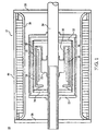
- a rotating machine 10 includes a stator assembly 12 and a rotor assembly 14 having, in this embodiment, a four pole topology.
- Rotor assembly 14 rotates within stator assembly 12 and, in this four pole configuration, includes four diametrically-opposed rotor coils 16, 17, 18, 19 (only two of which are shown in this figure), which are mounted on a support structure 20, which is substantially cylindrical.
- the construction and configuration of rotor coils 16, 18, which have substantially equal average mechanical densities, will be discussed below in greater detail. By setting these mechanical densities so that they are substantially equal, non-uniform, radial distortion (or ovalization) of the cylindrical support structure 20 can be reduced.
- Rotor assembly 14 includes a support member 22 attached to an output shaft 24, which is supported by a pair of bearing plates 26, 28, one at each end of rotor assembly 14.
- Support member 22 is typically fabricated from a high-strength, ductile, and non-magnetic material (e.g., stainless steel, copper, aluminum, phenolic, etc.).
- a torque tube 30 connects support member 22 to one of the two end plates 32, 34 of rotor assembly 14, thus establishing a torque path between support structure 20 and output shaft 24.
- the details of one embodiment of torque tube 30 are described in U.S. Application No. 09/909,412, filed July 19, 2001 , entitled "Torque Transmission Assembly For Use In Superconducting Rotating Machines"
- a vacuum chamber sleeve 36 surrounds the rotor coils 16, 18 and support structure 20.
- the ends of vacuum chamber sleeve 36 are connected to end plates 32, 34.
- vacuum chamber sleeve 36 is relatively thin (e.g., 0,48 cm 3 / 16 ") and is constructed of stainless steel.
- an air-tight chamber is formed which encloses the rotor coils 16, 18. This air-tight chamber may be evacuated, thus forming a vacuum within the chamber. This helps to insulate the cooler rotor coils 16, 18 from the warmer output shaft 24.
- Stator assembly 12 includes an armature winding 38 (e.g., a three phase stator winding) that is surrounded by an electromagnetic shield 40.
- Electromagnetic shield 40 is typically constructed of a non-magnetic material, such as copper, aluminum, phenolic, or stainless steel.
- a voltage source (not shown, e.g., a generator, a utility line, etc.) provides a supply voltage to armature winding 38.
- Field energy is applied to rotor coils 16, 18.
- the field energy is typically a DC current, as rotor coils 16, 18 require a DC current to generate the magnetic field (and the magnetic flux) needed to link the rotor assembly 14 and the stator assembly 12.
- a rectifier /thyristor circuit (not shown) is employed to convert the AC current into a DC current.
- Rotor coils 16, 18 may be non-superconducting windings (e.g., copper windings) or HTS (High Temperature Superconductor) windings.
- HTS conductors are: thallium-barium-calcium-copper-oxide; bismuth-strontium-calcium-copper-oxide; mercury-barium-calcium-copper-oxide; yttrium-barium-copper-oxide, and magnesium diboride.
- rotating machine 10 includes a cryogenic cooler (not shown), which maintains the operating temperature of rotor coils 16, 18 at an operating temperature sufficiently low to enable the conductors to exhibit their superconducting characteristics.
- cryogenic cooler (not shown) The details of embodiments of the cryogenic cooler (not shown) are described in: U.S. Patent No. 6,347,522, issued February 19, 2002 , entitled “Cooling System for HTS Machines”; U.S. Patent No. 6,376,943, issued April 23, 2002 , entitled “Superconductor Rotor Cooling System” and U.S. Application No. 10/128,535, filed April 23, 2002 , entitled “Superconductor Rotor Cooling System”
- a rotor support structure 20 which is typically constructed of stainless steel is included, upon which are disposed rotor coils and filler material that define two regions.
- the first of the regions 42 receives rotor coils (i.e., "coil” regions), and the second of the regions 44 do not receive rotor coils (i.e., "filler” regions).
- the rotor coils and filler material are conformed to the shape of the rotor support structure.
- four rotor coils are included in rotor assembly 14. Therefore, rotor support structure 20 is divided into eight regions, four "coil” regions (one for each rotor coil), and four "filler” regions positioned between the four coil regions.
- filler material typically the material from which the "filler” regions are fabricated is referred to as filler material, as it fills the space or gap between the rotor coils.
- two rotor coils 16, 18 each include a pair of distal end portions 46, 48 and a convex center portion 50.
- a conductor 52 (either superconducting or non-superconducting) is repeatedly wound around a mandrel (e.g., mandrel 54).
- mandrel 54 (which is typically constructed of stainless steel, copper, aluminum, phenolic, etc.) determines the final shape of the rotor coil, e.g., rotor coil 16.
- Mandrel 54 includes a pair of distal end portions 56, 58 (one defining the top and one defining the bottom of mandrel 54) and a pair of convex center portions 60, 61 (one defining each side of mandrel 54). Accordingly, when the conductor 52 is wound around mandrel 54, the final shape of the rotor coils is determined by the mandrel 54 around which the conductor 52 is wound.
- the convex center portions 60, 61 of mandrel 54 has curved edges 62, 64 that are not parallel with each other and actually bulge out in the middle, such that the width of the middle of the pair of convex center portions is wider than the pair of convex center portions at either the top or bottom (i.e., where the pair of convex center portions 60, 61 abuts distal end portions 56, 58).
- the pair of convex center portions 60, 61 have a large radius of curvature (e.g., 127-254 cm 50-100 inches), which is selected based on the stiffness of the conductor, the size of the coil, and/or the mechanical properties of the insulation system.
- mandrel vary depending on the particular application and design on the machine.
- the mandrel is 30,5 cm ⁇ twelve inches long and 20,3 cm eight inches wide, and the variation in width along the convex center portions of the mandrel is approximately 2,54 cm ⁇ one inch.
- the rotor coil 16, 18 is formed, such that the cross-section of any portion of this rotor coil includes numerous cross sections of conductor 52, due to the conductor being repeatedly looped around the mandrel.
- the number of times that conductor 52 is wound around mandrel 54 varies depending on the design and application of machine 10. For a particular embodiment of machine 10, conductor 52 is wound around mandrel 54 one-hundred-eighty times.
- the conductor loop When conductor 52 is wound around the distal end portions of mandrel 54, the conductor loop is compressed such that the individual loops of the conductor within the rotor coil are compressed together.
- the amount of compression is inversely proportional to the radius of curvature of the mandrel.
- the periphery of the distal end portions 56, 58 of mandrel 54 are defined by a smaller radius than the periphery of the convex center portions 60, 61, the level of compression experienced by the conductor proximate the distal end portions 56, 58 of mandrel 54 is greater than the level of compression experienced by the conductors proximate the convex center portions 60, 61.
- the compression level of the conductors proximate the distal end portions 56, 58 may be as high as 140 kg/m 2 ⁇ 2.0 lb/in 2 (for a mandrel with distal end portions having a 12.7 cm ⁇ 5" radius), while the compression level of the conductors proximate the convex center portions 60, 61 may be 140 kg/m 2 ⁇ 0.20 lb/in 2 .
- This type of coil / mandrel configuration will provide an essentially uniform average turn thickness around the coils and, hence, improve the mechanical properties of the rotor coils. Additionally, this coil / mandrel configuration minimizes variations in tilt of the conductor, thus improving the repeatability of the coil thickness. Further, this configuration reduces the requirement for vertical clamping during coil fabrication and provides for lower cost mold equipment. Also, this configuration increases the area enclosed by the coil for a given external coil envelope, thus increasing coil dipole moment (and the torque produced). In short, this configuration allows for faster and less expensive coil fabrication, while improving coil performance.
- the level of compression experienced by the conductors proximate the convex center portions 60, 61 is enhanced, as the tension of the conductor that is wound around the mandrel is converted to a compressive force in which the conductors are compressed radially toward the center of the mandrel 54. Accordingly, due to the use of convex center portions 60, 61, the variation in compression of the conductors looped around the mandrel is reduced, resulting in the distal end portions 46, 48 and convex center portion 50 of the rotor coil having substantially equal mechanical densities.
- the average mechanical density is 5528 kg/m 3 ⁇ 0.20 pounds per cubic inch (for glass conductor insulation) and 6081 kg/m 3 ⁇ 0.22 pounds per cubic inch (for paper conductor insulation).
- the rotation of rotor assembly 14 will have an equal effect on all portions of the rotor coils.
- the rotor assembly spins at 3,600 rpm.
- the various components of the rotor assembly are subjected to centrifugal forces that vary based on the density of these rotor assembly components.
- the rotor assembly can be further balanced and its performance further enhanced. Specifically, if the mandrel has a higher density than the rotor coil surrounding it, during operation, the mandrel is subjected to greater centrifugal forces than the lower density rotor coil. Accordingly, non-uniform, radial distortion (or ovalization) occurs, as the mandrel is radially pulled away from the axis of rotation of the rotor assembly at a greater rate than the rotor coil surrounding it.
- the mandrel 54 may be constructed of a material that has a density substantially equal to the average density of the rotor coil. For example, if the average mechanical density of the rotor coil is ⁇ 0.20 pounds per cubic inch, the mandrel can be constructed from a material having a substantially equal mechanical density.
- a higher density material e.g., stainless steel, copper, aluminum, phenolic, etc.
- a higher density material e.g., stainless steel, copper, aluminum, phenolic, etc.
- the mandrel can be machined so that, on average, one third of the material of the mandrel is removed. This can be accomplished by machining holes 66, 68, 70 and/or slots 72, 74 into the mandrel, such that the surface area of mandrel 54 is reduced by the appropriate percentage.
- the desired mandrel density is 558/m 3 kg ⁇ 0.20 lbs. / inch 3 and the actual mandrel density is 8292 kg/m 3 ⁇ 0.30 lbs. / inch 3
- the actual density of the mandrel is 50% greater than required. Therefore, when machining in the holes and/or slots into the mandrel, the holes and/or slots should occupy one-third of the mandrel's surface area. When machining these holes and/or slots, their size should be kept to a minimum and spatial frequency kept to a maximum to homogenize the density distribution throughout the mandrel. A typical example of the size and spatial frequency of these holes is one-half inch diameter holes on two inch centers.
- An alternative way of reducing the density of the mandrel is to reduce the thickness of the mandrel by the requisite amount. Accordingly, if the mandrel was reduced in thickness by one third, the same net result would be achieved, as the average density of the mandrel would be reduced by one-third.
- rotor support structure 20 is divided into two types of regions, "coil” regions 42 and “filler” regions 44, such that the "coil” regions 42 receive one or more rotor coils and the "filler” regions 44 receive a filler material (e.g., stainless steel, copper, aluminum, phenolic, etc.) that fills the space or gap between the rotor coils (i.e., the "coil” regions 42).
- filler material 76 is typically a substantially hour-glass shaped piece of stainless steel that is rolled to the appropriate radius of rotor support structure 20, so as to accommodate the shape of the rotor coils and the support structure.
- Rotor assembly 14 may be further balanced and performance further enhanced by matching the mechanical density of the filler material 76 (i.e., the "filler" region) to that of the rotor coil 16, 18 and mandrel 54.
- the filler material 76 i.e., the "filler” region
- the filler material 76 is subjected to greater centrifugal forces than the lower density rotor coil /mandrel combination. Accordingly, non-uniform, radial distortion (or ovalization) occurs, as the filler material 76 is radially pulled away from the axis of rotation of rotor assembly 14 at a greater rate than the rotor coil / mandrel combination.
- the mandrel 54 there are several ways to match the filler material mechanical average density to that of the average mechanical density of the rotor coil / mandrel combination.
- the filler material 76 may be constructed of a material that has a density substantially equal to the average density of the rotor coil / mandrel combination.
- a higher density material such as stainless steel, copper, aluminum, or phenolic, may be used, provided the material is machined to lower its average mechanical density. As explained above, this may be accomplished by, for example, machining holes 78, 80, 82 and/or slots 84, 86 in filler material 76, such that the surface area of the filler material is reduced by the appropriate percentage.
- machining holes 78, 80, 82 and/or slots 84, 86 in filler material 76, such that the surface area of the filler material is reduced by the appropriate percentage.
- their size should be kept to a minimum and spatial frequency kept to a maximum to homogenize the density distribution throughout the filler material.
- a typical example of the size and spatial frequency of these holes is 1,27 cm ⁇ one-half inch diameter holes on 5,08 cm ⁇ two inch centers.
- An alternative way of reducing the density of the filler material 76 is to reduce its thickness by the requisite amount. Accordingly, if the density of the filler material needs to be reduced by one-third, the thickness of the filler material 76 could be reduced by one-third and the required mechanical density reduction would be achieved.
- armature winding 38 is described above as a three-phase armature winding, other configurations are possible.
- armature winding 38 may be a single-phase armature winding.
- mandrel 54 is described above as having a pair of distal end portion 56, 58 having a first radius and a pair of convex center portions 60, 61 having a second radius, other configuration are possible.
- mandrel 54 may be elliptical in shape and, therefore, have a continually varying radius.
- support member 22 is described above as being fabricated of a non-magnetic material (e.g., aluminum), support member 22 may be constructed of a magnetic material (e.g., iron).
- support member is an iron core 22' formed from a series of stacked laminations. The stacked laminations, which may or may not be cooled by the cryogenic cooler, are placed within the inner volume of the cylindrical support structure 20. The torque tube 30 is then allowed to cool so that the tube shrinks around the laminations, capturing the laminations in a compressed state within the tube. Torque tube 30 may also be "shrink welded" to preload the torque tube around the iron core.
- a solid iron core may be used, a stacked set of laminations is preferable so that if one of the laminations cracks, the crack is isolated to that lamination and will not propagate to neighboring laminations. Cracking in the iron core can be a serious concern if the non-ductile iron core is cryogenically cooled along with the rotor coils 16, 17, 18, 19. At cryogenically-low temperatures, the brittleness characteristic of the iron is increased.
- reinforcing layers e.g., fiberglass or stainless steel
- the laminations and reinforcing layers can then be impregnated with, for example, epoxy.
- the positioning the iron core 22' within the torque tube provides significant advantages in the operation of the rotating machine 10.
- the rotor coils should be positioned in close radial proximity to iron core 22'.
- a simplistic representation of the flux paths generated by each of the rotor coils superconducting windings is shown.
- the flux path extends counterclockwise through the back iron member and, then back along a path 96 parallel to axis 98 toward point 88 to close the loop.
- the flux paths for the remaining quadrants extend away from the iron core, through the back iron member and back to the iron core in similar fashion.
- iron is a high saturation flux density material (i.e., approximately 2.0 Tesla), it acts, in a sense, as a magnetic short circuit so as to reduce the overall reluctance of the flux path and increase the amount of flux generated for a given number of ampere-turns of the windings. Thus, a lower-loss magnetic circuit is provided resulting in a more efficient motor.
- a plot showing the magnetic field distribution within the rotor assembly 14 shows the increased flux flowing through the iron core 22'.
- rotor coils 16, 18 are described above as including a convex center portion 50, other configurations are possible.
- the center portion may have parallel sides and, therefore, the center portion would be rectangular in shape, as opposed to convex.
- Racetrack-type coil 100 is typically constructed of several coil windings (e.g., windings 102,104,106) that are stacked on top of each other.
- FIG. 8 there is shown a cross-sectional view of an alternative embodiment of the rotor coil 16' in which the conductor 52 used to wind the rotor coil is wound around a mandrel 54', such that the periphery of the convex center portions 60', 61' of the mandrel 54' is perpendicular to the surface 108 of the rotor support structure 20. Accordingly, the individual conductors positioned proximate the convex center portions 60', 61' of the mandrel 54' are perpendicular to the surface 108 of the rotor support structure 20.
- the broad face of the conductor 52 is also positioned perpendicular to the surface 108 of the rotor support structure 20. Accordingly, this rotor coil configuration radially aligns (i.e., toward the axial centerline of the rotor assembly) the lines of magnetic flux (e.g., flux lines 110, 112, 114) produced by the individual conductors wound around the mandrel 54', as the lines of magnetic flux are parallel with the broad face of conductor 52.
- the lines of magnetic flux e.g., flux lines 110, 112, 114
- this coil configuration produces a rotor coil having a convex exterior surface 116
- the rotor coil can be positioned tightly against the rotor support structure.
- the concave interior surface 118 of this configuration of the rotor coil allows it to be positioned in close proximately with iron core 22.
Landscapes
- Engineering & Computer Science (AREA)
- Power Engineering (AREA)
- Superconductive Dynamoelectric Machines (AREA)
- Windings For Motors And Generators (AREA)
- Insulation, Fastening Of Motor, Generator Windings (AREA)
Claims (15)
- Rotoranordnung (14), die Folgendes umfasst:- eine im Wesentlichen zylindrische Stützstruktur (20); und- mindestens eine Rotorwicklung (16, 17, 18, 19), die durch die Stützstruktur (20) gestützt wird;dadurch gekennzeichnet, dass
die Stützstruktur (20) in mindestens eine erste Region (42), auf der die mindestens eine Rotorwicklung (16, 17, 18, 19) angeordnet ist, und mindestens eine zweite Region (44), auf der ein Füllmaterial, das den Spalt zwischen den Rotorwicklungen ausfüllt, und keine Rotorwicklung angeordnet ist, unterteilt ist;
ein Dorn (54) eine innere Region der Rotorwicklung belegt und eine durchschnittliche Dichte aufweist, die an die durchschnittliche Dichte der Rotorwicklung (16, 17, 18, 19) angepasst ist; und
die durchschnittliche Dichte des Füllmaterials an die durchschnittliche Dichte der Rotorwicklung (16, 17, 18, 19) und des Dorns (54) angepasst ist. - Rotoranordnung (14) nach Anspruch 1,
wobei jede Rotorwicklung (16, 17, 18, 19) ein Paar distaler Endabschnitte (46, 48) und einen konvexen Mittelabschnitt (50) umfasst; und
wobei die durchschnittliche mechanische Dichte des konvexen Mittelabschnitts (50) gleich der durchschnittlichen mechanischen Dichte der distalen Endabschnitte (46, 48) ist. - Rotoranordnung (14) nach Anspruch 1, wobei der Dorn (54) aus einem Material besteht, dessen mechanische Dichte größer ist als die durchschnittliche mechanische Dichte der Rotorwicklung (16, 17, 18, 19).
- Rotoranordnung (14) nach Anspruch 1, wobei der Dorn (54) aus einem Material besteht, dessen mechanische Dichte gleich der durchschnittlichen mechanischen Dichte der Rotorwicklung (16, 17, 18, 19) ist.
- Rotoranordnung (14) nach Anspruch 1, wobei der Dorn (54) aus einem Material besteht, das aus der Gruppe enthaltend Edelstahl, Aluminium, Phenol und Kupfer ausgewählt ist.
- Rotoranordnung (14) nach Anspruch 1, wobei der Dorn (54) ein Paar distaler Endabschnitte (56, 58) umfasst, die durch ein Paar konvexer Mittelabschnitte (60, 61) voneinander beabstandet sind.
- Rotoranordnung (14) nach Anspruch 6, wobei der Umfangsrand der distalen Endabschnitte (56, 58) des Dorns (54) durch einen ersten Radius definiert wird und der Umfangsrand der konvexen Mittelabschnitte (60, 61) des Dorns (54) durch einen zweiten Radius definiert wird, der größer als der erste Radius ist.
- Rotoranordnung (14) nach Anspruch 1, wobei der Dorn (54) ein elliptischer Dorn (54) ist.
- Rotoranordnung (14) nach Anspruch 1, wobei die Rotorwicklung (16, 17, 18, 19) eine Wicklung vom Rennbahntyp oder eine Wicklung vom Satteltyp ist.
- Rotoranordnung (14) nach Anspruch 9, wobei die Rotorwicklung (16, 17, 18, 19) eine Wicklung vom Rennbahntyp ist, die so ausgebildet ist, dass die Magnetflusslinien, die durch die Wicklung vom Rennbahntyp erzeugt werden, senkrecht zu einer Oberfläche der im Wesentlichen zylindrischen Stützstruktur (20) verlaufen und radial in Richtung einer axialen Mittellinie der Rotoranordnung (14) ausgerichtet sind.
- Rotoranordnung (14) nach Anspruch 1 oder 2, wobei die Rotorwicklung (16, 17, 18, 19) eine supraleitende Rotorwicklung (16, 17, 18, 19) ist, insbesondere eine supraleitende Rotorwicklung (16, 17, 18, 19), die eine oder mehrere supraleitende Hochtemperaturwicklungen umfasst.
- Rotoranordnung (14) nach Anspruch 1 oder 2, wobei die mindestens eine Rotorwicklung (16, 17, 18, 19) während des Betriebes einen Magnetflusspfad innerhalb der Rotoranordnung (14) erzeugt und die im Wesentlichen zylindrische Stützstruktur (20) ein Innenvolumen definiert, wobei die Rotoranordnung (14) des Weiteren Folgendes umfasst:- ein magnetisches Material, das eine Flussdichte mit hoher Sättigung aufweist und innerhalb des Innenvolumens der im Wesentlichen zylindrischen Stützstruktur (20) und mindestens eines Abschnitts des Flusspfades angeordnet ist, um die Gesamtreluktanz des durch die mindestens eine Rotorwicklung (16, 17, 18, 19) erzeugten Flusspfades zu verringern.
- Rotoranordnung (14) nach Anspruch 12, wobei das magnetische Material innerhalb des Innenvolumens kryogenisch gekühlt wird.
- Rotoranordnung (14) nach Anspruch 1, wobei der Dorn (54) Aussparungen (66, 68, 70, 72, 74) umfasst.
- Rotoranordnung (14) nach Anspruch 8, wobei die Rotorwicklung (16, 17, 18, 19) eine Wicklung vom Satteltyp ist, die so ausgebildet ist, dass die durch die Wicklung vom Satteltyp erzeugten Magnetflusslinien senkrecht zu einer Oberfläche der im Wesentlichen zylindrischen Stützstruktur (20) verlaufen und radial in Richtung einer axialen Mittellinie der Rotoranordnung (14) ausgerichtet sind.
Applications Claiming Priority (3)
| Application Number | Priority Date | Filing Date | Title |
|---|---|---|---|
| US10/367,125 US6759781B1 (en) | 2003-02-14 | 2003-02-14 | Rotor assembly |
| PCT/US2004/003978 WO2004075383A1 (en) | 2003-02-14 | 2004-02-10 | A rotor assembly |
| US367125 | 2009-02-06 |
Publications (2)
| Publication Number | Publication Date |
|---|---|
| EP1593194A1 EP1593194A1 (de) | 2005-11-09 |
| EP1593194B1 true EP1593194B1 (de) | 2012-10-03 |
Family
ID=32594986
Family Applications (1)
| Application Number | Title | Priority Date | Filing Date |
|---|---|---|---|
| EP04709900A Expired - Lifetime EP1593194B1 (de) | 2003-02-14 | 2004-02-10 | Rotoranordnung |
Country Status (6)
| Country | Link |
|---|---|
| US (2) | US6759781B1 (de) |
| EP (1) | EP1593194B1 (de) |
| JP (1) | JP4376869B2 (de) |
| KR (1) | KR100761432B1 (de) |
| CN (1) | CN100574061C (de) |
| WO (1) | WO2004075383A1 (de) |
Families Citing this family (17)
| Publication number | Priority date | Publication date | Assignee | Title |
|---|---|---|---|---|
| US6759781B1 (en) * | 2003-02-14 | 2004-07-06 | American Superconductor Corporation | Rotor assembly |
| US6885120B2 (en) * | 2003-07-14 | 2005-04-26 | General Electric Company | Structural enclosed rotor configuration for electric machine |
| JP4732053B2 (ja) * | 2005-07-27 | 2011-07-27 | 東芝三菱電機産業システム株式会社 | 超電導回転電機の回転子 |
| US20070052304A1 (en) * | 2005-09-07 | 2007-03-08 | Philippe Masson | Multi-pattern high temperature superconducting motor using flux trapping and concentration |
| US8021135B2 (en) * | 2007-06-08 | 2011-09-20 | Sabic Innovative Plastics Ip B.V. | Mold apparatus for forming polymer and method |
| EP2212079A1 (de) * | 2007-10-26 | 2010-08-04 | SABIC Innovative Plastics IP B.V. | System und verfahren zur herstellung eines polymeres |
| US7834509B2 (en) * | 2008-02-28 | 2010-11-16 | Hamilton Sundstrand Corporation | Rotor assembly for electromechanical machine |
| US20090224550A1 (en) * | 2008-03-06 | 2009-09-10 | General Electric Company | Systems involving superconducting direct drive generators for wind power applications |
| JP5190093B2 (ja) * | 2010-07-26 | 2013-04-24 | 株式会社日立製作所 | 超電導コイルおよびそれを用いた超電導回転機 |
| US8791052B2 (en) | 2012-03-30 | 2014-07-29 | American Superconductor Corporation | Wide electrical conductor having high C-axis strength |
| US9455604B2 (en) | 2012-10-16 | 2016-09-27 | Hamilton Sundstrand Corporation | Wound-field synchronous machine including rotor damper-sleeve |
| KR101827463B1 (ko) | 2014-06-27 | 2018-02-08 | 사빅 글로벌 테크놀러지스 비.브이. | 다재료 코어를 갖는 유도 가열 금형 장치 및 이의 사용 방법 |
| DE102016217734A1 (de) * | 2016-09-16 | 2018-03-22 | Siemens Aktiengesellschaft | Rotor mit Spulenanordnung und Wicklungsträger |
| CN106972734A (zh) * | 2017-05-25 | 2017-07-21 | 华北电力大学 | 一种采用跑道形超导片堆叠线圈的超导电机 |
| US10601299B2 (en) * | 2017-09-07 | 2020-03-24 | American Superconductor Corporation | High temperature superconductor generator with increased rotational inertia |
| US11159069B2 (en) * | 2018-10-04 | 2021-10-26 | Hamilton Sundstrand Corporation | Embedded liquid cooled rotor cooling |
| US20250246947A1 (en) * | 2024-01-26 | 2025-07-31 | Elberto Berdut-Teruel | Converter of Static Magnetic Energy into Dynamic Mechanical Energy |
Family Cites Families (20)
| Publication number | Priority date | Publication date | Assignee | Title |
|---|---|---|---|---|
| US3436571A (en) * | 1967-03-13 | 1969-04-01 | Trw Inc | Dynamoelectric machine having corresponding ferromagnetic coils on alternating rotor and stator disks |
| AT300096B (de) * | 1970-02-20 | 1972-07-10 | Interelectric Ag | Ausgewuchtete Rotorwicklung für elektrische Maschinen |
| US4130769A (en) * | 1974-11-01 | 1978-12-19 | Canon Kabushiki Kaisha | Brushless DC motor |
| UST945003I4 (de) * | 1975-01-02 | 1976-04-06 | ||
| US4203048A (en) * | 1976-09-14 | 1980-05-13 | Olympus Optical Co., Ltd. | Coil support for disc rotor of coreless motor |
| SU873338A1 (ru) * | 1979-02-15 | 1981-10-15 | Предприятие П/Я Р-6794 | Ротор криогенной электрической машины |
| US4468579A (en) * | 1981-09-04 | 1984-08-28 | Alps Electric Co., Ltd. | Small motor |
| JPS5963971A (ja) * | 1982-10-05 | 1984-04-11 | Nippon Soken Inc | 電磁駆動装置 |
| DE3683221D1 (de) * | 1985-08-14 | 1992-02-13 | Philips Patentverwaltung | Optische abtasteinheit. |
| US5210452A (en) * | 1991-08-06 | 1993-05-11 | Board Of Regents, The University Of Texas System | Symmetric armature for high current, air-core pulsed alternators |
| WO1994020992A1 (en) * | 1993-03-04 | 1994-09-15 | American Superconductor Corporation | Magnetostrictive superconducting actuator |
| US5482919A (en) * | 1993-09-15 | 1996-01-09 | American Superconductor Corporation | Superconducting rotor |
| DE4414527C1 (de) * | 1994-04-26 | 1995-08-31 | Orto Holding Ag | Elektronisch kommutierte Gleichstrommaschine |
| US5744896A (en) * | 1996-05-21 | 1998-04-28 | Visual Computing Systems Corp. | Interlocking segmented coil array |
| AU2001230723A1 (en) * | 2000-01-11 | 2001-07-24 | American Superconductor Corporation | Hts superconducting rotating machine |
| DE10060121A1 (de) * | 2000-12-04 | 2002-06-06 | Alstom Switzerland Ltd | Verfahren zur Herstellung eines Permanentmagnete enthaltenden Rotors einer Synchronmaschine und nach diesem Verfahren hergestellter Rotor |
| US6922885B2 (en) * | 2001-05-15 | 2005-08-02 | General Electric Company | High temperature superconducting racetrack coil |
| US6700274B2 (en) * | 2001-07-19 | 2004-03-02 | American Superconductor Corporation | Torque transmission assembly for use in superconducting rotating machines |
| US6791230B2 (en) * | 2001-09-07 | 2004-09-14 | Honeywell International, Inc. | System and method for retaining wedges in a rotor |
| US6759781B1 (en) * | 2003-02-14 | 2004-07-06 | American Superconductor Corporation | Rotor assembly |
-
2003
- 2003-02-14 US US10/367,125 patent/US6759781B1/en not_active Expired - Lifetime
-
2004
- 2004-02-10 JP JP2005518579A patent/JP4376869B2/ja not_active Expired - Fee Related
- 2004-02-10 WO PCT/US2004/003978 patent/WO2004075383A1/en not_active Ceased
- 2004-02-10 EP EP04709900A patent/EP1593194B1/de not_active Expired - Lifetime
- 2004-02-10 CN CNB2004800066287A patent/CN100574061C/zh not_active Expired - Fee Related
- 2004-02-10 KR KR1020057014816A patent/KR100761432B1/ko not_active Expired - Lifetime
- 2004-07-06 US US10/885,509 patent/US20050077797A1/en not_active Abandoned
Also Published As
| Publication number | Publication date |
|---|---|
| US20050077797A1 (en) | 2005-04-14 |
| CN1759524A (zh) | 2006-04-12 |
| EP1593194A1 (de) | 2005-11-09 |
| KR100761432B1 (ko) | 2007-09-27 |
| CN100574061C (zh) | 2009-12-23 |
| KR20050101331A (ko) | 2005-10-21 |
| JP4376869B2 (ja) | 2009-12-02 |
| JP2006515501A (ja) | 2006-05-25 |
| US6759781B1 (en) | 2004-07-06 |
| WO2004075383A1 (en) | 2004-09-02 |
Similar Documents
| Publication | Publication Date | Title |
|---|---|---|
| EP0913023B1 (de) | Aufbau eines supraleitenden synchronmotors | |
| US6489701B1 (en) | Superconducting rotating machines | |
| US6759781B1 (en) | Rotor assembly | |
| US7489060B2 (en) | Superconducting rotating machines with stationary field coils | |
| US7119644B2 (en) | Mounting structure for superconducting windings | |
| US8084909B2 (en) | Dual armature motor/generator with flux linkage | |
| US6603231B2 (en) | Hybrid superconducting motor/generator | |
| US8212437B2 (en) | Superconducting multi-pole electrical machine | |
| US20090009012A1 (en) | Assembly and method for magnetization of permanent magnet rotors in electrical machines | |
| KR101530140B1 (ko) | 전기 기계용 고정자 및 전기 기계 | |
| US7492073B2 (en) | Superconducting rotating machines with stationary field coils | |
| EP3734811A1 (de) | Magnetische abschirmung für einen supraleitenden generator | |
| US4987674A (en) | Method of making a dynamoelectric machine with superconducting magnet rotor | |
| US6590308B2 (en) | High power density super-conducting electric machine | |
| US7291958B2 (en) | Rotating back iron for synchronous motors/generators | |
| US6795720B2 (en) | High temperature superconducting synchronous rotor coil having multi-piece rotor core | |
| Jang et al. | Conceptual design of 100 HP synchronous motor with HTS field winding | |
| JPS6244062A (ja) | 超電導回転子 |
Legal Events
| Date | Code | Title | Description |
|---|---|---|---|
| PUAI | Public reference made under article 153(3) epc to a published international application that has entered the european phase |
Free format text: ORIGINAL CODE: 0009012 |
|
| 17P | Request for examination filed |
Effective date: 20050826 |
|
| AK | Designated contracting states |
Kind code of ref document: A1 Designated state(s): AT BE BG CH CY CZ DE DK EE ES FI FR GB GR HU IE IT LI LU MC NL PT RO SE SI SK TR |
|
| AX | Request for extension of the european patent |
Extension state: AL LT LV MK |
|
| DAX | Request for extension of the european patent (deleted) | ||
| 17Q | First examination report despatched |
Effective date: 20070510 |
|
| GRAP | Despatch of communication of intention to grant a patent |
Free format text: ORIGINAL CODE: EPIDOSNIGR1 |
|
| GRAS | Grant fee paid |
Free format text: ORIGINAL CODE: EPIDOSNIGR3 |
|
| GRAA | (expected) grant |
Free format text: ORIGINAL CODE: 0009210 |
|
| AK | Designated contracting states |
Kind code of ref document: B1 Designated state(s): AT BE BG CH CY CZ DE DK EE ES FI FR GB GR HU IE IT LI LU MC NL PT RO SE SI SK TR |
|
| REG | Reference to a national code |
Ref country code: GB Ref legal event code: FG4D |
|
| REG | Reference to a national code |
Ref country code: AT Ref legal event code: REF Ref document number: 578374 Country of ref document: AT Kind code of ref document: T Effective date: 20121015 Ref country code: CH Ref legal event code: EP |
|
| REG | Reference to a national code |
Ref country code: IE Ref legal event code: FG4D |
|
| REG | Reference to a national code |
Ref country code: DE Ref legal event code: R096 Ref document number: 602004039528 Country of ref document: DE Effective date: 20121129 |
|
| REG | Reference to a national code |
Ref country code: AT Ref legal event code: MK05 Ref document number: 578374 Country of ref document: AT Kind code of ref document: T Effective date: 20121003 |
|
| PG25 | Lapsed in a contracting state [announced via postgrant information from national office to epo] |
Ref country code: SI Free format text: LAPSE BECAUSE OF FAILURE TO SUBMIT A TRANSLATION OF THE DESCRIPTION OR TO PAY THE FEE WITHIN THE PRESCRIBED TIME-LIMIT Effective date: 20121003 |
|
| REG | Reference to a national code |
Ref country code: NL Ref legal event code: VDEP Effective date: 20121003 |
|
| PG25 | Lapsed in a contracting state [announced via postgrant information from national office to epo] |
Ref country code: NL Free format text: LAPSE BECAUSE OF FAILURE TO SUBMIT A TRANSLATION OF THE DESCRIPTION OR TO PAY THE FEE WITHIN THE PRESCRIBED TIME-LIMIT Effective date: 20121003 Ref country code: FI Free format text: LAPSE BECAUSE OF FAILURE TO SUBMIT A TRANSLATION OF THE DESCRIPTION OR TO PAY THE FEE WITHIN THE PRESCRIBED TIME-LIMIT Effective date: 20121003 Ref country code: SE Free format text: LAPSE BECAUSE OF FAILURE TO SUBMIT A TRANSLATION OF THE DESCRIPTION OR TO PAY THE FEE WITHIN THE PRESCRIBED TIME-LIMIT Effective date: 20121003 Ref country code: ES Free format text: LAPSE BECAUSE OF FAILURE TO SUBMIT A TRANSLATION OF THE DESCRIPTION OR TO PAY THE FEE WITHIN THE PRESCRIBED TIME-LIMIT Effective date: 20130114 |
|
| PG25 | Lapsed in a contracting state [announced via postgrant information from national office to epo] |
Ref country code: PT Free format text: LAPSE BECAUSE OF FAILURE TO SUBMIT A TRANSLATION OF THE DESCRIPTION OR TO PAY THE FEE WITHIN THE PRESCRIBED TIME-LIMIT Effective date: 20130204 Ref country code: BE Free format text: LAPSE BECAUSE OF FAILURE TO SUBMIT A TRANSLATION OF THE DESCRIPTION OR TO PAY THE FEE WITHIN THE PRESCRIBED TIME-LIMIT Effective date: 20121003 Ref country code: CY Free format text: LAPSE BECAUSE OF FAILURE TO SUBMIT A TRANSLATION OF THE DESCRIPTION OR TO PAY THE FEE WITHIN THE PRESCRIBED TIME-LIMIT Effective date: 20121003 Ref country code: GR Free format text: LAPSE BECAUSE OF FAILURE TO SUBMIT A TRANSLATION OF THE DESCRIPTION OR TO PAY THE FEE WITHIN THE PRESCRIBED TIME-LIMIT Effective date: 20130104 |
|
| PG25 | Lapsed in a contracting state [announced via postgrant information from national office to epo] |
Ref country code: AT Free format text: LAPSE BECAUSE OF FAILURE TO SUBMIT A TRANSLATION OF THE DESCRIPTION OR TO PAY THE FEE WITHIN THE PRESCRIBED TIME-LIMIT Effective date: 20121003 |
|
| PG25 | Lapsed in a contracting state [announced via postgrant information from national office to epo] |
Ref country code: CZ Free format text: LAPSE BECAUSE OF FAILURE TO SUBMIT A TRANSLATION OF THE DESCRIPTION OR TO PAY THE FEE WITHIN THE PRESCRIBED TIME-LIMIT Effective date: 20121003 Ref country code: DK Free format text: LAPSE BECAUSE OF FAILURE TO SUBMIT A TRANSLATION OF THE DESCRIPTION OR TO PAY THE FEE WITHIN THE PRESCRIBED TIME-LIMIT Effective date: 20121003 Ref country code: SK Free format text: LAPSE BECAUSE OF FAILURE TO SUBMIT A TRANSLATION OF THE DESCRIPTION OR TO PAY THE FEE WITHIN THE PRESCRIBED TIME-LIMIT Effective date: 20121003 Ref country code: EE Free format text: LAPSE BECAUSE OF FAILURE TO SUBMIT A TRANSLATION OF THE DESCRIPTION OR TO PAY THE FEE WITHIN THE PRESCRIBED TIME-LIMIT Effective date: 20121003 Ref country code: BG Free format text: LAPSE BECAUSE OF FAILURE TO SUBMIT A TRANSLATION OF THE DESCRIPTION OR TO PAY THE FEE WITHIN THE PRESCRIBED TIME-LIMIT Effective date: 20130103 |
|
| PLBE | No opposition filed within time limit |
Free format text: ORIGINAL CODE: 0009261 |
|
| STAA | Information on the status of an ep patent application or granted ep patent |
Free format text: STATUS: NO OPPOSITION FILED WITHIN TIME LIMIT |
|
| PG25 | Lapsed in a contracting state [announced via postgrant information from national office to epo] |
Ref country code: RO Free format text: LAPSE BECAUSE OF FAILURE TO SUBMIT A TRANSLATION OF THE DESCRIPTION OR TO PAY THE FEE WITHIN THE PRESCRIBED TIME-LIMIT Effective date: 20121003 |
|
| 26N | No opposition filed |
Effective date: 20130704 |
|
| PG25 | Lapsed in a contracting state [announced via postgrant information from national office to epo] |
Ref country code: MC Free format text: LAPSE BECAUSE OF NON-PAYMENT OF DUE FEES Effective date: 20130228 |
|
| REG | Reference to a national code |
Ref country code: CH Ref legal event code: PL |
|
| PG25 | Lapsed in a contracting state [announced via postgrant information from national office to epo] |
Ref country code: CH Free format text: LAPSE BECAUSE OF NON-PAYMENT OF DUE FEES Effective date: 20130228 Ref country code: LI Free format text: LAPSE BECAUSE OF NON-PAYMENT OF DUE FEES Effective date: 20130228 |
|
| REG | Reference to a national code |
Ref country code: DE Ref legal event code: R097 Ref document number: 602004039528 Country of ref document: DE Effective date: 20130704 |
|
| REG | Reference to a national code |
Ref country code: IE Ref legal event code: MM4A |
|
| PG25 | Lapsed in a contracting state [announced via postgrant information from national office to epo] |
Ref country code: IE Free format text: LAPSE BECAUSE OF NON-PAYMENT OF DUE FEES Effective date: 20130210 |
|
| PGFP | Annual fee paid to national office [announced via postgrant information from national office to epo] |
Ref country code: IT Payment date: 20150224 Year of fee payment: 12 |
|
| PG25 | Lapsed in a contracting state [announced via postgrant information from national office to epo] |
Ref country code: TR Free format text: LAPSE BECAUSE OF FAILURE TO SUBMIT A TRANSLATION OF THE DESCRIPTION OR TO PAY THE FEE WITHIN THE PRESCRIBED TIME-LIMIT Effective date: 20121003 |
|
| PG25 | Lapsed in a contracting state [announced via postgrant information from national office to epo] |
Ref country code: HU Free format text: LAPSE BECAUSE OF FAILURE TO SUBMIT A TRANSLATION OF THE DESCRIPTION OR TO PAY THE FEE WITHIN THE PRESCRIBED TIME-LIMIT; INVALID AB INITIO Effective date: 20040210 Ref country code: LU Free format text: LAPSE BECAUSE OF NON-PAYMENT OF DUE FEES Effective date: 20130210 |
|
| REG | Reference to a national code |
Ref country code: FR Ref legal event code: PLFP Year of fee payment: 13 |
|
| PG25 | Lapsed in a contracting state [announced via postgrant information from national office to epo] |
Ref country code: IT Free format text: LAPSE BECAUSE OF NON-PAYMENT OF DUE FEES Effective date: 20160210 |
|
| REG | Reference to a national code |
Ref country code: FR Ref legal event code: PLFP Year of fee payment: 14 |
|
| REG | Reference to a national code |
Ref country code: FR Ref legal event code: PLFP Year of fee payment: 15 |
|
| PGFP | Annual fee paid to national office [announced via postgrant information from national office to epo] |
Ref country code: FR Payment date: 20230223 Year of fee payment: 20 |
|
| PGFP | Annual fee paid to national office [announced via postgrant information from national office to epo] |
Ref country code: GB Payment date: 20230227 Year of fee payment: 20 Ref country code: DE Payment date: 20230223 Year of fee payment: 20 |
|
| P01 | Opt-out of the competence of the unified patent court (upc) registered |
Effective date: 20230810 |
|
| REG | Reference to a national code |
Ref country code: DE Ref legal event code: R071 Ref document number: 602004039528 Country of ref document: DE |
|
| REG | Reference to a national code |
Ref country code: GB Ref legal event code: PE20 Expiry date: 20240209 |
|
| PG25 | Lapsed in a contracting state [announced via postgrant information from national office to epo] |
Ref country code: GB Free format text: LAPSE BECAUSE OF EXPIRATION OF PROTECTION Effective date: 20240209 |