EP1592183A1 - Procede d'etablissement d'itineraire de transfert multidiffusion, et procede de commutation d'etiquette multidiffusion permettant de mettre en oeuvre le procede susmentionne - Google Patents
Procede d'etablissement d'itineraire de transfert multidiffusion, et procede de commutation d'etiquette multidiffusion permettant de mettre en oeuvre le procede susmentionne Download PDFInfo
- Publication number
- EP1592183A1 EP1592183A1 EP04708880A EP04708880A EP1592183A1 EP 1592183 A1 EP1592183 A1 EP 1592183A1 EP 04708880 A EP04708880 A EP 04708880A EP 04708880 A EP04708880 A EP 04708880A EP 1592183 A1 EP1592183 A1 EP 1592183A1
- Authority
- EP
- European Patent Office
- Prior art keywords
- route
- multicast
- delay
- computing
- ending
- Prior art date
- Legal status (The legal status is an assumption and is not a legal conclusion. Google has not performed a legal analysis and makes no representation as to the accuracy of the status listed.)
- Withdrawn
Links
- 238000012546 transfer Methods 0.000 title claims abstract description 250
- 238000000034 method Methods 0.000 title claims abstract description 74
- 238000005259 measurement Methods 0.000 claims abstract description 70
- 230000000295 complement effect Effects 0.000 claims abstract description 64
- 238000004590 computer program Methods 0.000 claims description 25
- 238000004891 communication Methods 0.000 claims description 20
- 230000005540 biological transmission Effects 0.000 claims description 4
- 230000009467 reduction Effects 0.000 abstract description 2
- 238000010586 diagram Methods 0.000 description 31
- 229920003266 Leaf® Polymers 0.000 description 16
- 238000012545 processing Methods 0.000 description 16
- 230000007246 mechanism Effects 0.000 description 5
- 238000007796 conventional method Methods 0.000 description 4
- 230000004044 response Effects 0.000 description 4
- 230000008569 process Effects 0.000 description 3
- 230000011664 signaling Effects 0.000 description 3
- 230000008859 change Effects 0.000 description 2
- 235000008694 Humulus lupulus Nutrition 0.000 description 1
- 238000006243 chemical reaction Methods 0.000 description 1
- 230000001934 delay Effects 0.000 description 1
- 238000010380 label transfer Methods 0.000 description 1
- 238000012986 modification Methods 0.000 description 1
- 230000004048 modification Effects 0.000 description 1
- 230000006855 networking Effects 0.000 description 1
- 239000004065 semiconductor Substances 0.000 description 1
- 230000007727 signaling mechanism Effects 0.000 description 1
- 238000011144 upstream manufacturing Methods 0.000 description 1
Images


Classifications
-
- H—ELECTRICITY
- H04—ELECTRIC COMMUNICATION TECHNIQUE
- H04L—TRANSMISSION OF DIGITAL INFORMATION, e.g. TELEGRAPHIC COMMUNICATION
- H04L45/00—Routing or path finding of packets in data switching networks
- H04L45/48—Routing tree calculation
-
- H—ELECTRICITY
- H04—ELECTRIC COMMUNICATION TECHNIQUE
- H04L—TRANSMISSION OF DIGITAL INFORMATION, e.g. TELEGRAPHIC COMMUNICATION
- H04L45/00—Routing or path finding of packets in data switching networks
- H04L45/12—Shortest path evaluation
-
- H—ELECTRICITY
- H04—ELECTRIC COMMUNICATION TECHNIQUE
- H04L—TRANSMISSION OF DIGITAL INFORMATION, e.g. TELEGRAPHIC COMMUNICATION
- H04L45/00—Routing or path finding of packets in data switching networks
- H04L45/12—Shortest path evaluation
- H04L45/121—Shortest path evaluation by minimising delays
-
- H—ELECTRICITY
- H04—ELECTRIC COMMUNICATION TECHNIQUE
- H04L—TRANSMISSION OF DIGITAL INFORMATION, e.g. TELEGRAPHIC COMMUNICATION
- H04L45/00—Routing or path finding of packets in data switching networks
- H04L45/16—Multipoint routing
-
- H—ELECTRICITY
- H04—ELECTRIC COMMUNICATION TECHNIQUE
- H04L—TRANSMISSION OF DIGITAL INFORMATION, e.g. TELEGRAPHIC COMMUNICATION
- H04L45/00—Routing or path finding of packets in data switching networks
- H04L45/50—Routing or path finding of packets in data switching networks using label swapping, e.g. multi-protocol label switch [MPLS]
-
- H—ELECTRICITY
- H04—ELECTRIC COMMUNICATION TECHNIQUE
- H04L—TRANSMISSION OF DIGITAL INFORMATION, e.g. TELEGRAPHIC COMMUNICATION
- H04L45/00—Routing or path finding of packets in data switching networks
- H04L45/70—Routing based on monitoring results
Definitions
- the present invention generally relates to a method of setting a multicast transfer route, an apparatus for computing a multicast transfer route, a computer program for computing a multicast transfer route, and a recording medium storing the computer program.
- the present invention relates to a method of setting multicast transfer routes in a multicast network formed by plural nodes each provided with a multicast transfer apparatus, the method comprising the step of computing multicast transfer routes connecting a given start point and plural end points by a multicast transfer route computing apparatus, and the step of setting computed multicast transfer routes by a multicast route setting apparatus.
- the present invention further relates to the multicast transfer route computing apparatus, a computer program that causes a computer to perform the above method, and a recording medium storing the above computer program.
- the present invention yet further relates to a method of multicast label switching, and more particularly, to a method of multicast label switching that realizes efficient multicast distribution (transfer) from a multicast source node to a multicast leaf node group in a multicast communication network.
- the present invention yet further relates to a method of multicast label switching applied to VPN (virtual private network) service, and more particularly, to a method of multicast label switching communication that efficiently sets an optimal multicast label switching route between PE (provider edge) routers in accordance with conditions of a VPN site accommodated in each PE router in a VPN using MPLS (multi protocol label switching) .
- VPN virtual private network
- Multicast communication that distributes moving image and sound to many particular users through a computer network is drawing attention.
- This communication method distributes information from a starting point to selected one or more ending points by copying the information at branches. If the information is distributed using a unicast communication method that communicates between the starting point and the many particular ending points on a 1-to-1 basis, as many copies of the information as the number of the particular many ending points needs to be prepared at the starting point.
- the use of the multicast communication reduces network traffic.
- the many particular ending points are managed by a unit called a multicast group, and a transfer route is set for each multicast group. The transfer route is set in a manner in which the starting point and all ending points in the multicast group are connected. If a user desires to obtain the information distributed to a particular multicast group, the user can obtain the information by joining the multicast group. As a result, the transfer route may change in accordance with the users who participate in the multicast group.
- Video conference, on-line games, motion pictures, and television are examples of applications to which the multicast communication is applicable.
- delay in data transfer is an important performance. It is known that, in ordinary conversations, if voice reaches counterpart only with 100 ms delay or less, participants feel that the ordinary conversation is natural. Consequently, if the above applications are to be provided, the delay in data transfer needs to be constrained below a particular value in order to provide customers satisfactory service.
- One of the methods currently proposed is advantageous in reducing the cost of the entire route by computing a low cost route that satisfies the delay condition. This method includes the following steps:
- the above technique is based on an assumption that a link causes the same delay regardless of a direction, upstream or downstream.
- delay caused by a link in an actual network depends on the direction.
- the related art may be extended by including the following steps.
- the routes need to be set in a short time in order to provide the service quickly.
- the above technique takes a long time for the computation of routes, and consequently, may delay the beginning of the service.
- MPLS Multi Protocol Label Switching
- MPLS Multi Protocol Label Switching
- a technique is proposed for label switching transfer in which label switching routes of point-to-multipoint are set (see document No. 3, for example).
- FIG. 23 Another technique is shown in FIG. 23 that makes multicast transfer possible in a VPN using the MPLS.
- PIM Protocol Independent Multicast
- a PE router is provided with a VRF table for handling the PIM instance of each accommodated VPN site.
- the provider network is provided with common PIM instance (see document No. 4, for example).
- the technique that sets the multicast distribution routes using the conventional MPLS can set the label switching routes of point-to-multipoint using MPLS for the label switching transfer.
- the label switching route is a label switching route of a single layered point-to-multipoint.
- all input traffic label-switched by the label switching route is transferred to the same destination. That is, it is label-transferred to all reef nodes constituting the label switching route.
- FIG. 24 shows the problem of the above technique.
- the first layer multicast LSP Label Switched Path
- the traffic of customer edge routers CE#A1, B1, and C1 accommodated in the provider edge router PE#1 is transferred in accordance with the same topology regardless of the states of respective groups under the provider edge routers PE#2, 3, and 4. This means that the multicast traffic is transferred to unneeded points, which is not preferable. For example, there is no C1 group receiver under the provider edge router PE#2, but the traffic for the C1 group is distributed. This causes excessive use of the network resource.
- the label switching using the above technique realizes the label transfer of the same transfer topology as point-to-multipoint.
- traffic is intended to be multicast-distributed to a subgroup, or a subset of a leaf node group that shares the label switch LSP of the set point-to-multipoint, and constitutes the label switch LSP, the traffic is multicast-label distributed to leaf nodes other than those constituting the subgroup.
- the traffic cannot be partially multicast-transferred.
- PIM-SM multicast routing protocol is required to be installed in the provider network.
- the PIM instance in the VPN site and the PIM instance in the provider network are distinguished.
- the PE router is provided with VRF table for handling the PIM instances of respective accommodated VPN sites.
- PIM instance common for the provider network is provided.
- Multicast distribution routes are formed between the PE routers for each VPN site using a rendezvous point.
- Multicast routes for VPN#A and VPN#B are established in the example shown in FIG. 23.
- PIM-SM Protocol Independent Multicast Sparse Mode
- the PIM-SM requires a rendezvous point for realizing multicast distribution, and since the rendezvous point becomes a single trouble point, the PIM-SM is not reliable.
- QoS Quality of Service
- the PIM-SM which requires P router (provider router) in the provider network to handle multicast state ((S, G), (*, G)), frequently changes the multicast state on the multicast route in accordance with the receiving state of multicast traffic. Since the PIM-SM requires the high speed P router of the provider core to often change its state, the use of PIM-SM is not practical.
- the PIM-SM has a problem that, because a multicast route is established for each VPN, the number of multicast connections in the provider network increases. Furthermore, because the traffic distribution pattern in the multicast connection is uncontrollable, if plural multicast traffics exist in the VPN site, unnecessary traffic is delivered to a VPN site without any receiver.
- Another object of the present invention is to provide a method of multicast label switching in which the multicast distribution can be performed for each sub-leaf-group forming different subsets of leaf nodes in the multicast label switching route.
- Yet another object of the present invention is to provide a method of multicast label switching in which, although common multicast route is established among provider edge routers in a virtual private network, optimum multicast distribution can be realized in accordance with traffic pattern in the virtual private network.
- a method of setting multicast transfer routes in a multicast network comprising a plurality of points, the multicast transfer routes connecting a given starting point and a plurality of ending points, the multicast network comprising a multicast transfer apparatus provided to each point, a multicast transfer route computing apparatus that computes the multicast transfer routes, and a multicast transfer route setting apparatus that sets the computed multicast transfer routes, the method includes the following steps:
- an apparatus for computing a multicast transfer route in a multicast network includes:
- a computer program that causes a computer to compute a multicast transfer route based on the result of measurement of traffic state incurred in links in a multicast network, the computer program includes the steps of:
- the multicast transfer route can be created without changing the shape of partial tree of the shortest route of which root is the ending point of the removed route.
- the complementary route is selected in accordance with a selection criteria effective for cost reduction of the entire tree, the cost of route can be effectively reduced compared with the conventional multicast transfer route computing apparatus that uses the shortest route between the starting point and the ending points as the transfer routes.
- the use of collecting function of the network measurement information indicating the traffic state in the existing network realizes the computation of transfer routes.
- the multicast transfer route computing apparatus can easily obtain the network measurement information. It is not necessary to develop new protocol for collecting the network measurement information required for the computation of transfer routes.
- a method of multicast label switching in which label switching routes are established for multicast distribution from a multicast source node to a group of multicast leaf nodes includes the steps of:
- the present invention is characterized in that, when establishing a multicast label switching route, hierarchical labels are used so that a common multicast label switching route is established using the first layer label and plural partial multicast label switching routes are established for subgroup destinations in a lower layer, and in that the relay node recognizes the hierarchical labels and the label switching is performed using the entire hierarchical labels.
- the conventional technique is different from the present invention in that, even if hierarchical label method is used for multicast transfer, packets are multicast-transferred to all leafs with the same topology, and in that, even if the hierarchical label is provided, only the first layer label is used for label switching and the labels lower than the second layer are simply copied at the branching point without being converted.
- the present invention is characterized with respect to the VPN multicast in that: the first layer label is used for label switching of common point-to-multipoint label switch path for connecting PE routers in the same manner as the architecture of RFC2547bis; the second layer label is used for label switching for VPN sites accommodated in PE routers; and the third layer label is used for discriminating traffic class in the VPN sites.
- the present invention is different from the conventional technique in that: the multicast transfer route is established efficiently in the provider network by using common multicast label switching path; and because multicast transfer can be performed in the optimum transfer route in accordance with the traffic condition in the VPN sites via the established multicast distribution route, the network can be efficiently operated without generating unnecessary multicast copy traffic in the provider network.
- the optimum common multicast communication route can be established in accordance with destination groups of respective multicast traffics and QoS requirements. Furthermore, since the bandwidth of the entire network can be efficiently used, a multicast distribution network and VPN network of high performance can be built.
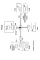
- FIG. 1 is a sequence diagram for explaining the principle of the present invention.
- the present invention includes a method of setting multicast transfer routes for a multicast network including plural nodes each provided with a multicast transfer apparatus, the method including the step of computing multicast transfer routes connecting a given starting point and plural ending points using a multicast transfer route computing apparatus, and the step of setting the computed multicast transfer routes by a multicast route setting apparatus.
- a method of setting multicast transfer routes for a multicast network including plural nodes each provided with a multicast transfer apparatus, the method including the step of computing multicast transfer routes connecting a given starting point and plural ending points using a multicast transfer route computing apparatus, and the step of setting the computed multicast transfer routes by a multicast route setting apparatus.
- the multicast transfer apparatus measures the traffic state of each link in the multicast network, and of each direction in which data flow through the link (step 1).
- the multicast transfer apparatus requests the multicast transfer route computing apparatus to compute multicast transfer routes by transmitting the result of the traffic state measurement thereto (step 2).
- the multicast transfer route computing apparatus computes the shortest route connecting the starting point and the plural ending points based on the result of measurement obtained from the request (step 3) by the multicast transfer apparatus.
- the multicast transfer route computing apparatus computes delay from nodes in the shortest route to the respective ending points (step 4), and stores the computed value in a recording medium (step 5). Then, the multicast transfer route computing apparatus computes the maximum delay of data flowing through the computed shortest route (step 6), and compares the computed maximum delay with a predefined delay condition (step 7). If the computed maximum delay does not satisfy the delay condition, the delay condition is set again.
- a route of which cost between two nodes at both ends is greatest is searched from all partial routes in the computed shortest route (step 8).
- a partial route has the same kind, or different kinds, of the starting point, the ending point, and branching points as both ends, but includes none of the above points in the middle.
- the multicast transfer route computing apparatus removes the searched route from the shortest route (step 9), and divides the multicast transfer route into two route trees (step 10).
- the multicast transfer route computing apparatus sets a route computed separately as a complementary route to the removed route in order to connect the two route trees (step 11), and informs the multicast transfer route setting apparatus of the result of computation (step 12).
- the multicast transfer route setting apparatus sets the multicast transfer route in accordance with the received result of computation (step 13).
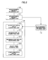
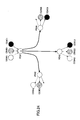
- FIG. 2 is a schematic diagram showing the principle of the present invention.
- the multicast transfer route computing apparatus according to the present invention is provided with the following units: a measurement result receiving unit 130 that receives the result of measurement of traffic state in the multicast network; a measurement information storing unit 112 that stores the received result of measurement; a measurement result storing unit 111 that stores the result of measurement in the measurement information storing unit 112; and a route computing unit 120 that reads the result of measurement from the measurement information storing unit 112, and computes routes based on the result of measurement.
- the route computing unit 120 is further provided with the following units: a shortest route delay computing unit 1211 that computes the shortest routes connecting the starting point and plural ending points, computing at the same time delay from any node on the route to each ending point, and stores the computed value in a recording medium 122; a maximum delay computing unit 1212 that computes the maximum delay of data flowing through the computed shortest route; a maximum cost route searching unit 1213 that compares the maximum delay with a predefined delay condition, sets again the delay condition if the maximum delay does not match the delay condition, and searches a route of which cost between two node on both ends is greatest from all partial routes that include as end points two of the same kind, or different kinds, of the starting point, the ending points, and branching points, and that include none of the above points in the middle; a route tree dividing unit 1214 that removes the searched route from the shortest route and divides the multicast transfer route into two route trees; and a complementary route computing unit 1215 that sets a route computed separately as a complementary route of
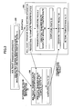
- FIG. 3 is a schematic diagram for explaining the outline of an embodiment of the present invention.
- the numerals in parenthesis in the drawings correspond to those in the following description.
- the present invention relates to a method of setting multicast transfer routes in a multicast network in the case in which there is an upper limit of delay caused from the starting point to the ending point.
- the multicast network includes plural nodes each provided with a multicast transfer apparatus 300, and the multicast transfer route computing apparatus 100 and the multicast transfer route setting apparatus 200 are provided at one of the nodes.
- the multicast transfer apparatus 300 collects network measurement information indicating delay in data transfer, for example, caused by each link in both direction of data flow (1), and informs the multicast transfer route computing apparatus 100 and the multicast transfer route setting apparatus 200 of the network measurement information (2). Then, when a multicast data transfer route needs to be set, the multicast transfer route setting apparatus 200 and the multicast transfer route computing apparatus 100 set the transfer route in accordance with processing to be described below.
- the multicast transfer apparatus 300 collects network measurement information of data transferred between nodes.
- the multicast transfer route computing apparatus 100 computes transfer routes.
- the multicast transfer route setting apparatus 200 sets transfer routes.
- One of the nodes may function as one of the above apparatuses.
- the multicast transfer route setting apparatus 200 requests the multicast transfer route computing apparatus 100 to compute the transfer routes (3).
- the multicast transfer route computing apparatus 100 directs its own route computing module to compute the routes (4). If the multicast transfer route setting apparatus 200 and the multicast transfer route computing apparatus 100 are provided to the same node, the multicast transfer route setting apparatus 200 directs its own route computing module to compute routes (4).
- the transfer route computing module of the multicast transfer route setting apparatus 200 or the multicast transfer route computing apparatus 100 computes the transfer routes based on the collected information (5).
- the route setting module of the multicast transfer route setting apparatus 200 is notified of the computation result (6) and sets the multicast transfer routes in response to receipt of the computation result.
- the network measurement information is collected using extended route computation protocol with which adjacent nodes can exchange the network measurement information.
- the route computation protocol is Open Shortest Path First-Traffic Engineering (OSPF-TE) and Intermediate System-Intermediate System-Traffic Engineering (IS-IS-TE), for example.
- the multicast transfer route computing apparatus 100 is provided with the following: function to receive the network measurement information from the multicast transfer apparatus 300; packet transfer function to transmit the computation result of the transfer routes; computer programs to realize the algorithm of route computation; a recording medium to store the network measurement information, route computation program, and the result of route computation; and function to compute routes.
- the route computation program is provided with the following: function to compute the shortest route from the starting point to the ending points; function to compute the shortest delay from a point of which length is computed in the step of computing the shortest route to the ending point; function to search a route of which cost is the greatest from continuous routes of which both ends are either the starting point, the ending point, or branching points, and that includes none of the above points in the middle; and function to remove the searched route and to select a complementary route, the ending point of which is the ending point of the removed route and the starting point of which is a node included in the shortest partial tree including the starting point of the removed route, and the cost of which is the least.
- the ending point of the complementary route is fixed to the ending point of the removed route. Accordingly, the present invention can create the multicast transfer route without changing the shape of partial tree of which root is the ending point of the removed route.
- the complementary route is selected in accordance with selection criteria that is effective for reducing the cost of the entire tree.
- the cost of route can be effectively reduced in comparison with that of a multicast transfer route computing apparatus that uses the shortest route between the starting point and the ending point as the transfer route.
- the transfer route can be readily computed by using only function to collect the network measurement information indicating the traffic state in an existing network.
- the multicast transfer route computing apparatus 100 can easily obtain the network measurement information.
- new protocol does not need to be developed that collect the network measurement information required for the computation of the transfer route.
- the multicast transfer route computing apparatus 100 and the multicast transfer route setting apparatus 200 that are necessary for realizing the method of setting multicast transfer route according to the present invention are described below.
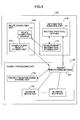
- FIG. 4 is a schematic diagram showing the structure of the multicast transfer route computing apparatus 100 according to an embodiment.
- the multicast transfer route computing apparatus 100 shown in FIG. 4 is provided with the following: an information managing unit 110 that manages the network measurement information related to delay and cost caused by the node and links connecting the nodes in the network; a route computing unit 120 that computes the transfer routes; and a packet processing unit 130 that processes packets to be transmitted and received.
- the packet processing unit 130 of the multicast transfer route computing apparatus 100 receives the network measurement information managed by the information managing unit 110 and the request for computing the route, and transmits the computation result of the transfer route computed by the route computing unit 120 to the multicast transfer route setting apparatus 200.
- the information managing unit 110 is provided with a routing protocol module 111 that processes protocols and a measurement information storing unit 112 that manages the network measurement information such as network topology, delay, and cost measured by the protocol.
- the route computing unit 120 is provided with a route computing module 121 that computes the transfer route, and a computation result storing unit 122 that stores the computation result.
- the packet processing unit 130 is provided with the following: a packet processing module 131 that determines the kind of received packet and transfers, or transmits, to the information managing unit 110, the received packet; a packet transfer table storing unit 132 that stores the destinations of packets; and one or more network interfaces 133.
- FIG. 5 is a schematic diagram showing the structure of the multicast transfer route setting unit 200 according to an embodiment.
- the multicast transfer route setting unit 200 is provided with the following: an information managing unit 210 that manages information related to the delay and cost caused by the nodes and links in the network; a measuring unit 220 that measures delay and cost caused by the multicast transfer route setting apparatus 200; a route setting protocol processing unit 230 that sets the route when a new data flow is generated; a packet processing unit 240 that processes received packets.
- the basic structure of the information managing unit 210 is similar to the information managing unit 110 of the multicast transfer route computing apparatus 100.
- the information managing unit 210 is provided with a routing protocol module 211 and a measurement information storing unit 212.
- the measuring unit 220 is provided with a measurement module that measures information such as the state of network interfaces 243 (to be described below) provided in the packet processing unit 240 and delay in processing by each node of the network.
- the packet processing unit 240 is provided with the following: a packet processing module 241 that determines the kind of received packets, transfers the packets, and determines the setting of new routes; a packet transfer table storing unit 242 that stores the destination to which the packets are transferred, and network interfaces 243.
- the multicast transfer route setting apparatus 200 is provided with a route computing unit 250, which includes a computation processing module 251 that computes transfer routes and a computation result storing unit 252 that stores the computation result. If the multicast transfer route setting apparatus 200 computes the transfer routes, then the route computing unit 250 operates in the same manner as the multicast transfer route computing apparatus 100.
- the route setting protocol processing unit 230 receives a request from the packet processing unit 240 for setting a route, and transmits the request for setting a route to the multicast transfer route computing apparatus 100.
- the route setting protocol processing unit 230 sets a transfer route for data transfer in accordance with the computation result of the transfer route received from the multicast transfer route computing apparatus 100.
- the node has the above units provided to the multicast transfer route computing apparatus 100 and the multicast transfer route setting apparatus 200, and performs the above steps. If the multicast transfer apparatus 300 is provided to the same node, the route setting protocol processing unit 230 requests an adjacent node to compute the route.
- the operation of the multicast transfer route computing apparatus 100, the multicast transfer route setting apparatus 200, and the multicast transfer apparatus 300 is described below.
- the nodes that function as multicast transfer apparatuses 300 always exchange the network measurement information indicating the network topology, delay, and cost. Each node stores the network measurement information obtained by the exchange.
- the network measurement information exchanged by the nodes includes not only the network measurement information measured by an adjacent node but also the stored network measurement information measured by other nodes. Each node retains the network measurement information such as the network topology and delay of all nodes in the network by exchanging the network measurement information.
- a node that functions as the multicast transfer route setting apparatus 200 requests another node that functions as the multicast transfer route computing apparatus 100 to compute the transfer routes.
- the node that functions as the multicast transfer route computing apparatus 100 computes the transfer route based on the network measurement information related to the traffic in the network such as the topology and the delay managed by the information managing unit 110 and on information about the ending points received from the requesting node.
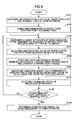
- FIG. 6 is a flowchart showing an algorithm of computing transfer routes according to an embodiment.
- the multicast transfer route computing apparatus 100 receives a request for computing a route from a node having a function of the multicast transfer route setting apparatus 200.
- the multicast transfer route computing apparatus 100 also receives information related to the ending points of the data transfer from the multicast transfer route setting apparatus 200.
- the route computing unit 120 of the multicast transfer route computing apparatus 100 reads the network measurement information indicating the network topology and the traffic state stored in the measurement information storing unit 112 (database) of the information managing unit 110 (step 101).
- the route computing module 121 computes a route (least delay route) that causes the least delay from the starting point to the ending point using the network measurement information (step 102).
- the route computing module 121 computes the least delay route from the node that has transmitted the request to the ending node.
- the Dijkstra's algorithm can be used for the computation of the least delay route. According to the above arrangement, the least delay route from the node that has transmitted the request to the ending points can be computed.
- the route computing module 121 of the multicast transfer route computing apparatus 100 searches partial routes starting and ending with one of the starting point, the ending points, and branching points, and at the same time not including any one of the above points in the middle, the partial routes included in the least delay routes computed in step 102 (step 103).
- the partial route of which cost is the greatest is selected from the computed partial routes, and it is removed from the least delay route described above.
- Information about the ending points of the removed partial route is stored in the computation result storing unit (step 104).
- the least delay route is divided into two partial routes.
- the route computing module 121 of the multicast transfer route computing apparatus 100 adds the following to the network topology stored in the measurement information storing unit 112 of the information management unit 110: a pseudo starting point, and links connecting the pseudo starting point and respective ones of all nodes included in the remaining partial route including the starting point.
- the following are removed from the network topology: links and nodes through which the remaining partial route not including the starting point, and links connected to the nodes.
- the following are not removed from the network topology: the node that becomes the starting point of the partial route to be removed, and the links connecting the node and other nodes that do not constitute the partial route. (step 105)
- a route connecting the pseudo starting point and a starting point of the remaining partial route that does not include the starting point of the least delay route is searched.
- an algorithm called "k-th shortest path algorithm” may be used that computes a route of which delay is the k-th least. This type of algorithm searches a route with the "k-1"-th least delay, and then searches a route with the "k"-th least delay. It is possible to set an upper limit to the delay and to perform this algorithm until all routes with lower delay are found.
- the searched routes become candidates of a complementary route that complement the removed route (step 106).
- the route computing module 121 of the multicast transfer route computing apparatus 100 computes the total cost of the routes searched by the k-th shortest path algorithm, and selects the route with the least cost. The selected route becomes the complementary route that complements the removed route (step 107).
- the route computing module 121 of the multicast transfer route computing apparatus 100 determines whether the route to be removed and the selected complementary route are the same. If they are the same route, the route computing module 121 searches a route with the next least cost, and repeats the above step until the complementary route becomes the searched route (step 108) .
- the route computing module 121 returns the result of computation to the requesting node that has requested to compute the route (step 109).
- the multicast transfer apparatus 300 may use OSPF-TE for collecting the network measurement information such as delay.
- the OSPF-TE is a communication protocol in which the traffic information of the network such as delay is stored in the topology information exchange information of OSPF, or the routing protocol of unicast.
- multicast MPLS Multi Protocol Label Switching
- RSVP-TE Resource Reservation Protocol-Traffic Engineering
- the multicast MPLS is different from the RSVP-TE used in an ordinary MPLS in that an information element in which a tree topology can be stored is added to a message for generating LSP (Label Switched Path), and Point-to-Multipoint LSP can be established.
- LSP Label Switched Path
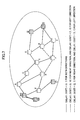
- FIG. 7 is a network diagram showing an embodiment of the present invention.
- the multicast network includes the multicast transfer route setting apparatus 200, the nodes A-I, and the ending points (1)-(3) connected by communication cable (links).
- Each link has two properties, delay and cost. The delay property and cost property of a link may depend on the direction in which data are transmitted. In the case of FIG.
- the multicast transfer route setting apparatus 200 transfers data to the ending points (1)-(3) based on the result of computation by the multicast transfer route computing apparatus 100.
- Each node collects the network measurement information indicating the delay caused by the links using the above OSPF-TE.
- the network measurement information is informed to the multicast transfer route computing apparatus 100 in advance.
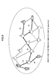
- FIG. 8 shows the least delay routes from the starting point to the respective ending points.
- the multicast transfer route computing apparatus 100 computes the least delay routes from the multicast transfer route setting apparatus 200, which becomes the starting point, to the respective ending points (1)-(3).
- the multicast transfer route computing apparatus 100 uses the Dijkstra's algorithm for computing the least delay routes.
- the Dijkstra's algorithm is well known in the art as an algorithm for computing the least delay route.
- the least cost routes computed by the multicast transfer route computing apparatus 100 are as follows:
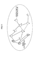
- FIG. 9 is a network diagram showing the computation of a route to be removed according to an embodiment.
- the least delay route is divided into partial routes, and the partial routes of which ends are either the starting point, the ending point, or a branching point, and that include none of the above points in the middle.
- the following partial routes are searched:
- the complementary route is a route that starts with one of the points included in the partial route 40, ends with the ending point of the removed partial route (the starting point of the partial route 50), does not intersect the partial route 50, and of which total cost is the least.
- the method of computation is described below.
- the network topology used for the computation is different from that of the network for which the complementary route is computed as follows.
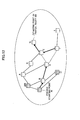
- a pseudo starting point 70 is provided, and links from the pseudo starting point 70 to all nodes included in the partial route 40 are added. Subsequently, the links and nodes (excluding the starting point G of the partial route 50) included in the partial route 50 and the other links connected to the nodes are removed. As a result, the network topology becomes as shown in FIG. 11.
- a route connecting the pseudo starting point 70 and the starting point G of the partial route 50 is computed using the k-th shortest path algorithm.
- the k-th shortest path algorithm is an algorithm for searching the k-th shortest path, which has been proposed and is known in the art.
- the k-th shortest path algorithm may be applied to the properties such as the delay and cost.
- the k-th shortest path algorithm is recursively applied while the delay is below the upper limit. That is, after computing the "k-1"-st shortest path, using the result of the previous computation, the k-th shortest path is computed.
- the partial route of which the total cost property is the least is selected as the complementary route.
- the computation of the route with the k-th least cost is terminated.
- the route computed at that time except for the pseudo starting point 70 is selected as the complementary route.
- FIG. 12 shows the result of the computation.
- the route connecting the pseudo starting point 70 and the node G, which is the starting point of the partial route 50, with the least cost is: pseudo starting point 70 - node B - node D - node F - node E - node G. Therefore, since the pseudo starting point 70 is excluded, the following route is selected as the complementary route: node B - node D - node F - node E - node G.
- the delay incurred between the node G, which is the starting point G of the partial route 50, and the ending points located in the downstream side of the node G is used for the comparison with the upper limit of delay.
- the topology of the partial route 50 changes.
- this step is omitted, and thus the computation time can be reduced.
- the maximum delay is evaluated, and the maximum delay incurred by the route to which the complementary route is connected between the starting point and the ending points is found to be 7 that is incurred on the route connecting the starting point 200 and the ending point (3).
- the tolerable upper limit of delay is 7, which is satisfied in this case.
- the route that satisfies the above delay condition is selected as the complementary route, which is used to connect the partial route 40 and the partial route 50.
- a condition that terminates the algorithm is described below. If the complementary route is the same as the removed route, or the delay of the complementary route is greater than that of the removed route, the removed route is selected as the complementary route, and then the algorithm terminates. If the complementary route is not the same as the removed route, the complementary route is marked, and the following route is selected, and removed: a route (i) of which both ends are either the starting point, the ending points, or the branching points, (ii) that include none of the starting point, the ending points, and the branching points in the middle, and (iii) of which cost is the greatest besides the marked route. Then, the complementary route is searched. The above step is repeated until all the routes are marked. As a result, the computation result shown in FIG. 13 is obtained.
- the multicast transfer route computing apparatus and the multicast transfer route setting apparatus described above may be provided with computer systems therein.
- the above steps may be stored in a computer readable recording medium in the form of computer programs.
- the computer readable recording medium are: a magnetic disk, a magneto-optical disk, a CD-ROM, a DVD-ROM, and a semiconductor memory.
- the computer program may be delivered to a computer via a communication channel, and the computer that receives the computer program may execute the computer program.
- the computer program may be stored in a hard disk or a removable recording medium such as a flexible disk or a CD-ROM that are connected to the computer that operates as the multicast transfer route computing apparatus, and the computer program may be installed into a CPU when the present invention is embodied.
- a system has a node to which an algorithm for computing the route is provided, taking into consideration the upper limit of delay incurred between the starting point and the ending points.
- the system can provide application in which there is an upper limit in delay incurred between the starting point and the ending points in a multicast communication satisfying the delay condition but reducing the cost of the entire route.
- the method according to the present invention requires shorter time for computing the route than the conventional method, the method according to the present invention can reduce time required for providing the service. According to this arrangement, the user can be provided with the service quickly.
- the multicast distribution (transfer) in accordance with the multicast communication route setting technique can be realized by a network using a multicast label switching method.
- a preferred embodiment of the multicast label switching method according to the present invention is described below with reference to the drawings.
- a method of setting a communication route using the multicast label switching and a mechanism for transferring packets are described first.
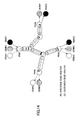
- FIG. 14 shows the pattern of optimum multicast distribution between provider edge (PE) routers in which connection VPN sites (CE) according to an embodiment of the present invention are taken into consideration.
- the exemplary provider network shown in FIG. 14 is provided with provider edge routers PE#1, PE#2, PE#3, and PE#4, and provider (P) routers connecting the PE routers.
- PE#1 accommodates CE#A1 belonging to VPN#A, CE#B1 belonging to VPN#B, and CE#C1 belonging to VPN#C.
- PE#2 accommodates CE#A2 belonging to VPN#A and CD#B2 belonging to VPN#B.
- PE#3 accommodates CE#A3 belonging to VPN#A, CE#B3 belonging to VPN#B, and CE#C3 belonging to VPN#C.
- PE#4 accommodates CE#B4 belonging to VPN#B and CE#C4 belonging to VPN#C.
- LSP point-to-multi point label switched paths
- Paths indicated as pipes shown in FIG. 14 correspond to LSPs.
- the sites of VPN#A are accommodated under PE#2 and PE#3, it is desired to set multicast sub-label switching routes in which PE#1 is a source and PE#2 and #3 are leafs.
- the multicast distribution route indicated by the arrows of the dotted line correspond to this multicast sub-label switching route.
- the arrows of the short and long dash line correspond to VPN#B
- the arrows of the solid line correspond to VPN#C.
- the second layer of the label switching path is a subset of the first layer of the label switching path.
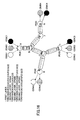
- FIG. 15 shows a signaling mechanism for setting multicast label switching path shown in FIG. 14.
- the multicast label signaling is set by extending the conventional RSVP-TE (Resource Reservation Protocol-Traffic Engineering) mechanism into multicast.
- RSVP-TE Resource Reservation Protocol-Traffic Engineering
- the multicast distribution circuit to be set is defined by TERO (Tree Explicit Route Object) of path message.
- TERO Transmission Explicit Route Object
- TERO indicating the set routes of the multicast label switching path is prepared for the two layers.
- multicast label switching routes connecting the first layer of PE#1 (A) to PE#2 (D), PE#3 (E), and PE#4 (G) are defined.
- the TERO is defined as [A(0), B(1), C(2), D(3), E(3), F(2), G(3)] . This definition is based on a Depth First Order algorithm. Numerals in parenthesis associated with each node indicate the distances (the number of hops) from the source node PE#1 (A).
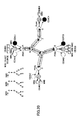
- the example shown in FIG. 15 is the multicast distribution routes of which connection is configured as shown in FIG. 17. Since the Depth First Order algorithm designates the path in the direction of depth at first, the TERO is designated as [A(0), B(1), C(2), D(3), E(3), F(2), G(3)]. Additionally, a multicast LSP is set for each VPN under the first layer of the multicast LSP.
- the Path message is transferred to leaf nodes in accordance with TERO information.
- layered labels are assigned by Resv message from downstream.
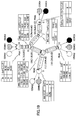
- FIG. 19 shows label conversion tables set to respective nodes by the above operation and hierarchical labels used by the respective links. For example, because the TERO of the second layer including the VPN#A, B, and C arrive at the node PE#3 (E), the labels A(101, 30), B(101, 25), and C(101, 5) are assigned to respective VPNs.
- FIG. 20 shows the case in which there are multicast source M#A, M#B, and M#C in the VPN#B under the PE#1, the distribution patterns (shown in the upper left portion of FIG. 20) of which are different from each other.
- M#A, M#B, and M#C are distributed to all PE routers PE#2, PE#3, and PE#4 in which VPN#B is accommodated.
- the efficiency of the network becomes not high.
- M#A is multicast-distributed to PE#4 that does not receive it.
- this label corresponds to a multicast source group having the same distribution topology in the same VPN site.
- Any distribution pattern can be realized by using such a heuristic stratifying mechanism.
- the three layered label switching technique described in the above embodiment is effective for distributing the multicast traffic in the VPN via the optimum topology.
- the information of multicast distribution routes accommodated in each VPN needs to be exchanged between the PE routers in the same manner as the ordinary unicast route exchange.
- FIG. 21 An example is shown in FIG. 21.
- the information can be exchanged in accordance with MP-BGP defined as rfc2547bis.
- FIG. 21 shows an example in which the PE routers other than PE1 distributes to PE1 the multicast distribution routes in the VPN sites accommodated in the PE routers.
- PE#4 accommodates VPN#A and B
- PE#4 distributes the multicast route MG# ⁇ of VPN#A and the multicast route MG# ⁇ of VPN#B to PE1 using the MP-BGP.
- one directional exchange of the routes is shown.
- the bi-directional full-mesh exchange of routes among PE routers allows each PE router to have the information about all the multicast routes in the VPN sites accommodated by opposing PE routers.
- the transmission node that sets the multicast label switching routes can set the hierarchical point-to-multipoint LSP in which the multicast routes of opposing PEs are taken into account.
- FIG. 22 shows a VPN model to which the present invention is applied. The application of this model makes the multicast of PIM-SM of VPN site animation possible to be VPN-transferred.
- a method of multicast label switching and a method of VPN multicast label switching of the present invention it is possible to build a multicast transfer network and a VPN network that can multicast-distribute using the topology suitable for the destination receiving group and at the same time to prevent the transfer cost of the entire multicast distribution routes.
- the multicast distribution network becomes efficient and of high performance.
Applications Claiming Priority (5)
| Application Number | Priority Date | Filing Date | Title |
|---|---|---|---|
| JP2003031605 | 2003-02-07 | ||
| JP2003031605 | 2003-02-07 | ||
| JP2003038782 | 2003-02-17 | ||
| JP2003038782 | 2003-02-17 | ||
| PCT/JP2004/001246 WO2004071032A1 (fr) | 2003-02-07 | 2004-02-06 | Procede d'etablissement d'itineraire de transfert multidiffusion, et procede de commutation d'etiquette multidiffusion permettant de mettre en oeuvre le procede susmentionne |
Publications (2)
| Publication Number | Publication Date |
|---|---|
| EP1592183A1 true EP1592183A1 (fr) | 2005-11-02 |
| EP1592183A4 EP1592183A4 (fr) | 2010-02-24 |
Family
ID=32852693
Family Applications (1)
| Application Number | Title | Priority Date | Filing Date |
|---|---|---|---|
| EP20040708880 Withdrawn EP1592183A4 (fr) | 2003-02-07 | 2004-02-06 | Procede d'etablissement d'itineraire de transfert multidiffusion, et procede de commutation d'etiquette multidiffusion permettant de mettre en oeuvre le procede susmentionne |
Country Status (4)
| Country | Link |
|---|---|
| US (2) | US7583601B2 (fr) |
| EP (1) | EP1592183A4 (fr) |
| JP (1) | JP3900195B2 (fr) |
| WO (1) | WO2004071032A1 (fr) |
Cited By (4)
| Publication number | Priority date | Publication date | Assignee | Title |
|---|---|---|---|---|
| WO2007143929A1 (fr) | 2006-06-09 | 2007-12-21 | Huawei Technologies Co., Ltd. | Procédé, système et appareil d'affectation d'étiquettes |
| WO2008125144A1 (fr) * | 2007-04-13 | 2008-10-23 | Telefonaktiebolaget Lm Ericsson (Publ) | Construction d'un arbre recouvrant sur ethernet |
| CN101292467B (zh) * | 2005-10-19 | 2010-09-22 | 微软公司 | 用于多方音频视频会议的应用级路由协议的方法和设备 |
| EP2624506A4 (fr) * | 2010-09-30 | 2015-07-22 | Zte Corp | Procédé et système de commande de chemin et appareil calcul de chemin |
Families Citing this family (75)
| Publication number | Priority date | Publication date | Assignee | Title |
|---|---|---|---|---|
| US7769873B1 (en) | 2002-10-25 | 2010-08-03 | Juniper Networks, Inc. | Dynamically inserting filters into forwarding paths of a network device |
| US8078758B1 (en) | 2003-06-05 | 2011-12-13 | Juniper Networks, Inc. | Automatic configuration of source address filters within a network device |
| US7925778B1 (en) * | 2004-02-13 | 2011-04-12 | Cisco Technology, Inc. | Method and apparatus for providing multicast messages across a data communication network |
| US7856509B1 (en) | 2004-04-09 | 2010-12-21 | Juniper Networks, Inc. | Transparently providing layer two (L2) services across intermediate computer networks |
| JP2006060579A (ja) * | 2004-08-20 | 2006-03-02 | Fujitsu Ltd | アプリケーション特性に応じて複数の経路を同時に利用する通信装置 |
| US7570604B1 (en) | 2004-08-30 | 2009-08-04 | Juniper Networks, Inc. | Multicast data trees for virtual private local area network (LAN) service multicast |
| US8619774B2 (en) * | 2004-10-26 | 2013-12-31 | Cisco Technology, Inc. | Method and apparatus for providing multicast messages within a virtual private network across a data communication network |
| US7602702B1 (en) | 2005-02-10 | 2009-10-13 | Juniper Networks, Inc | Fast reroute of traffic associated with a point to multi-point network tunnel |
| US7570649B2 (en) * | 2005-02-28 | 2009-08-04 | Alcatel Lucent | Forwarding state sharing between multiple traffic paths in a communication network |
| US8089964B2 (en) | 2005-04-05 | 2012-01-03 | Cisco Technology, Inc. | Transporting multicast over MPLS backbone using virtual interfaces to perform reverse-path forwarding checks |
| CN100531117C (zh) * | 2005-06-04 | 2009-08-19 | 华为技术有限公司 | 一种自动交换光网络信息传输方法 |
| US9166807B2 (en) * | 2005-07-28 | 2015-10-20 | Juniper Networks, Inc. | Transmission of layer two (L2) multicast traffic over multi-protocol label switching networks |
| US7990965B1 (en) | 2005-07-28 | 2011-08-02 | Juniper Networks, Inc. | Transmission of layer two (L2) multicast traffic over multi-protocol label switching networks |
| JP4375303B2 (ja) * | 2005-08-19 | 2009-12-02 | ブラザー工業株式会社 | 情報通信システム、情報通信方法、情報通信システムに含まれるノード装置、情報処理プログラムおよびノード装置のプログラム |
| US7564803B1 (en) | 2005-08-29 | 2009-07-21 | Juniper Networks, Inc. | Point to multi-point label switched paths with label distribution protocol |
| JP4577163B2 (ja) * | 2005-09-06 | 2010-11-10 | 株式会社日立製作所 | インターワーキング方法及び装置 |
| US7852841B2 (en) * | 2005-11-04 | 2010-12-14 | Cisco Technology, Inc. | In-band multicast signaling using LDP |
| US8107473B2 (en) * | 2006-03-16 | 2012-01-31 | Cisco Technology, Inc. | Automation fallback to P2P LSPs for mLDP built multipoint-trees |
| CN100563203C (zh) * | 2005-11-11 | 2009-11-25 | 华为技术有限公司 | 通信网络中组播树叶子节点网元信号传送的方法 |
| KR100949323B1 (ko) * | 2005-11-25 | 2010-03-23 | 지티이 코포레이션 | 자동 교환 광 네트워크 멀티캐스트 서비스의 루트 선택방법 |
| JP4881610B2 (ja) * | 2005-11-30 | 2012-02-22 | 株式会社日立製作所 | 測定システム及び管理装置及びその処理分散方法 |
| US8270395B2 (en) * | 2006-01-30 | 2012-09-18 | Juniper Networks, Inc. | Forming multicast distribution structures using exchanged multicast optimization data |
| US7839850B2 (en) | 2006-01-30 | 2010-11-23 | Juniper Networks, Inc. | Forming equal cost multipath multicast distribution structures |
| US8560651B2 (en) * | 2006-03-07 | 2013-10-15 | Cisco Technology, Inc. | Method and system for streaming user-customized information |
| US8934486B2 (en) * | 2006-03-16 | 2015-01-13 | Cisco Technology, Inc. | System and method for implementing multicast over a label-switched core network |
| US7839862B1 (en) | 2006-06-30 | 2010-11-23 | Juniper Networks, Inc. | Upstream label assignment for the label distribution protocol |
| US7787380B1 (en) | 2006-06-30 | 2010-08-31 | Juniper Networks, Inc. | Resource reservation protocol with traffic engineering point to multi-point label switched path hierarchy |
| US7742482B1 (en) | 2006-06-30 | 2010-06-22 | Juniper Networks, Inc. | Upstream label assignment for the resource reservation protocol with traffic engineering |
| US7856014B2 (en) * | 2006-10-27 | 2010-12-21 | International Business Machines Corporation | High capacity multicast forwarding |
| US8045562B2 (en) * | 2006-10-31 | 2011-10-25 | Hewlett-Packard Development Company, L.P. | Estimating link interference and bandwidth |
| US8279753B2 (en) * | 2007-01-11 | 2012-10-02 | Oracle International Corporation | Efficient determination of fast routes when voluminous data is to be sent from a single node to many destination nodes via other intermediate nodes |
| JP4825696B2 (ja) * | 2007-01-22 | 2011-11-30 | アラクサラネットワークス株式会社 | パケット中継装置 |
| US8432894B2 (en) * | 2007-02-27 | 2013-04-30 | Alcatel Lucent | Asymmetrical forwarding in layer 3 IP VPNs |
| US7986692B2 (en) * | 2007-03-08 | 2011-07-26 | Motorola Solutions, Inc. | System and method for transmitting call information in a communication system with long link delays |
| KR101334459B1 (ko) * | 2007-06-28 | 2013-11-29 | 주식회사 케이티 | 멀티캐스트 vpn망에서의 mdt 시험 시스템 및 그 방법 |
| US8125926B1 (en) | 2007-10-16 | 2012-02-28 | Juniper Networks, Inc. | Inter-autonomous system (AS) virtual private local area network service (VPLS) |
| US8289883B2 (en) * | 2007-12-21 | 2012-10-16 | Samsung Electronics Co., Ltd. | Hybrid multicast routing protocol for wireless mesh networks |
| TWI350672B (en) * | 2007-12-31 | 2011-10-11 | Nat Univ Tsing Hua | A matjod for constructing network application-layer multicast trees by transmiting data among network terminal equipments |
| US7936780B1 (en) | 2008-03-12 | 2011-05-03 | Juniper Networks, Inc. | Hierarchical label distribution protocol for computer networks |
| JP5112229B2 (ja) * | 2008-09-05 | 2013-01-09 | 株式会社エヌ・ティ・ティ・ドコモ | 配信装置、端末装置及びシステム並びに方法 |
| JP5080406B2 (ja) * | 2008-09-05 | 2012-11-21 | 株式会社エヌ・ティ・ティ・ドコモ | 配信装置、端末装置及びシステム並びに方法 |
| US8289978B2 (en) * | 2008-10-15 | 2012-10-16 | At&T Intellectual Property I, Lp | Broadcast interactive television system |
| US7929557B2 (en) | 2008-11-14 | 2011-04-19 | Juniper Networks, Inc. | Summarization and longest-prefix match within MPLS networks |
| US8077726B1 (en) | 2008-12-10 | 2011-12-13 | Juniper Networks, Inc. | Fast reroute for multiple label switched paths sharing a single interface |
| US8391303B2 (en) * | 2009-04-16 | 2013-03-05 | Futurewei Technologies, Inc. | Border gateway protocol (BGP) grouped route withdrawals |
| CN102098591B (zh) * | 2009-12-11 | 2013-08-21 | 中兴通讯股份有限公司 | 一种ason中资源共享的方法和业务节点 |
| US20110188499A1 (en) * | 2010-02-04 | 2011-08-04 | Cisco Technology, Inc. | Point-to-multipoint path implementation in a multicast virtual private network |
| US8422514B1 (en) | 2010-02-09 | 2013-04-16 | Juniper Networks, Inc. | Dynamic configuration of cross-domain pseudowires |
| US8310957B1 (en) | 2010-03-09 | 2012-11-13 | Juniper Networks, Inc. | Minimum-cost spanning trees of unicast tunnels for multicast distribution |
| US8842679B2 (en) | 2010-07-06 | 2014-09-23 | Nicira, Inc. | Control system that elects a master controller instance for switching elements |
| US9680750B2 (en) | 2010-07-06 | 2017-06-13 | Nicira, Inc. | Use of tunnels to hide network addresses |
| US8964528B2 (en) | 2010-07-06 | 2015-02-24 | Nicira, Inc. | Method and apparatus for robust packet distribution among hierarchical managed switching elements |
| US9246838B1 (en) | 2011-05-27 | 2016-01-26 | Juniper Networks, Inc. | Label switched path setup using fast reroute bypass tunnel |
| US9100213B1 (en) | 2011-06-08 | 2015-08-04 | Juniper Networks, Inc. | Synchronizing VPLS gateway MAC addresses |
| EP2710766B1 (fr) * | 2011-06-22 | 2016-01-13 | Huawei Technologies Co., Ltd. | Diffusion groupée indépendante du protocole avec prise en charge de qualité de service |
| WO2013139524A1 (fr) * | 2012-03-19 | 2013-09-26 | Nokia Siemens Networks Oy | Mécanisme de transmission de données avec robustesse améliorée à l'aide de connexions multiflux |
| US8837479B1 (en) | 2012-06-27 | 2014-09-16 | Juniper Networks, Inc. | Fast reroute between redundant multicast streams |
| JP6113443B2 (ja) * | 2012-09-14 | 2017-04-12 | 株式会社日立国際電気 | 通信システム及びその通信方法 |
| US9049148B1 (en) | 2012-09-28 | 2015-06-02 | Juniper Networks, Inc. | Dynamic forwarding plane reconfiguration in a network device |
| US20140204763A1 (en) * | 2013-01-24 | 2014-07-24 | Aruba Networks, Inc. | Method and System for Routing Data |
| US8953500B1 (en) | 2013-03-29 | 2015-02-10 | Juniper Networks, Inc. | Branch node-initiated point to multi-point label switched path signaling with centralized path computation |
| CN103248571A (zh) * | 2013-05-16 | 2013-08-14 | 湖北邮电规划设计有限公司 | 一种最优第二路由的计算方法 |
| US9432204B2 (en) | 2013-08-24 | 2016-08-30 | Nicira, Inc. | Distributed multicast by endpoints |
| US9602385B2 (en) | 2013-12-18 | 2017-03-21 | Nicira, Inc. | Connectivity segment selection |
| US9602392B2 (en) | 2013-12-18 | 2017-03-21 | Nicira, Inc. | Connectivity segment coloring |
| CN103795626B (zh) * | 2014-02-19 | 2017-07-07 | 华为技术有限公司 | 组播快速保护倒换的方法与装置 |
| US9794079B2 (en) | 2014-03-31 | 2017-10-17 | Nicira, Inc. | Replicating broadcast, unknown-unicast, and multicast traffic in overlay logical networks bridged with physical networks |
| US9806895B1 (en) | 2015-02-27 | 2017-10-31 | Juniper Networks, Inc. | Fast reroute of redundant multicast streams |
| CN105871723A (zh) * | 2015-12-14 | 2016-08-17 | 乐视云计算有限公司 | 数据传输方法、装置及系统 |
| WO2019069353A1 (fr) * | 2017-10-02 | 2019-04-11 | 三菱電機株式会社 | Dipositif de communication et réseau de communication |
| US11218415B2 (en) * | 2018-11-18 | 2022-01-04 | Mellanox Technologies Tlv Ltd. | Low-latency processing of multicast packets |
| KR102291440B1 (ko) * | 2019-04-04 | 2021-08-18 | 주식회사 케이티 | 회선 개통 자동화 방법 및 그 장치 |
| US10778457B1 (en) | 2019-06-18 | 2020-09-15 | Vmware, Inc. | Traffic replication in overlay networks spanning multiple sites |
| CN113472671B (zh) * | 2020-03-30 | 2023-05-02 | 中国电信股份有限公司 | 组播路由的确定方法、装置和计算机可读存储介质 |
| US11784922B2 (en) | 2021-07-03 | 2023-10-10 | Vmware, Inc. | Scalable overlay multicast routing in multi-tier edge gateways |
Citations (1)
| Publication number | Priority date | Publication date | Assignee | Title |
|---|---|---|---|---|
| US20030012216A1 (en) * | 2001-07-16 | 2003-01-16 | Ibm Corporation | Methods and arrangements for building a subsource address multicast distribution tree using network bandwidth estimates |
Family Cites Families (8)
| Publication number | Priority date | Publication date | Assignee | Title |
|---|---|---|---|---|
| JP3614059B2 (ja) | 1999-11-30 | 2005-01-26 | 日本電気株式会社 | 通信コネクションマージ方法及びそれを用いるノード |
| US6947434B2 (en) * | 2000-11-16 | 2005-09-20 | Telefonaktiebolaget Lm Ericsson (Publ) | Subgroup multicasting in a communications network |
| JP2002176441A (ja) | 2000-12-08 | 2002-06-21 | Fujitsu Ltd | 通信装置 |
| JP2002271356A (ja) * | 2001-03-12 | 2002-09-20 | Oki Electric Ind Co Ltd | ネットワーク通信システム |
| JP2002300169A (ja) * | 2001-03-29 | 2002-10-11 | Mitsubishi Electric Corp | 無線通信装置およびパスルーティング方法 |
| EP1515495B1 (fr) * | 2002-12-11 | 2008-04-02 | Nippon Telegraph and Telephone Corporation | Procédé et dispositif de calculation de chemins de multidiffusion |
| US7660254B2 (en) * | 2006-12-22 | 2010-02-09 | Cisco Technology, Inc. | Optimization of distributed tunnel rerouting in a computer network with coordinated head-end node path computation |
| US7668971B2 (en) * | 2008-01-11 | 2010-02-23 | Cisco Technology, Inc. | Dynamic path computation element load balancing with backup path computation elements |
-
2004
- 2004-02-06 US US10/522,713 patent/US7583601B2/en not_active Expired - Fee Related
- 2004-02-06 EP EP20040708880 patent/EP1592183A4/fr not_active Withdrawn
- 2004-02-06 WO PCT/JP2004/001246 patent/WO2004071032A1/fr active Application Filing
- 2004-02-06 JP JP2005504888A patent/JP3900195B2/ja not_active Expired - Fee Related
-
2008
- 2008-09-25 US US12/237,912 patent/US7792099B2/en not_active Expired - Fee Related
Patent Citations (1)
| Publication number | Priority date | Publication date | Assignee | Title |
|---|---|---|---|---|
| US20030012216A1 (en) * | 2001-07-16 | 2003-01-16 | Ibm Corporation | Methods and arrangements for building a subsource address multicast distribution tree using network bandwidth estimates |
Non-Patent Citations (3)
| Title |
|---|
| GEORGE N ROUSKAS ET AL: "Multicast Routing with End-to-End Delay and Delay Variation Constraints" IEEE JOURNAL ON SELECTED AREAS IN COMMUNICATIONS, IEEE SERVICE CENTER, PISCATAWAY, US, vol. 15, no. 3, 1 April 1997 (1997-04-01), XP011054626 ISSN: 0733-8716 * |
| LOW C P: "Loop-free multicast routing with end-to-end delay constraint" COMPUTER COMMUNICATIONS, ELSEVIER SCIENCE PUBLISHERS BV, AMSTERDAM, NL, vol. 22, no. 2, 25 January 1999 (1999-01-25), pages 181-192, XP004157085 ISSN: 0140-3664 * |
| See also references of WO2004071032A1 * |
Cited By (6)
| Publication number | Priority date | Publication date | Assignee | Title |
|---|---|---|---|---|
| CN101292467B (zh) * | 2005-10-19 | 2010-09-22 | 微软公司 | 用于多方音频视频会议的应用级路由协议的方法和设备 |
| WO2007143929A1 (fr) | 2006-06-09 | 2007-12-21 | Huawei Technologies Co., Ltd. | Procédé, système et appareil d'affectation d'étiquettes |
| EP2028789A1 (fr) * | 2006-06-09 | 2009-02-25 | Huawei Technologies Co Ltd | Procédé, système et appareil d'affectation d'étiquettes |
| EP2028789A4 (fr) * | 2006-06-09 | 2009-10-21 | Huawei Tech Co Ltd | Procédé, système et appareil d'affectation d'étiquettes |
| WO2008125144A1 (fr) * | 2007-04-13 | 2008-10-23 | Telefonaktiebolaget Lm Ericsson (Publ) | Construction d'un arbre recouvrant sur ethernet |
| EP2624506A4 (fr) * | 2010-09-30 | 2015-07-22 | Zte Corp | Procédé et système de commande de chemin et appareil calcul de chemin |
Also Published As
| Publication number | Publication date |
|---|---|
| US20090028149A1 (en) | 2009-01-29 |
| WO2004071032A1 (fr) | 2004-08-19 |
| JP3900195B2 (ja) | 2007-04-04 |
| US7792099B2 (en) | 2010-09-07 |
| EP1592183A4 (fr) | 2010-02-24 |
| US20060147204A1 (en) | 2006-07-06 |
| US7583601B2 (en) | 2009-09-01 |
| JPWO2004071032A1 (ja) | 2006-06-01 |
Similar Documents
| Publication | Publication Date | Title |
|---|---|---|
| US7583601B2 (en) | Multicast transfer route setting method, and multicast label switching method for implementing former method | |
| EP1395003B1 (fr) | Procédé de routage selon le plus court chemin à base de contraintes pour des réseaux optiques de transport commutés dynamiquement | |
| US7570649B2 (en) | Forwarding state sharing between multiple traffic paths in a communication network | |
| CN105049350B (zh) | 利用出口对等工程的分段路由的方法、装置及系统 | |
| USRE47260E1 (en) | System and method for point to multipoint inter-domain MPLS traffic engineering path calculation | |
| US9363161B2 (en) | Virtual connection route selection apparatus and techniques | |
| JP4612987B2 (ja) | マルチプロトコルラベルスイッチングベースのポイント対マルチポイント・トラフィックルーチング方法 | |
| US7948996B2 (en) | Communicating constraint information for determining a path subject to such constraints | |
| US7652998B2 (en) | Multicast communication path calculation method and multicast communication path calculation apparatus | |
| JP2003018191A (ja) | マルチプロトコルラベルスイッチングネットワークにおけるトラフィック経路決定方法 | |
| JPH1032594A (ja) | Atmネットワークにおける階層的マルチキャストルーティング用システムおよび方法 | |
| US20130028094A1 (en) | Fiber chanel device | |
| JP4169493B2 (ja) | パスのアグリゲート方法およびノード装置 | |
| JP4231074B2 (ja) | マルチキャストラベルスイッチング方法 | |
| Bongale et al. | Analysis of link utilization in MPLS enabled network using OPNET IT Guru | |
| JP4522955B2 (ja) | マルチキャストポイントツーポイント(mp2p)マルチプロトコルラベルスイッチング(mpls)トラヒックエンジニアリング(te)通信システム | |
| CN101262434B (zh) | 组播传送路径设定方法和实现该方法的组播标签交换方法 | |
| KR20020093242A (ko) | 통신시스템에서 트래픽 엔지니어링을 위한 최적 경로 설정방법 |
Legal Events
| Date | Code | Title | Description |
|---|---|---|---|
| PUAI | Public reference made under article 153(3) epc to a published international application that has entered the european phase |
Free format text: ORIGINAL CODE: 0009012 |
|
| 17P | Request for examination filed |
Effective date: 20050202 |
|
| AK | Designated contracting states |
Kind code of ref document: A1 Designated state(s): AT BE BG CH CY CZ DE DK EE ES FI FR GB GR HU IE IT LI LU MC NL PT RO SE SI SK TR |
|
| AX | Request for extension of the european patent |
Extension state: AL LT LV MK |
|
| DAX | Request for extension of the european patent (deleted) | ||
| RBV | Designated contracting states (corrected) |
Designated state(s): DE FR GB |
|
| A4 | Supplementary search report drawn up and despatched |
Effective date: 20100127 |
|
| 17Q | First examination report despatched |
Effective date: 20100323 |
|
| STAA | Information on the status of an ep patent application or granted ep patent |
Free format text: STATUS: THE APPLICATION IS DEEMED TO BE WITHDRAWN |
|
| 18D | Application deemed to be withdrawn |
Effective date: 20160901 |