EP1591795A1 - Harmonisches diagnoseverfahren für eine elektrische anlage - Google Patents
Harmonisches diagnoseverfahren für eine elektrische anlage Download PDFInfo
- Publication number
- EP1591795A1 EP1591795A1 EP04708066A EP04708066A EP1591795A1 EP 1591795 A1 EP1591795 A1 EP 1591795A1 EP 04708066 A EP04708066 A EP 04708066A EP 04708066 A EP04708066 A EP 04708066A EP 1591795 A1 EP1591795 A1 EP 1591795A1
- Authority
- EP
- European Patent Office
- Prior art keywords
- order
- harmonic
- deterioration
- harmonics
- inverter
- Prior art date
- Legal status (The legal status is an assumption and is not a legal conclusion. Google has not performed a legal analysis and makes no representation as to the accuracy of the status listed.)
- Withdrawn
Links
Images


Classifications
-
- G—PHYSICS
- G01—MEASURING; TESTING
- G01R—MEASURING ELECTRIC VARIABLES; MEASURING MAGNETIC VARIABLES
- G01R31/00—Arrangements for testing electric properties; Arrangements for locating electric faults; Arrangements for electrical testing characterised by what is being tested not provided for elsewhere
-
- H—ELECTRICITY
- H02—GENERATION; CONVERSION OR DISTRIBUTION OF ELECTRIC POWER
- H02P—CONTROL OR REGULATION OF ELECTRIC MOTORS, ELECTRIC GENERATORS OR DYNAMO-ELECTRIC CONVERTERS; CONTROLLING TRANSFORMERS, REACTORS OR CHOKE COILS
- H02P29/00—Arrangements for regulating or controlling electric motors, appropriate for both AC and DC motors
- H02P29/02—Providing protection against overload without automatic interruption of supply
Definitions
- the present invention belongs to the technical field of electric equipment diagnosis, and relates to a method of harmonic diagnosis for electric equipment such as motors and inverters.
- Recent electric equipment has been tried to improve its productivity by a continuous and integrated production process. Furthermore, an energy saving device such as an inverter has been introduced together with a high-performing automated system in a wide range so as to achieve highly reliable equipment. Such mass production is being required in every industrial field.
- Mass production equipment is generally operated continuously, and a breakdown (stoppage) in electric equipment often brings the entire process into a standstill. Once there is a breakdown, it not only damages production process but also loses the reliability of users, and may even cause a disaster. Thus, the downtime loss is immeasurable, and may lead to a fatal problem.
- the objects of diagnosing abnormalities and deterioration of the electric equipment include: to improve operation rate by reducing the downtime of the equipment; to reduce maintenance costs including material and labor costs; to reduce other costs by extending the replacement period and reducing the inspection maintenance; to prevent troubles; and to improve safety, reliability, productivity and quality.
- Methods of diagnosing abnormalities and deterioration for electric motors include: (1) vibration methods; (2) acoustic methods; (3) temperature methods; (4) torque methods; (5) current methods; and (6) waveform methods. Of these methods, vibration methods, which are the most frequently used methods, will be described as follows. The other diagnosing methods are omitted to be described here because they have been described in the patents filed by the inventors of the present invention (Japanese Patent Applications No. 2000-386603, No. 2001-265949, No. 2001-358718, and No. 2003-030807).
- Vibration methods have a simple diagnosis and a precise diagnosis.
- an abnormality is determined by a vibration overall value of a rotary machine in an electric motor or load equipment including an electric motor by installing a vibration pickup of electrokinetic type, piezoelectric type or displacement type as close to the source of vibration as possible.
- the precise diagnosis the cause and location of an abnormality and deterioration are determined by the frequency analysis of vibration.
- the relation between the cause of an abnormality and the number of vibration events is not accurate because it is obtained from the data accumulated over a long period.
- Inverters have the advantages of saving energy, and improving productivity and operability so as to contribute to the achievement of high-techindustrialmachinesof variouskinds. Inverters are now essential devices inmotor equipment, and their production amount is increasing year by year. The production amount of industrial inverters in Japan in the fiscal year of 1999 exceeded 1,800,000 (equivalent to about 100 billion yen) according to MITI (present METI) Current Survey of Production.
- an inverter is formed of a lot of parts including electronic parts such as ICs, resistors, capacitors and transistors, and other parts such as cooling fans and relays. These components cannot be used permanently, and their durable years greatly depend on the operating environment. Almost all the electronic parts have operating lives in compliance with Arrhenius law (the rule of doubling for every 10°C: operating life doubles for every 10°C reduction in the ambient temperature), so the inverter needs a periodic inspection.
- inverters are often used until they are down. During the periods, the inverters often cause deterioration in their functions such as energy saving function and protection function, and also cause abnormalities in their output properties. In addition, the inverters often adversely affect other devices, such as causing robot malfunction or electric motor trouble.
- harmonic diagnosis methods by the inventors of the present invention are absolute methods in which calculation is performed by previously acquiring the rated capacities, power source impedance, and load factor of electric motors and inverters, the parallel equivalent capacity of the load of other than these devices, the service voltage, the types of harmonic measures and the like. These are not necessarily simple methods, taking time for diagnosis. Furthermore, the relation between harmonics and the location of deterioration, that is, the deteriorated part is not clear.
- the method of harmonic diagnosis for electric equipment such as electric motors and inverters according to the present invention can solve problems owned by the inventors' harmonic diagnosis that is based on the aforementioned absolute methods as follows.
- deterioration is determined by comparing an index value which is obtained by dividing the relative harmonic content of each order of the current harmonics by the total harmonic distortion of the current harmonics up to the predetermined order, with a criteria value which is obtained by multiplying the harmonic function of each order formed of the index value by a calculated value for diagnosis of each order found through calculation from the relative harmonic content of each order.
- the degrees of deterioration of the electric motor and inverter are distinguished from each other by weighting the criteria value, and the deteriorated part is determined by a specific harmonic order of the current harmonics.
- the harmonic diagnosis method for electric equipment according to the present invention is performed by measuring the current harmonics flowing into the electric motor and inverter, however, this method does not depend on the capacities of the electric motor or inverter. This method is also irrespective of power source impedance, load factor, the parallel equivalent capacity of the load of other than these devices, the service voltage, the types of harmonic measures and the like, thereby being an extremely simple diagnosis method.
- the relation between the harmonics and the deteriorated part of the electric motor and inverter has been clarified by using a basis analytical method. Since it becomes possible to distinguish between the degrees of deterioration based on the basis analytical method, the method of harmonic diagnosis according to the present invention is extremely practical, with the potential of spreading to the industrial society.
- Fig. 1 is a block diagram of an inverter.
- the reference numeral 1 represents a three-phase AC power source, and input power 1' is flown to a converter part 4 of an AC-AC converter 3 which controls an electric motor 2.
- the reference numerals 5 and 6 represent a smoothing capacitor and an inverter part, respectively, and output power 2' is controlled by a control part 7 and a drive part 8.
- the control part 7 and the drive part 8 are a control board and a drive board, respectively, having electronic parts such as ICs, resistors, capacitors and transistors mounted on them.
- the AC-AC converter 3 has the input current shown in Fig. 1 because of the presence of the smoothing capacitor 5 after the converter part 4 rectifies all the waves. This phenomenon will be described as follows.
- Fig. 2 shows examples of the generation of single-phase harmonics. Since the smoothing capacitor 5 shown in Fig. 1 is used to convert a three-phase AC power source into a DC power source, a pulse-like current as shown in Fig. 2 is flown to the capacitor 5 only during the charge. In the drawing, ⁇ represents a pulse width and H represents its height. The difference in flow between the AC power source and the DC power source generates harmonics.
- the numerical formula 1 indicates a magnetomotive force at a distance of ⁇ (electrical angle) on the circumference using the center of the magnetomotive force of the rotor as the base point.
- A represents a constant;
- I u , I v and I w represent the effective values of the currents at the U phase, V phase and W phase, respectively;
- ⁇ is an angular velocity expressed by 2nf (rad/s) when the frequency is f , and t represents time. Consequently, the synthesized magnetomotive force F in the case of taking the nth-order harmonics into consideration is as follows.
- f (x) can be expressed by Fourier series in the following numerical formula.
- x ⁇ t ( ⁇ : angular velocity, t: time) and n represents the order of the harmonics.
- the electric motor is designed to contain as little harmonics as possible because it contains harmonic components in the magnetomotive force as shown in the numerical formula 2. Even so, the unbalance of power supply voltage and the like causes harmonics larger than a theoretical value. In addition, the inverter also generates harmonics as is well known.
- the deteriorated part of the electric motor will be described as follows.
- the deteriorated part can be either a mechanical element such as a bearing and a rotary shaft or an electric element such as a stator winding.
- the electric motor current contains an irregular vibrational component. It goes without saying that this includes regular harmonic components. Consequently, only the essential harmonic parts can be taken out from the random irregular current waveform by taking an autocorrelation function R ( ⁇ ) shown in the following numerical formula.
- Figs. 3A, 3B, 3C and 3D are examples of random current waveforms from which the fundamental wave components have been removed, and the autocorrelation functions corresponding to them are shown in Figs. 3E, 3F, 3G and 3H, respectively.
- the smoothing capacitor 5 shown in Fig. 1 has been described above.
- the other electric elements the converter part 4 and the inverter part 6
- the control part 7, and the drive part 8 are deteriorated
- the harmonic components increases in the current of the output power 2' shown in Fig. 1, thus exhibiting an extraordinary value.
- the inventors have found that the deterioration of the inverter and the deterioration of the electric motor are related to a plurality of specific harmonics. The following is a description about determination of such deterioration.
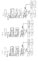
- Fig. 4 is a flowchart to diagnose the electric motor.
- Step S10 finds the total harmonic distortion (THD) of the harmonics contained in the current of the output power 2' shown in Fig. 1.
- the detection of the current harmonics can be done by using a well-known device such as a clamping measure or a non-contact electromagnetic field measure with a search coil.
- the harmonic orders from which to find the total harmonic distortion can be, for example, the 2nd to 40th orders.
- Step S11 performs index calculation to find an index value (TH k ) obtained by dividing the relative harmonic content of each order by the total harmonic distortion found at Step S10.
- step S12 determine deterioration.
- CH k is a criteria value of the Kth-order harmonics which will be described later, and is compared with TH k found at Step S11.
- Step S13 when the electric motor is in the normal condition, and to step S14 when it is deteriorated.
- the flowchart to diagnose the inverter is shown in Figs. 5A to 5C.
- Fig. 5A is a flowchart to diagnose the smoothing capacitor 5 shown in Fig. 1, and determines deterioration by measuring the current harmonics of the input power 1' shown in Fig. 1.
- Steps P100, P111 and P112 have the same calculation contents as in the Steps S10, S11, and S12 shown in Fig. 4.
- Fig. 5B is a flowchart to diagnose the converter part 4, the inverter part 6 and the control part 7 shown in Fig. 1, and determines deterioration by measuring the current harmonics of the output power 2' shown in Fig. 1.
- Steps P200, P211 and P212 have the same calculation contents as in the Steps P100, P111, and P112 shown in Fig. 5A.
- Fig. 5C is a flowchart to diagnose the drive part 8 shown in Fig. 1, and determines deterioration by measuring the current harmonics of the output power 2' shown in Fig. 1.
- Step P200' the 38th-order harmonic content is found, and the drive board is diagnosed (Step P201').
- Step P203' CH k is compared with the 38th-order harmonic content (H 38 ) to determine the good or bad of the drive board.
- CH k C k ⁇ f (M k ) where f (M k ) is the Kth-order harmonic function.
- the degrees of deterioration of the electric motor and inverter are discriminated into: “normal”; “caution needed”; and “defective” in order to show the quality. These "normal”, “ caution needed”, and “defective” are referred to as A, B and C, respectively for convenience.
- the level B "caution needed” is further discriminated into: light deterioration B1 (deterioration which will cause no problem in the operation for about a half year) ; intermediate deterioration B2 (deterioration which will allow about three month operation, but requires tendency control); and heavy deterioration B3 (deterioration which requires preparation for replacement or repair because of the high probability of defects in the devices) depending on the degree of deterioration of the devices.
- the aforementioned inspection period can be considered just as a guideline.
- a multivariate analysis technique is effective to perform an analysis by focusing on the relation between the current harmonics and the deteriorated part of the devices, so this technique will be described as follows.
- the basis analytical method which is one of the multivariate analyses is the most suitable.
- H k is the Kth-order harmonic content.
- f(N s ) can be the following values.
- I k represents the index value of the kth-order harmonics.
- f(N s ) ⁇ I k
- f(N c ) can be the following values.
- I k represents the index value of the kth-order harmonics.
- f(N c ) ⁇ I k -I 2 k : six function values of f(N c ) 11 , f(N c ) 13 , f(N c ) 17 , f(N c ) 19 , f(N c ) 23 , and f(N c ) 25 .
- f(Np) can be the following values.
- I k represents the index value of the kth-order harmonics.
- f (N p ) ⁇ I k -I 2 k : sixteen function values of f(N p ) 2 , f(N p ) 3 , f(N p ) 4 , f(N p ) 5 , f(N p ) 6 , f(N p ) 7 , f(N p ) 8 , f(N p ) 9 , f(N p ) 10 , f(N p ) 11 , f(N p ) 13 , f(N p ) 17 , f(N p ) 19 , f(N p ) 23 , f(N p ) 25 , and f(N p ) 38 .
- Examples of the electric equipment's deteriorated part and the distinction between the degrees of deterioration (A, B1, B2, B3 and C) described in the embodiment of the present invention are shown in Tables 3 and 4 below.
- the electric motor's deteriorated part and the distinction between the degrees of deterioration Electric Motor equipment Electric motor Equipment's deteriorated part Normal Caution needed (B) Defective (A) (B) (B2) (B3) (C) Electric motor's main body Rotary shaft and bearing, installment C 2 ⁇ f(M 2 ) (A) ⁇ 1.3 (B1) ⁇ 1.3 (B2) ⁇ 1.2 (B3) or more Insulation of stator winding (between phases or to the ground) C 3 ⁇ f(M 3 ) (A) ⁇ 1.3 (B1) ⁇ 1.3 (B2) ⁇ 1.2 (B3) or more Damage of bearing and housing C 4 ⁇ f(M 4 ) (A) ⁇ 1.3 (B1) ⁇ 1.3 (B2) ⁇ 1.2 (B3) or more Uneven air gaps (dirt adhe
- measuring current harmonics can determine the deteriorated part of an electric motor or inverter of electric equipment, and also can distinguish between the degrees of deterioration.
Landscapes
- Engineering & Computer Science (AREA)
- Power Engineering (AREA)
- Physics & Mathematics (AREA)
- General Physics & Mathematics (AREA)
- Tests Of Circuit Breakers, Generators, And Electric Motors (AREA)
- Inverter Devices (AREA)
- Testing Electric Properties And Detecting Electric Faults (AREA)
- Control Of Electric Motors In General (AREA)
- Control Of Ac Motors In General (AREA)
Applications Claiming Priority (5)
| Application Number | Priority Date | Filing Date | Title |
|---|---|---|---|
| JP2003030807 | 2003-02-07 | ||
| JP2003030807 | 2003-02-07 | ||
| JP2003036362 | 2003-02-14 | ||
| JP2003036362 | 2003-02-14 | ||
| PCT/JP2004/001154 WO2004070402A1 (ja) | 2003-02-07 | 2004-02-04 | 電気設備の高調波診断方法 |
Publications (2)
| Publication Number | Publication Date |
|---|---|
| EP1591795A1 true EP1591795A1 (de) | 2005-11-02 |
| EP1591795A4 EP1591795A4 (de) | 2011-07-06 |
Family
ID=32852687
Family Applications (1)
| Application Number | Title | Priority Date | Filing Date |
|---|---|---|---|
| EP04708066A Withdrawn EP1591795A4 (de) | 2003-02-07 | 2004-02-04 | Harmonisches diagnoseverfahren für eine elektrische anlage |
Country Status (5)
| Country | Link |
|---|---|
| US (1) | US7275003B2 (de) |
| EP (1) | EP1591795A4 (de) |
| JP (1) | JP3661155B2 (de) |
| KR (1) | KR100616272B1 (de) |
| WO (1) | WO2004070402A1 (de) |
Cited By (1)
| Publication number | Priority date | Publication date | Assignee | Title |
|---|---|---|---|---|
| EP3054307A1 (de) * | 2015-01-23 | 2016-08-10 | Rolls-Royce plc | Statorfehlererkennung und -diagnose |
Families Citing this family (20)
| Publication number | Priority date | Publication date | Assignee | Title |
|---|---|---|---|---|
| JP4802129B2 (ja) * | 2007-03-19 | 2011-10-26 | 株式会社東芝 | 電力品質評価システム |
| US7847579B2 (en) * | 2007-06-28 | 2010-12-07 | Gm Global Technology Operations, Inc. | Systems and methods to evaluate permanent magnet motors |
| JP4877397B2 (ja) * | 2010-01-22 | 2012-02-15 | 株式会社デンソー | 電流センサの異常診断装置、およびセンサの異常診断装置 |
| KR101140613B1 (ko) * | 2010-04-05 | 2012-05-02 | 한국전기연구원 | 전동기의 온-사이트 결함 진단 방법 |
| CN102928709B (zh) * | 2012-10-31 | 2015-08-12 | 广东电网公司东莞供电局 | 基于三相谐波的电容器组故障检测方法及系统 |
| JP6100188B2 (ja) * | 2014-03-11 | 2017-03-22 | 株式会社東芝 | 電力負荷推定装置、電力負荷推定システム、電力負荷推定方法及び電力負荷推定プログラム |
| JP6353694B2 (ja) * | 2014-05-13 | 2018-07-04 | 株式会社日立製作所 | 劣化診断システム |
| US9791343B2 (en) * | 2015-02-12 | 2017-10-17 | General Electric Company | Methods and systems to derive engine component health using total harmonic distortion in a knock sensor signal |
| CN110088589B (zh) | 2016-12-15 | 2020-12-11 | 三菱电机株式会社 | 动力传递机构的异常诊断装置以及动力传递机构的异常诊断方法 |
| CN107845999A (zh) * | 2017-11-30 | 2018-03-27 | 中电科芜湖钻石飞机制造有限公司 | 一种基于电流总谐波系数的电机故障检测系统及方法 |
| CN111448752B (zh) * | 2017-12-13 | 2023-07-14 | 三菱电机株式会社 | 电力转换装置及空气调节机 |
| JP2020153743A (ja) * | 2019-03-19 | 2020-09-24 | 株式会社戸上電機製作所 | 地絡要因推定装置、データ生成装置、地絡要因推定方法、データ生成方法及び地絡継電器 |
| CN111856171A (zh) * | 2019-04-24 | 2020-10-30 | 中矿龙科能源科技(北京)股份有限公司 | 基于谐波法的变频器和电力电容器故障诊断系统 |
| WO2021005662A1 (ja) * | 2019-07-05 | 2021-01-14 | 三菱電機株式会社 | 異常診断システムおよび異常診断方法 |
| JP6800352B1 (ja) * | 2019-07-24 | 2020-12-16 | 東芝三菱電機産業システム株式会社 | キャパシタ診断装置及びキャパシタ診断方法 |
| JP7363567B2 (ja) * | 2019-09-20 | 2023-10-18 | 富士電機株式会社 | モデル生成装置、電力変換装置及び電力制御システム |
| WO2022137291A1 (ja) * | 2020-12-21 | 2022-06-30 | 東芝三菱電機産業システム株式会社 | 寿命判定装置およびそれを備えた電源装置 |
| JPWO2023073870A1 (de) * | 2021-10-28 | 2023-05-04 | ||
| JPWO2023084600A1 (de) * | 2021-11-09 | 2023-05-19 | ||
| WO2023095256A1 (ja) * | 2021-11-25 | 2023-06-01 | 東芝三菱電機産業システム株式会社 | 無停電電源装置 |
Family Cites Families (5)
| Publication number | Priority date | Publication date | Assignee | Title |
|---|---|---|---|---|
| US4761703A (en) * | 1987-08-31 | 1988-08-02 | Electric Power Research Institute, Inc. | Rotor fault detector for induction motors |
| US5739698A (en) * | 1996-06-20 | 1998-04-14 | Csi Technology, Inc. | Machine fault detection using slot pass frequency flux measurements |
| JPH1183686A (ja) * | 1997-09-01 | 1999-03-26 | Nippon Steel Corp | 機械設備の異常診断方法およびその装置 |
| JP3671367B2 (ja) * | 2000-12-20 | 2005-07-13 | エイテック株式会社 | 電気機器設備の異常診断方法 |
| JP3561882B2 (ja) | 2001-09-03 | 2004-09-02 | エイテック株式会社 | 電気機器の劣化診断法 |
-
2004
- 2004-02-04 EP EP04708066A patent/EP1591795A4/de not_active Withdrawn
- 2004-02-04 WO PCT/JP2004/001154 patent/WO2004070402A1/ja not_active Ceased
- 2004-02-04 KR KR1020047005096A patent/KR100616272B1/ko not_active Expired - Lifetime
- 2004-02-04 US US10/525,227 patent/US7275003B2/en not_active Expired - Lifetime
- 2004-02-04 JP JP2004570946A patent/JP3661155B2/ja not_active Expired - Lifetime
Cited By (1)
| Publication number | Priority date | Publication date | Assignee | Title |
|---|---|---|---|---|
| EP3054307A1 (de) * | 2015-01-23 | 2016-08-10 | Rolls-Royce plc | Statorfehlererkennung und -diagnose |
Also Published As
| Publication number | Publication date |
|---|---|
| EP1591795A4 (de) | 2011-07-06 |
| KR20050044320A (ko) | 2005-05-12 |
| JP3661155B2 (ja) | 2005-06-15 |
| HK1087778A1 (zh) | 2006-10-20 |
| KR100616272B1 (ko) | 2006-08-28 |
| WO2004070402A1 (ja) | 2004-08-19 |
| US20060009932A1 (en) | 2006-01-12 |
| JPWO2004070402A1 (ja) | 2006-05-25 |
| US7275003B2 (en) | 2007-09-25 |
Similar Documents
| Publication | Publication Date | Title |
|---|---|---|
| EP1591795A1 (de) | Harmonisches diagnoseverfahren für eine elektrische anlage | |
| JP3671367B2 (ja) | 電気機器設備の異常診断方法 | |
| JP3561882B2 (ja) | 電気機器の劣化診断法 | |
| US6498992B1 (en) | Defect diagnosis method and defect diagnosis apparatus | |
| Trzynadlowski et al. | Diagnostics of mechanical abnormalities in induction motors using instantaneous electric power | |
| US20100169030A1 (en) | Machine condition assessment through power distribution networks | |
| Laadjal et al. | A novel indicator-based online diagnostics technique of interturn short-circuit faults in synchronous reluctance machines | |
| Radionov et al. | Information and measurement system for control of technical state of asynchronous electric motors with group supply from frequency converter | |
| CN100443907C (zh) | 用于电气设备的谐波诊断方法 | |
| JP3671369B2 (ja) | 電気機器の異常及び劣化診断装置 | |
| Barnish et al. | Motor maintenance: A survey of techniques and results | |
| Yelpale et al. | Fuzzy-based induction motor fault diagnosis decision-making system for motor current signature analysis | |
| KR100810979B1 (ko) | 유도전동기의 결함 검출 방법 | |
| Saad | The Utilisation of Information Available in a Sensorless Control System of an AC Induction Motor for Condition Monitoring | |
| Nejadpak et al. | A vibration-based diagnostic tool for analysis of superimposed failures in electric machines | |
| HK1087778B (en) | Method of harmonic diagnosis for electric equipment | |
| Dymov et al. | Motor current signature analysis for identification induction motor defects | |
| Misra et al. | An experimental study of rotor fault detection using motor current signature analysis based on neural networks | |
| Abu Saad | The Untilisation of Information Available in a Sensorless Control System of an AC Induction Motor for Condition Monitoring | |
| Strankowski et al. | Faults and fault detection methods in electric drives | |
| Penrose et al. | A multi-technology approach to motor diagnostics | |
| Troyer | Optimum Reference States for Precision Maintenance | |
| Suter | An Approach To Condition Monitoring And Fault Diagnosis Of Induction Machines Using Key Performance Indicators. | |
| Pivarčiová et al. | Development, research and design of a diagnostic system for measuring the course of temperatures, vibrations and noise | |
| Kral et al. | A stator and rotor fault detection technique for induction machines in traction applications for electric or hybrid electric vehicles |
Legal Events
| Date | Code | Title | Description |
|---|---|---|---|
| PUAI | Public reference made under article 153(3) epc to a published international application that has entered the european phase |
Free format text: ORIGINAL CODE: 0009012 |
|
| 17P | Request for examination filed |
Effective date: 20050718 |
|
| AK | Designated contracting states |
Kind code of ref document: A1 Designated state(s): AT BE BG CH CY CZ DE DK EE ES FI FR GB GR HU IE IT LI LU MC NL PT RO SE SI SK TR |
|
| AX | Request for extension of the european patent |
Extension state: AL LT LV MK |
|
| DAX | Request for extension of the european patent (deleted) | ||
| A4 | Supplementary search report drawn up and despatched |
Effective date: 20110608 |
|
| 17Q | First examination report despatched |
Effective date: 20120327 |
|
| STAA | Information on the status of an ep patent application or granted ep patent |
Free format text: STATUS: THE APPLICATION IS DEEMED TO BE WITHDRAWN |
|
| 18D | Application deemed to be withdrawn |
Effective date: 20120807 |