EP1591413A1 - Drop tube insert and apparatus adapted for use with a riser pipe - Google Patents
Drop tube insert and apparatus adapted for use with a riser pipe Download PDFInfo
- Publication number
- EP1591413A1 EP1591413A1 EP05009175A EP05009175A EP1591413A1 EP 1591413 A1 EP1591413 A1 EP 1591413A1 EP 05009175 A EP05009175 A EP 05009175A EP 05009175 A EP05009175 A EP 05009175A EP 1591413 A1 EP1591413 A1 EP 1591413A1
- Authority
- EP
- European Patent Office
- Prior art keywords
- drop tube
- tube insert
- wall
- insert
- end portion
- Prior art date
- Legal status (The legal status is an assumption and is not a legal conclusion. Google has not performed a legal analysis and makes no representation as to the accuracy of the status listed.)
- Granted
Links
- 239000007788 liquid Substances 0.000 claims abstract description 54
- 238000007789 sealing Methods 0.000 claims description 58
- 238000004891 communication Methods 0.000 claims description 21
- 239000012530 fluid Substances 0.000 claims description 10
- 239000000463 material Substances 0.000 description 14
- 239000000446 fuel Substances 0.000 description 6
- 238000002788 crimping Methods 0.000 description 5
- 230000007704 transition Effects 0.000 description 5
- 230000015572 biosynthetic process Effects 0.000 description 4
- 238000000034 method Methods 0.000 description 4
- 229910052782 aluminium Inorganic materials 0.000 description 3
- XAGFODPZIPBFFR-UHFFFAOYSA-N aluminium Chemical compound [Al] XAGFODPZIPBFFR-UHFFFAOYSA-N 0.000 description 3
- 238000003780 insertion Methods 0.000 description 3
- 230000037431 insertion Effects 0.000 description 3
- 239000004033 plastic Substances 0.000 description 3
- 229920003023 plastic Polymers 0.000 description 3
- 239000004215 Carbon black (E152) Substances 0.000 description 2
- LFQSCWFLJHTTHZ-UHFFFAOYSA-N Ethanol Chemical compound CCO LFQSCWFLJHTTHZ-UHFFFAOYSA-N 0.000 description 2
- 238000005429 filling process Methods 0.000 description 2
- 229930195733 hydrocarbon Natural products 0.000 description 2
- 150000002430 hydrocarbons Chemical class 0.000 description 2
- 238000004519 manufacturing process Methods 0.000 description 2
- 229910052751 metal Inorganic materials 0.000 description 2
- 239000002184 metal Substances 0.000 description 2
- 238000012986 modification Methods 0.000 description 2
- 230000004048 modification Effects 0.000 description 2
- 230000008569 process Effects 0.000 description 2
- 239000002002 slurry Substances 0.000 description 2
- 238000003860 storage Methods 0.000 description 2
- 239000004593 Epoxy Substances 0.000 description 1
- 229910000760 Hardened steel Inorganic materials 0.000 description 1
- 238000013459 approach Methods 0.000 description 1
- 230000009286 beneficial effect Effects 0.000 description 1
- 238000005520 cutting process Methods 0.000 description 1
- 239000002283 diesel fuel Substances 0.000 description 1
- 230000000694 effects Effects 0.000 description 1
- 230000007613 environmental effect Effects 0.000 description 1
- 239000003502 gasoline Substances 0.000 description 1
- 230000002401 inhibitory effect Effects 0.000 description 1
- 238000003754 machining Methods 0.000 description 1
- 238000000465 moulding Methods 0.000 description 1
- 150000002825 nitriles Chemical class 0.000 description 1
- 229920001296 polysiloxane Polymers 0.000 description 1
- 230000008439 repair process Effects 0.000 description 1
- 238000005096 rolling process Methods 0.000 description 1
- 239000000565 sealant Substances 0.000 description 1
- 239000007779 soft material Substances 0.000 description 1
Images


Classifications
-
- F—MECHANICAL ENGINEERING; LIGHTING; HEATING; WEAPONS; BLASTING
- F16—ENGINEERING ELEMENTS AND UNITS; GENERAL MEASURES FOR PRODUCING AND MAINTAINING EFFECTIVE FUNCTIONING OF MACHINES OR INSTALLATIONS; THERMAL INSULATION IN GENERAL
- F16L—PIPES; JOINTS OR FITTINGS FOR PIPES; SUPPORTS FOR PIPES, CABLES OR PROTECTIVE TUBING; MEANS FOR THERMAL INSULATION IN GENERAL
- F16L25/00—Construction or details of pipe joints not provided for in, or of interest apart from, groups F16L13/00 - F16L23/00
- F16L25/06—Construction or details of pipe joints not provided for in, or of interest apart from, groups F16L13/00 - F16L23/00 comprising radial locking means
- F16L25/08—Construction or details of pipe joints not provided for in, or of interest apart from, groups F16L13/00 - F16L23/00 comprising radial locking means in the form of screws, nails or the like
-
- B—PERFORMING OPERATIONS; TRANSPORTING
- B65—CONVEYING; PACKING; STORING; HANDLING THIN OR FILAMENTARY MATERIAL
- B65D—CONTAINERS FOR STORAGE OR TRANSPORT OF ARTICLES OR MATERIALS, e.g. BAGS, BARRELS, BOTTLES, BOXES, CANS, CARTONS, CRATES, DRUMS, JARS, TANKS, HOPPERS, FORWARDING CONTAINERS; ACCESSORIES, CLOSURES, OR FITTINGS THEREFOR; PACKAGING ELEMENTS; PACKAGES
- B65D90/00—Component parts, details or accessories for large containers
- B65D90/22—Safety features
- B65D90/26—Overfill prevention
-
- B—PERFORMING OPERATIONS; TRANSPORTING
- B65—CONVEYING; PACKING; STORING; HANDLING THIN OR FILAMENTARY MATERIAL
- B65D—CONTAINERS FOR STORAGE OR TRANSPORT OF ARTICLES OR MATERIALS, e.g. BAGS, BARRELS, BOTTLES, BOXES, CANS, CARTONS, CRATES, DRUMS, JARS, TANKS, HOPPERS, FORWARDING CONTAINERS; ACCESSORIES, CLOSURES, OR FITTINGS THEREFOR; PACKAGING ELEMENTS; PACKAGES
- B65D90/00—Component parts, details or accessories for large containers
-
- B—PERFORMING OPERATIONS; TRANSPORTING
- B65—CONVEYING; PACKING; STORING; HANDLING THIN OR FILAMENTARY MATERIAL
- B65D—CONTAINERS FOR STORAGE OR TRANSPORT OF ARTICLES OR MATERIALS, e.g. BAGS, BARRELS, BOTTLES, BOXES, CANS, CARTONS, CRATES, DRUMS, JARS, TANKS, HOPPERS, FORWARDING CONTAINERS; ACCESSORIES, CLOSURES, OR FITTINGS THEREFOR; PACKAGING ELEMENTS; PACKAGES
- B65D90/00—Component parts, details or accessories for large containers
- B65D90/22—Safety features
- B65D90/28—Means for preventing or minimising the escape of vapours
-
- B—PERFORMING OPERATIONS; TRANSPORTING
- B67—OPENING, CLOSING OR CLEANING BOTTLES, JARS OR SIMILAR CONTAINERS; LIQUID HANDLING
- B67D—DISPENSING, DELIVERING OR TRANSFERRING LIQUIDS, NOT OTHERWISE PROVIDED FOR
- B67D7/00—Apparatus or devices for transferring liquids from bulk storage containers or reservoirs into vehicles or into portable containers, e.g. for retail sale purposes
- B67D7/06—Details or accessories
- B67D7/32—Arrangements of safety or warning devices; Means for preventing unauthorised delivery of liquid
- B67D7/3209—Arrangements of safety or warning devices; Means for preventing unauthorised delivery of liquid relating to spillage or leakage, e.g. spill containments, leak detection
-
- B—PERFORMING OPERATIONS; TRANSPORTING
- B67—OPENING, CLOSING OR CLEANING BOTTLES, JARS OR SIMILAR CONTAINERS; LIQUID HANDLING
- B67D—DISPENSING, DELIVERING OR TRANSFERRING LIQUIDS, NOT OTHERWISE PROVIDED FOR
- B67D7/00—Apparatus or devices for transferring liquids from bulk storage containers or reservoirs into vehicles or into portable containers, e.g. for retail sale purposes
- B67D7/06—Details or accessories
- B67D7/78—Arrangements of storage tanks, reservoirs or pipe-lines
Definitions
- the present invention relates generally drop tube inserts and apparatus, and more specifically to drop tube inserts and apparatus adapted for use with a riser pipe of a liquid reservoir.
- Liquid fuels are generally stored in liquid reservoirs such as underground storage tanks, above ground tanks, or any of a variety of different containers.
- liquid fuel reservoirs have inlets and outlets through which fuel can be added to and/or removed from the reservoir.
- These inlets and outlets may typically consist of a riser pipe extending from the reservoir.
- a riser pipe Internal to the riser pipe is a drop tube and the space between the riser pipe and the drop tube is frequently referred to as the interstitial space between the riser pipe and the drop tube.
- the riser pipe is typically threaded to an adapter collar to which a fuel line can be coupled.
- a spill container surrounds the fill adapter collar and acts as a secondary containment system for any overflow or spillage that may occur during the filling process.
- the interstitial space between the riser pipe and the drop tube can allow an excessive amount of vapor to be introduced into the atmosphere, especially during the filling process.
- the interstitial space can act as a chimney for vapor to be released from the ullage of the tank.
- the interstitial space area is relatively small, because of this chimney effect, the vapor from the entire ullage area of the reservoir can be released through the interstitial space and may therefore create an environmental concern.
- U.S. Patent No. 6,523,581 there is a continuing desire to provide apparatus and methods for minimizing, such as preventing, release of vapors from an ullage area of the reservoir.
- an apparatus adapted for use with a riser pipe of a liquid reservoir includes a drop tube adapted for at least partial disposition in a riser pipe of a liquid reservoir.
- the drop tube includes a wall with inner and outer surfaces.
- the apparatus further includes a drop tube insert at least partially disposed within an end portion of the drop tube.
- the drop tube insert includes a wall with inner and outer surfaces wherein at least portions of the inner surfaces of the drop tube and drop tube insert cooperate to define a liquid flow path.
- the wall of the drop tube insert is devoid of any opening extending between its inner and outer surfaces.
- the apparatus further includes an interstitial space interposed between at least portions of the outer surface of the drop tube insert and the inner surface of the drop tube and a fastener extending through the wall of the drop tube and the interstitial space to engage the drop tube insert and to secure the drop tube insert relative to the drop tube.
- the apparatus also includes a first sealing member positioned between the outer surface of the drop tube insert and the inner surface of the drop tube. The first sealing member is operative to inhibit fluid communication between the interstitial space and the liquid flow path.
- a drop tube insert is provided that is adapted to be at least partially inserted into an interior area of a drop tube.
- the drop tube insert includes a wall with an inner surface, an outer surface, a first end portion, and a second end portion.
- the first end portion comprises a flared portion including a circumferential sealing surface for a sealing member.
- the outer surface includes at least one cavity that is adapted to receive a fastener.
- the wall of the drop tube insert is devoid of any openings extending between its inner and outer surfaces.
- a liquid communication assembly is provided that is adapted for use with a liquid reservoir.
- the assembly includes a spill restrictor, a riser pipe including a restrictor end and an inwardly facing surface.
- the riser pipe is attached to the spill restrictor at the restrictor end.
- the assembly further includes a drop tube at least partially disposed in the riser pipe, wherein the drop tube includes a wall with an inner surface and an outer surface.
- the assembly includes a drop tube insert at least partially disposed within an end portion of the drop tube.
- the drop tube insert includes a wall with inner and outer surfaces. At least portions of the inner surfaces of the drop tube and drop tube insert cooperate to define a liquid flow path.
- the wall of the drop tube insert is devoid of any opening extending between its inner and outer surfaces.
- the assembly also includes an interstitial space interposed between at least portions of the outer surface of the drop tube insert and the inner surface of the drop tube and a fastener that extends through the wall of the drop tube and the interstitial space to engage the drop tube insert and to secure the drop tube insert relative to the drop tube.
- the assembly still further includes a first sealing member positioned between the outer surface of the drop tube insert and the inner surface of the drop tube. The first sealing member is operative to inhibit fluid communication between the interstitial space and the liquid flow path.
- the assembly also includes a second sealing member engaging the restrictor end of the riser pipe and a portion of the drop tube insert.
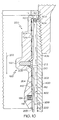
- FIG. 1 depicts an exemplary apparatus 250 for use with a riser pipe of a liquid reservoir, such as a liquid storage tank.
- the apparatus 250 includes a drop tube 200 adapted for at least partial disposition in a riser pipe 400 (see FIG. 9) of a liquid reservoir.
- the drop tube 200 includes a wall 202 with an inner surface 204 and an outer surface 206.
- the wall 202 can take many shapes in accordance with the concepts of the present invention.
- the wall 202 can include circular and/or noncircular cross sectional shapes.
- the wall may comprise a cylinder with a cylindrical wall wherein the inner surface 204 comprises an inner cylindrical surface and the outer surface 206 comprises an outer cylindrical surface.
- the drop tube 200 can be formed from a wide range of materials and can include materials that will not degrade when exposed to liquid being contained in an associated liquid reservoir.
- the drop tube 200 may be formed from materials that will not degrade when exposed to hydrocarbon liquids, slurries, or the like.
- Exemplary materials may include plastic, metal (e.g., aluminum), or the like.
- the apparatus 250 further includes a drop tube insert 100 at least partially disposed within an end portion of the drop tube 200.
- a drop tube insert 100 is shown as inserted partially within an end portion of the drop tube 200, in alternative embodiments the drop tube insert 100 may be inserted entirely into an interior area of the drop tube 200.
- the drop tube insert 100 includes a wall 102 with an inner surface 104 and an outer surface 106. At least portions of the inner surfaces 104, 204 of the drop tube insert 100 and drop tube 200 cooperate to define a liquid flow path 252.
- the wall 102 of the drop tube insert 100 can take a variety of shapes that may correspond to a shape of an interior portion of the drop tube 200.
- the wall 102 can include circular and/or noncircular cross sectional shapes.
- the wall 102 may comprise a cylinder wherein the wall 102 comprises a cylindrical wall, the inner surface 104 comprises an inner cylindrical surface and the outer surface 106 comprises an outer cylindrical surface.
- the drop tube insert 100 can also be formed from a wide range of materials and can include materials that will not degrade when exposed to liquid being contained in an associated liquid reservoir.
- the drop tube insert 100 may be formed from materials that will not degrade when exposed to hydrocarbon liquids, slurries, or the like.
- Exemplary materials may include plastic, metal (e.g., aluminum), or the like.
- the wall 102 of the drop tube insert 100 is devoid of any opening extending between its inner and outer surfaces.
- the drop tube insert 100 might include at least one cavity 112 in the outer surface 106 of the drop tube insert 100.
- the at least one cavity 112, if provided, may be adapted to receive a fastener 212 and/or may be adapted to receive a crimped portion 210 of the drop tube 200 as shown in FIG. 1.
- the cavity 112, if provided, can optionally include a threaded portion 114 adapted to receive the threaded shank of a fastener 212 and a countersunk portion 116 adapted to receive the head of the fastener 212 and a crimped portion 210 of the drop tube 200.
- the fastener 212 engages both the cavity 112 and the crimped portion 210 to provide a particularly strong connection between the drop tube insert 100 and the drop tube 200.
- the apertures may be initially threaded to later receive the threaded portion of a threaded fastener.
- the apertures may be initially nonthreaded (e.g., as shown in FIG. 8) and threads may be later cut into the cavity wall by a threaded portion of a fastener as the fastener is tightened.
- Further exemplary cavities might not include a threaded portion.
- Fasteners in these applications might comprise a rivet or other fastener adapted to engage a nonthreaded cavity.
- exemplary embodiments of the drop tube insert 100 may be provided without any cavities in the outer surface 106 of the drop tube insert 100.
- Providing the drop tube insert 100 without cavities may simplify fabrication and/or reduce material costs by eliminating the necessity of providing an area of increased wall thickness 120 to accommodate the cavity, eliminate the necessity of forming the cavities 112, and simplify formation of corresponding apertures in the drop tube 200.
- fasteners may be provided that act as set screws and/or the drop tube 200 may be crimped in place with respect to the drop tube insert with or without accompanying fasteners.
- Providing cavities may be desirable in particular applications where a particularly strong connection is desirable and can be obtained by the fastener connection and/or crimping a portion of the drop tube 200 into a portion of the cavity 112.
- an interstitial space 254 is interposed between at least portions of the outer surface 106 of the drop tube insert 100 and the inner surface 204 of the drop tube 200.
- the interstitial space 254 may result from a clearance between inner dimensions of the drop tube 200 and outer dimensions of the drop tube insert 100.
- the interstitial space 254 may also result from surface imperfections in the inner surface 204 of the drop tube 200 and/or the outer surface 106 of the drop tube insert 100.
- the distance between the inner surface 204 of the drop tube 200 and the outer surface 106 of the drop tube insert 100 may differ throughout the interstitial space 254.
- a sealing member 124 may be positioned between the outer surface 106 of the drop tube insert 100 and the inner surface 204 of the drop tube 200.
- the drop tube insert 100 might include a circumferential groove 118 adapted to at least partially receive the sealing member 124.
- the sealing member 124 can be operative to inhibit, such as prevent, fluid communication between the interstitial space 254 and the liquid flow path 252.
- the sealing member 124 can inhibit fluid communication between the interstitial space 254 and the liquid flow path 252 that might otherwise occur through area 253. Therefore, a vapor path, indicated by arrows 410 in FIG. 10, may be interrupted by the sealing member 124 to inhibit, such as prevent, introduction of vapor from the interstitial space 254 into the liquid flow path 252.
- sealing members may be incorporated with the concepts of the present invention.
- the sealing member might comprise a PolyPak® sealing member available from Parker-Hannifin Corporation.
- the PolyPak® sealing member might be beneficial to provide an excellent sealing function with a wide range of clearance distances and differing clearance distances between the opposed walls of the drop tube and the drop tube insert.
- the PolyPak® sealing member can provide a sufficient sealing function without the use of epoxy sealant.
- FIG. 1 depicts an exemplary drop tube insert 100 being secured to an end portion of a drop tube 200
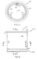
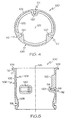
- FIGS. 2-5 illustrate particular features of the drop tube insert 100 in accordance with the illustrated exemplary embodiment.
- FIG. 2 is a top view while FIG. 3 is a front elevational view of the exemplary drop tube insert 100 from the apparatus of FIG. 1.
- FIG. 4 is a sectional view along line 4-4 of FIG. 3 and
- FIG. 5 is a sectional view along line 5-5 of FIG. 3.
- the outer surface 106 of the drop tube insert 100 can include at least one cavity 112.
- the at least one cavity may include a plurality of cavities that are radially disposed about a central axis 125 of the drop tube insert 100.
- the at least one cavity 112 comprises three cavities that are substantially equally radially disposed about the central axis 125 of the drop tube insert 100. Although three cavities are illustrated, it is understood that more or less than three cavities may be provided in accordance with the concepts of the present invention. Still further, the cavities may not be equally radially disposed about the central axis 125.
- providing three or more cavities 112 that are equally radially disposed may facilitate a substantially consistent interstitial space 254 between the outer and inner surfaces 106, 204 at the location of the sealing member 124.
- the fasteners 212 associated with the cavities 112 may provide forces that substantially counter one another. The countering forces may substantially center the drop tube insert 100 with respect to the drop tube 200 that may provide the interstitial space 254 with a desired and consistent distance between the outer and inner surfaces 106, 204 at the location of the sealing member 124.
- Providing a distance within a desired range and/or a substantially consistent distance within a desired range may enhance the effectiveness of the sealing member 124. Indeed, the effectiveness of sealing members are typically maximized when the distance between opposed walls to be sealed is maintained within a certain tolerance range that is acceptable for the particular sealing member in use.
- the wall 102 is devoid of any opening extending between its inner surface 104 and its outer surface 106.
- the cavity 112 is disposed in the wall 102 such that it does not extend between the inner surface 104 and outer surface 106 of the wall 102. Rather the blind end of the cavity 112 stops short of the inner surface 104, thereby avoiding fluid communication between the inner and outer surfaces 104, 106.
- avoiding fluid communication between the inner and outer surfaces 104, 106 assists in inhibiting, such as preventing, fluid communication between the interstitial space 254 and the liquid flow path 252.
- the wall may include areas of increased wall thickness 120 at locations adjacent each corresponding cavity 112.
- the areas of increased wall thickness 120 may be shaped as best shown in FIGS. 2 and 4 in order to facilitate formation of the drop tube insert 100 during a molding process.
- the exemplary drop tube insert 100 includes a first end portion 100a and a second end portion 100b.
- the first end portion 100a can include a circumferential sealing surface 110 for a sealing member (e.g., see 404 in FIG. 10) and the second end portion 100b may be provided with the circumferential groove 118 to at least partially receive the sealing member 124.
- the first end portion 100a may include a flared portion 108, such as a flange, that includes the circumferential sealing surface 110.
- the flared portion 108 may be formed by rolling, machining away portions of material, or by other fabrication processes.
- the circumferential sealing surface 110 may comprise a flat, rounded, and /or other surface configuration suitable for use with a corresponding sealing member.
- the circumferential sealing surface 110 may comprise a flat surface in combination with a rounded transition portion 111.
- the transition portion 111 may also act as an axial registration structure.
- the transition portion 111 comprises a concave rounded portion that eventually contacts the edge 201 of the end portion of the drop tube 200 to limit insertion of the drop tube insert 100 within the end portion of the drop tube 200.
- the wall 102 of the drop tube insert 100 may alternatively include a shoulder adapted to abut the edge 201 of the end portion of the tube 200 wherein the shoulder provides an axial registration structure.
- the wall 102 of the drop tube insert 100 may further include an area of increased thickness to accommodate the circumferential groove 118.
- Such area of increased thickness may include a streamlined ramp portion 105 designed to inhibit and/or prevent eddying and/or turbulence of liquid traveling through the liquid flow path 252.
- the drop tube insert 100 may include one or more registration structures that are designed to inhibit a relative movement between an alignment fixture 300 (See FIGS. 6-8) and the drop tube insert 100.
- the one or more registration structures of the drop tube insert 100 are designed to interact with the alignment fixture 300 in order to form one or more apertures 208 in the drop tube 200 at predetermined locations with respect to the drop tube insert 100.
- the registration structure of the drop tube insert 100 may comprise an axial registration structure and/or an angular registration structure.
- the drop tube insert 100 may be provided with an axial registration structure adapted to cooperate with an axial registration structure of the alignment fixture 300 to inhibit a relative axial movement between the drop tube insert 100 and the alignment fixture 300.
- the drop tube insert 100 includes an axial registration structure comprising an upper surface 109 of the flared portion 108 while the alignment fixture 300 includes an axial registration structure comprising an inner surface 307b of the alignment fixture 300.
- the upper surface 109 of the flared portion 108 is adapted to abut with the inner surface 307b of the alignment fixture 300 to inhibit a relative axial movement and thereby facilitate a relative axial position of the drop tube insert 100 and the alignment fixture 300 as shown in FIG. 8.
- the registration structure, if provided, of the drop tube insert 100 may also comprise an angular registration structure adapted to cooperate with an angular registration structure of the alignment fixture 300 to inhibit a relative angular movement between the alignment fixture 300 and the drop tube insert 100.
- the drop tube insert 100 includes an angular registration structure comprising a tongue 122 while the alignment fixture 300 includes an angular registration structure comprising a slot 306.
- the slot 306 of the alignment fixture 300 is adapted to receive the tongue 122 of the drop tube insert 100.
- the slot 306 may be inserted over the tongue to inhibit, such as prevent, a relative angular movement between the alignment fixture 300 and the drop tube insert 100 and thereby facilitate a relative angular position of the drop tube insert 100 and the alignment fixture 300 as shown in FIG. 8.
- the angular registration structure of the alignment fixture may alternatively comprise a recess, such as a groove, adapted to receive the tongue from the tube insert.
- the tube insert can alternatively include a slot or recess adapted to receive a tongue of the alignment fixture.
- the angular registration structures might comprise a pair of cooperating inclined shoulders wherein the shoulders are designed to approach one another as the alignment fixture is twisted relative to the drop tube insert until the shoulders abut one another at the desired relative angular position.
- the angular registration structure may also include a noncircular shape of the drop tube insert and/or the alignment fixture to facilitate the relative angular position.
- the registration structure of the drop tube insert 100 may comprise a single structure that provides both an axial and an angular registration function.
- a single tongue may function as an axial stop while also providing an angular registration function.
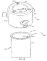
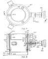
- FIG. 6 depicts an exemplary system 600 adapted to cooperate with a drill 350 (see FIGS. 7 and 8).
- the exemplary system 600 comprises the drop tube insert 100, the drop tube 200, and the alignment fixture 300.
- the drop tube insert 100 is at least partially disposed within an end portion of the drop tube 200.
- the drop tube insert 100 may slide downward with respect to the drop tube 200 until the transition portion 111, acting as an axial registration structure, abuts against the edge 201 of the end portion of the drop tube 200 (see FIG. 8).
- the at least one cavity 112 of the drop tube insert 100 is hidden behind the wall 202 of the drop tube 200 in instances where the drop tube wall 202 is opaque (see FIG. 6).
- the alignment fixture 300 may be provided to assist in forming apertures in the drop tube wall 202 that are each aligned with a corresponding one of the cavities 112 of the drop tube insert 100.
- the alignment fixture 300 may include one or more registration structures to inhibit a relative movement between the alignment fixture 300 and the drop tube insert 100.
- the alignment fixture 300 can include an angular registration structure comprising a slot 306 adapted to cooperate with an angular registration structure comprising a tongue 122 of the drop tube insert 100 to inhibit relative angular movement between the alignment fixture 300 and the drop tube insert 100.
- the angular registration structure of the alignment fixture 300 can take a variety of alternative forms to inhibit a relative angular movement between the alignment fixture 300 and the drop tube insert 100.
- the one or more registration structures of the alignment fixture 300 may comprise an axial registration structure to inhibit a relative axial movement between the alignment fixture 300 and the drop tube insert 100.
- the axial registration structure if provided, may comprise an inner surface 307b of a bridge flange 307.
- the inner surface 307b of the bridge flange 307 is adapted to abut the upper surface 109 of the flared portion 108 of the drop tube insert 100 to act as a stop and thereby inhibit a relative axial movement between the alignment fixture 300 and the drop tube insert 100.
- the bridge flange 307 also includes a plurality of view ports 307a, e.g., apertures, that permit observation of a relative axial orientation between the alignment fixture 300 and the drop tube insert 100.
- the alignment fixture 300 also includes a plurality of alignment devices 310 adapted to receive a drill bit 354 of a drill 350 for forming the one or more apertures 208 through the wall 202 of the drop tube 200.
- the alignment fixture 300 includes a body portion 301 wherein the alignment device 310 is adjustably mounted to the body portion 301. Indeed, as shown in the body portion 301 includes a mounting aperture 308 wherein at least a portion of the alignment device 310 is adapted to adjustably engage the mounting aperture 308. Providing adjustability between the alignment device 310 and the body portion 301 can introduce many advantages to the alignment fixture 300.
- the adjustability of the alignment device 310 with respect to the body portion 301 may provide an alignment device 310 that is adapted to clamp the alignment fixture 300 to the drop tube 200 to thereby inhibit relative axial and angular rotation between the alignment fixture 300 and the drop tube insert 200.
- providing three or more adjustable alignment devices 310 allows the alignment fixture 300 to be mounted such that it is appropriately centered with respect to the drop tube insert 100 and the drop tube 200.
- the alignment devices 310 may be removable from the corresponding mounting apertures 308. Removability of the alignment devices 310 from the mounting apertures 308 permits replacement or facilitates repair of worn alignment devices 310 without replacing the entire mounting fixture 300.
- Adjustability between the mounting device 310 and the body portion 301 is achieved by providing the alignment device 310 with a threaded shaft 314 adapted to adjustably engage a threaded mounting aperture 308 of the body portion 301.
- An exterior surface 316 of the alignment devices 310 may be knurled or otherwise provided with a gripping surface to facilitate tightening of the alignment devices 310 in use.
- each of the alignment devices 310 can be incrementally rotated to provide a centering function while sufficiently clamping the alignment fixture 300 relative to the drop tube 200 to substantially inhibit, such as prevent, relative axial and angular rotation therebetween.
- the alignment devices 310 further includes an elongated alignment aperture 313 adapted to align the drill bit 354 of the drill 350 with respect to a location on the drop tube 200 where the corresponding aperture 208 is to be formed.
- the alignment device 310 also includes a drill bit guard 312, such as a hardened steel bushing, adapted to facilitate an alignment function while protecting the remaining portions of the alignment device 310 from damage by the drill bit 354 of the drill 350.
- the drill bit guard 312 may be particularly useful in applications where the alignment device 310 is otherwise formed from a relatively soft material, such as aluminum, plastics or the like.
- the body portion 301 of the alignment fixture 300 includes an outer flange 302, an inner flange 304 spaced from the outer flange 302 and a bridge flange 307 attached between the outer flange 302 and the inner flange 304.
- the outer flange 302, inner flange 304 and bridge flange 307 comprise substantially continuous walls in order to provide a substantially rigid and durable structure capable of performing the alignment function.
- the alignment device 310 is mounted to the outer flange 302, the inner flange 304 comprises the previously-mentioned angular registration structure, e.g., the slot 306, while the bridge flange 307 provides the previously-mentioned view ports 307a, e.g., apertures, and axial registration structure, e.g., the inner surface 307b of the bridge flange 307.
- the outer flange 302 may also include an access window 305 to permit entry of a cutting tool and thereby facilitate formation of the slot 306 when fabricating the alignment fixture 300.
- An installer is first provided with a drop tube 200 including an end portion and a wall 202 with an inner surface 204 and an outer surface 206.
- the installer is further provided with a drop tube insert 100 including a registration structure and a wall 102 with an inner surface 104 and an outer surface 106.
- the wall 102 of the drop tube insert 100 is provided with at least one cavity 112 in the outer surface 106 of the drop tube insert 100.
- the wall 102 of the drop tube insert 100 is also devoid of any openings extending through its inner and outer surfaces.
- the installer is provided with an alignment fixture 300 adapted to cooperate with the registration structure of the tube insert 100 to inhibit a relative movement between the alignment fixture 300 and the tube insert 100.
- the alignment fixture 300 is provided with a plurality of alignment devices 310.
- the installer is provided with drill 350 for forming an aperture through the wall of the tube.
- the installer may first cut the drop tube 200 to the appropriate length depending on the particular application.
- the tube insert 100 and any associated seal 124 are then disposed at least partially within the end portion of the tube 200, e.g., see FIGS. 6 and 8.
- the second end portion 100b of the tube insert 100 is inserted into the end portion of the tube 200 and the tube insert 100 is then further inserted into an interior area of the tube 200 until the transition portion 111 or other portion of the flared portion 108 engages an edge 201 of the tube 200.
- the outer surface 106 of the drop tube insert 100 may be provided with a shoulder or other stop to provide a predetermined registration between the tube insert 100 and the tube 200. In still further embodiments, no stop is engaged wherein a flared portion 108 of the tube insert 100 is spaced from the edge 201 of the tube 200.
- the alignment fixture 300 is then positioned relative to the tube insert 100.
- the alignment fixture 300 is positioned relative to the tube insert 100 such that the alignment fixture 300 engages the registration structure of the tube insert 100 to inhibit a relative movement between the alignment fixture 300 and the tube insert 100 and to align the alignment device 310 with respect to the at least one cavity 112 in the wall 102 of the tube insert 100.
- the registration structure of the tube insert 100 includes an angular registration structure, wherein the alignment fixture 300 is positioned relative to the tube insert 100 such that the alignment fixture 300 engages the angular registration structure of the tube insert 100 to inhibit a relative angular movement between that alignment fixture 300 and the tube insert 100.
- the tube insert is provided with an angular registration structure comprising a tongue 122 and the alignment fixture is provided with an angular registration structure comprising a slot 306, wherein the alignment fixture 300 is positioned relative to the tube insert 100 by inserting the slot 306 over the tongue 122.
- the registration structure of the tube insert 100 includes an axial registration structure, wherein the alignment fixture 300 is positioned relative to the tube insert 100 such that the alignment fixture 300 engages the axial registration structure of the tube insert 100 to inhibit a relative axial movement between that alignment fixture 300 and the tube insert 100.
- the tube insert is provided with an axial registration structure comprising the upper surface 109 of the flared portion 108 and the alignment fixture is provided with an axial registration structure comprising an inner surface 307b of a bridge flange 307, wherein the alignment fixture 300 is positioned relative to the tube insert 100 moving the alignment fixture 300 relative to the tube insert 100 until the inner surface 307b of the bridge flange 307 abuts the upper surface 109 of the flared portion 108.
- the installer uses the view ports 307a, e.g., apertures, to view the relative position of the alignment fixture 300 relative to the tube insert 100.
- a plurality of view ports 307a are provided and the relative position of the alignment fixture 300 relative to the tube insert 100 is viewed at a plurality of locations, with the plurality of view ports 307a, to ensure a proper relative position between the alignment fixture 300 and the tube insert 100 about the periphery of the alignment fixture 300.
- the installer clamps the alignment fixture 300 relative to the tube 200 with the adjustable alignment devices 310 such that the alignment fixture 300 is clamped to the tube 200.
- Adjustment might involve incremental rotation of each alignment device 310 with respect to the body portion 301 until adequate clamping and centering of the tube 200 with respect to the alignment fixture 300 is achieved.
- the tube insert 100 may be axially and angularly registered with respect to the alignment fixture 300 as discussed above, the tube insert 100 may also be effectively coupled to the tube 200 by clamping the alignment fixture 300 to the tube 200.
- the installer may form the one or more apertures 208 in the wall 202 of the tube 200 with the drill bit 354 of the drill 350.
- the drill bit 354 is inserted within the elongated alignment aperture 313 of each alignment device 310 until the drill bit 354 forms the aperture 208 in the wall 202 of the tube 200.
- the end of a chuck 352 of the drill 350 may is designed to abut the end of the alignment device 310, as shown in FIGS. 7 and 8, to limit the insertion of the drill bit 354.
- the drill bit 354 is capable of following through formation of the aperture 208 by entering the cavity 112 but does not engage the wall 102 of the tube insert 100.
- a spacing collar may be provided adjacent the chuck to limit insertion of the drill bit.
- the installer may then remove the alignment fixture 300 and crimp a portion 210 of the tube 200 into the cavity 112 as shown in FIG. 1.
- Such crimping function may be performed with a crimping tool wherein a hammer, such as a mallet, may be used with the crimping tool to crimp portions 210 of the tube 200, adjacent the aperture 208, into the cavity 112.
- the cavity 112 of the tube insert 100 and the aperture 208 of the tube 200 may be used to secure the tube insert 100 to the tube 200 with a fastener 212.
- a fastener 212 e.g., screw, rivet or the like, may be inserted into the cavity 112 such that the fastener 212 engages the crimped portion 210 and the cavity 112. It is also contemplated that the fastener 212 may be attached without a crimped portion 210 or the crimped portion 210 may be formed when engaging the fastener 212 with the cavity.
- FIGS. 9 and 10 of the present invention depict a liquid communication assembly 500 that incorporates an exemplary apparatus 250 in accordance with the present invention.
- the liquid communication assembly 500 includes a spill restrictor 502 and a riser pipe 400 attached to the spill restrictor and having an inwardly facing surface 402.
- the drop tube 200 is at least partially disposed in the riser pipe 400. As best shown in FIG.
- an interstitial space 406 is defined between the outer surface 206 of the drop tube wall 202 and the inwardly facing surface 402 of the riser pipe 400.
- the sealing member 404 engages a restrictor end 408 of the riser pipe 400 and the circumferential sealing surface 110 of the drop tube insert 100. Accordingly, the sealing member 404 provides a sealing connection between the drop tube insert 100 and the riser pipe 400 to inhibit vapor leakage from the interstitial space 406 to the surrounding environment or into the liquid flow path 252.
- the sealing member 404 may take a variety of shapes to perform a sealing function. In one example, the sealing member comprises an O-ring with an initial circular cross section prior to being compressed. The sealing member 404 can also be preformed substantially to the shape shown in FIG. 10. Still further, the sealing member 404 might have other cross sectional shapes such as a triangular cross sectional shape or the like.
- the sealing member 124 is positioned between the outer surface 106 of the drop tube insert 100 and the inner surface 204 of the drop tube 200 is operative to inhibit fluid communication between the interstitial space 254 and the liquid flow path 254.
- cavities 112 may be provided in the outer surface 106 of the drop tube insert 100, the cavities 112 do not extend between the inner surface 104 and the outer surface 106 of the drop tube insert 100. Therefore, while cavities 112 may be provided to assist in fastening the drop tube insert 100 to the drop tube 200, the drop tube insert 100 is devoid of any opening extending between its inner and outer surfaces 104, 106 that might otherwise provide a vapor path from the interstitial space 406 to the liquid flow path 252.
- Sealing members in accordance with exemplary embodiments of the present invention may be made from, among other materials, rubber materials such as flourosilicone, flouroelastomer, nitrile or silicone, for example. Suitable materials might include those that exhibit good resistance to fuel attack while also maintaining good rebound characteristics for sealing. Other materials, as would be known to those skilled in the art, may be appropriate.
Landscapes
- Engineering & Computer Science (AREA)
- Mechanical Engineering (AREA)
- General Engineering & Computer Science (AREA)
- Gasket Seals (AREA)
- Branch Pipes, Bends, And The Like (AREA)
- Filling Or Discharging Of Gas Storage Vessels (AREA)
- Connection Of Plates (AREA)
- Loading And Unloading Of Fuel Tanks Or Ships (AREA)
- Quick-Acting Or Multi-Walled Pipe Joints (AREA)
- Joints With Sleeves (AREA)
- Filling Of Jars Or Cans And Processes For Cleaning And Sealing Jars (AREA)
Abstract
Description
Claims (21)
- An apparatus adapted for use with a riser pipe of a liquid reservoir, comprising:a) a drop tube adapted for at least partial disposition in a riser pipe of a liquid reservoir, the drop tube including a wall with inner and outer surfaces;b) a drop tube insert at least partially disposed within an end portion of the drop tube, the drop tube insert including a wall with inner and outer surfaces, at least portions of the inner surfaces of the drop tube and drop tube insert cooperating to define a liquid flow path, the wall of the drop tube insert being devoid of any opening extending between its inner and outer surfaces;c) an interstitial space interposed between at least portions of the outer surface of the drop tube insert and the inner surface of the drop tube;d) a fastener extending through the wall of the drop tube and the interstitial space to engage the drop tube insert and to secure the drop tube insert relative to the drop tube; ande) a first sealing member positioned between the outer surface of the drop tube insert and the inner surface of the drop tube, the first sealing member being operative to inhibit fluid communication between the interstitial space and the liquid flow path.
- The apparatus of claim 1, wherein the drop tube insert includes a first end portion and a second end portion, wherein the first end portion is provided with a circumferential sealing surface for a second sealing member and wherein the second end portion is provided with the first sealing member positioned between the outer surface of the second end portion and the inner surface of the drop tube.
- The apparatus of claim 2, wherein the first end portion comprises a flared portion including the circumferential sealing surface.
- The apparatus of claim 1, wherein the drop tube insert includes a cavity in the outer surface of the drop tube insert.
- The apparatus of claim 4, wherein the drop tube includes a crimped portion that extends into the cavity.
- The apparatus of claim 5, further including a fastener engaging the cavity and the crimped portion.
- The apparatus of claim 1, wherein the drop tube insert includes a registration structure.
- The apparatus of claim 7, wherein the registration structure comprises an angular registration structure.
- The apparatus of claim 7, wherein the registration structure comprises a tongue.
- The apparatus of claim 1, wherein the wall of the drop tube and the wall of the drop tube insert each comprise a cylindrical wall.
- A drop tube insert adapted to be at least partially inserted into an interior area of a drop tube, the drop tube insert comprising:a wall with an inner surface, an outer surface, a first end portion, and a second end portion, wherein the first end portion comprises a flared portion including a circumferential sealing surface for a sealing member, the outer surface includes at least one cavity that is adapted to receive a fastener, and the wall is devoid of any openings extending between its inner and outer surfaces.
- The drop tube insert of claim 11, further comprising a registration structure.
- The drop tube insert of claim 12, wherein the registration structure comprises an angular registration structure.
- The drop tube insert of claim 12, wherein the registration structure comprises a tongue.
- The drop tube insert of claim 11, wherein the wall comprises a cylindrical wall.
- The drop tube insert of claim 11, wherein the second end portion includes a circumferential groove adapted to receive another sealing member.
- A liquid communication assembly adapted for use with a liquid reservoir, the assembly comprising:a) a spill restrictor;b) a riser pipe including a restrictor end and an inwardly facing surface, wherein the riser pipe is attached to the spill restrictor at the restrictor end;c) a drop tube at least partially disposed in the riser pipe and including a wall with an inner surface and an outer surface;d) a drop tube insert at least partially disposed within an end portion of the drop tube, the drop tube insert including a wall with inner and outer surfaces, at least portions of the inner surfaces of the drop tube and drop tube insert cooperating to define a liquid flow path, the wall of the drop tube insert being devoid of any opening extending between its inner and outer surfaces;e) an interstitial space interposed between at least portions of the outer surface of the drop tube insert and the inner surface of the drop tube;f) a fastener extending through the wall of the drop tube and the interstitial space to engage the drop tube insert and to secure the drop tube insert relative to the drop tube;g) a first sealing member positioned between the outer surface of the drop tube insert and the inner surface of the drop tube, the first sealing member being operative to inhibit fluid communication between the interstitial space and the liquid flow path; andh) a second sealing member engaging the restrictor end of the riser pipe and a portion of the drop tube insert.
- The liquid communication assembly of claim 17, wherein the drop tube insert includes a first end portion comprising a flared portion including a circumferential sealing surface that engages the second sealing member.
- The liquid communication assembly of claim 17, wherein the drop tube insert includes a second end portion comprising a circumferential groove that receives at least a portion of the first sealing member.
- The liquid communication assembly of claim 17, wherein the wall of the drop tube and the wall of the drop tube insert each comprise a cylindrical wall.
- The liquid communication assembly of claim 17, wherein the drop tube insert comprises a registration structure.
Applications Claiming Priority (2)
| Application Number | Priority Date | Filing Date | Title |
|---|---|---|---|
| US836978 | 2004-04-30 | ||
| US10/836,978 US7069965B2 (en) | 2004-04-30 | 2004-04-30 | Drop tube inserts and apparatus adapted for use with a riser pipe |
Publications (2)
| Publication Number | Publication Date |
|---|---|
| EP1591413A1 true EP1591413A1 (en) | 2005-11-02 |
| EP1591413B1 EP1591413B1 (en) | 2009-02-11 |
Family
ID=34935791
Family Applications (1)
| Application Number | Title | Priority Date | Filing Date |
|---|---|---|---|
| EP05009175A Expired - Lifetime EP1591413B1 (en) | 2004-04-30 | 2005-04-27 | Drop tube insert and apparatus adapted for use with a riser pipe |
Country Status (11)
| Country | Link |
|---|---|
| US (1) | US7069965B2 (en) |
| EP (1) | EP1591413B1 (en) |
| JP (1) | JP2005320068A (en) |
| KR (1) | KR101050556B1 (en) |
| CN (1) | CN1693165B (en) |
| AT (1) | ATE422481T1 (en) |
| BR (1) | BRPI0503141A (en) |
| CA (1) | CA2503927C (en) |
| DE (1) | DE602005012646D1 (en) |
| ES (1) | ES2322273T3 (en) |
| TW (1) | TWI333920B (en) |
Families Citing this family (13)
| Publication number | Priority date | Publication date | Assignee | Title |
|---|---|---|---|---|
| US7128102B2 (en) | 2004-04-30 | 2006-10-31 | Delaware Capital Formation, Inc. | Drop tube segments adapted for use with a liquid reservoir |
| US7213610B2 (en) | 2004-04-30 | 2007-05-08 | Delaware Capital Formation, Inc. | Drop tube segments adapted for use with a liquid reservoir and methods |
| US7243675B2 (en) * | 2004-04-30 | 2007-07-17 | Delaware Capital Formation, Inc. | Drop tube segments adapted for use with a liquid reservoir |
| US7437815B2 (en) * | 2004-04-30 | 2008-10-21 | Delaware Capital Formation, Inc. | Systems adapted to cooperate with an aperture forming tool and methods |
| US9175796B2 (en) | 2008-02-22 | 2015-11-03 | Bulk Tank, Inc. | Hopper tee with comformable arcuate closure member |
| US8622097B2 (en) * | 2008-03-04 | 2014-01-07 | Delaware Capital Formation, Inc. | Spill containment apparatus for storage tanks |
| CA2716660C (en) | 2009-10-16 | 2018-02-20 | Franklin Fueling Systems, Inc. | Spill containment system |
| US20150001258A1 (en) * | 2012-02-24 | 2015-01-01 | Meadwestvaco Calmar, Inc. | Reusable aerosol actuator devices |
| BR112015005661B1 (en) | 2012-09-14 | 2021-03-16 | Franklin Fueling Systems, Inc | overflow prevention valves |
| CN104959574B (en) * | 2015-07-08 | 2017-03-01 | 中钢集团洛阳耐火材料研究院有限公司 | A kind of low pressure cast steel stalk and preparation method thereof |
| CN106628720B (en) * | 2015-11-02 | 2019-01-18 | 张国基 | Movable anti-overflow device |
| CN108996067A (en) * | 2018-09-27 | 2018-12-14 | 深圳全息安环科技有限公司 | Gas station's sample oil returns tank safety device |
| US11402034B2 (en) | 2019-09-19 | 2022-08-02 | Ron Ramies Automotive Inc. | Underground storage tank drop tube removal device and method of removing an underground storage tank drop tube |
Citations (4)
| Publication number | Priority date | Publication date | Assignee | Title |
|---|---|---|---|---|
| GB966842A (en) * | 1962-06-07 | 1964-08-19 | Shell Int Research | Pipe coupling |
| FR2194908A1 (en) * | 1972-07-31 | 1974-03-01 | Ciccolallo Gino | |
| US4479669A (en) * | 1982-04-01 | 1984-10-30 | Hydril Company | Pipe connector with threaded latch screws |
| US20020179178A1 (en) * | 2001-06-05 | 2002-12-05 | Pendleton David R. | Apparatus and method for minimizing vapor loss |
Family Cites Families (34)
| Publication number | Priority date | Publication date | Assignee | Title |
|---|---|---|---|---|
| US1313386A (en) | 1919-08-19 | Ftjitnel | ||
| US979819A (en) | 1910-03-31 | 1910-12-27 | Dover Stamping & Mfg Company | Funnel. |
| US1246033A (en) | 1916-03-17 | 1917-11-13 | Ernest A Adams | Funnel. |
| US1268947A (en) | 1916-05-11 | 1918-06-11 | Clarence T Fell | Funnel. |
| US1219222A (en) | 1916-05-13 | 1917-03-13 | Frederick C Baxter | Funnel. |
| US1289490A (en) | 1917-12-05 | 1918-12-31 | Elmer E Lundstrom | Funnel. |
| US1689066A (en) | 1926-06-11 | 1928-10-23 | Frederick C Baxter | Automatic shut-off device for liquid dispensers |
| US2340936A (en) | 1941-04-07 | 1944-02-08 | Phillips Petroleum Co | Filling device |
| US2499409A (en) | 1943-09-03 | 1950-03-07 | Bastian Blessing Co | Liquefied petroleum gas dispensing system |
| US2507545A (en) | 1948-04-22 | 1950-05-16 | Samiran David | Automatic shutoff valve for fuel nozzles |
| US2685891A (en) | 1948-06-07 | 1954-08-10 | August L Segelhorst | Automatic fluid control means |
| US2811179A (en) | 1954-05-07 | 1957-10-29 | Dolphice H Greenwood | Tank car loader |
| US2839082A (en) | 1956-03-09 | 1958-06-17 | Vapor Heating Corp | Train line end valve |
| US2918931A (en) | 1957-04-24 | 1959-12-29 | Penn Controls | Air charger for pressurized tanks |
| US2918932A (en) | 1957-05-01 | 1959-12-29 | Penn Controls | Float linkage for air charger |
| US3078867A (en) | 1961-06-21 | 1963-02-26 | John J Mcgillis | Liquid delivery control |
| US3610273A (en) | 1969-03-13 | 1971-10-05 | Peters & Russel Inc | Compressor or like intake valve |
| US3661175A (en) | 1970-05-25 | 1972-05-09 | Marotta Scientific Controls | Contamination resistant fluid flow fuse |
| GB1365306A (en) | 1970-09-08 | 1974-08-29 | Girling Ltd | Fluid flow control valves |
| FR2205166A5 (en) | 1972-10-26 | 1974-05-24 | Lafon Georges | |
| US3794077A (en) | 1972-12-15 | 1974-02-26 | C Fanshier | Excess flow check valve |
| FR2270198A1 (en) | 1974-02-18 | 1975-12-05 | Aster Boutillon Volucompteurs | Overflow prevention equipment for fuel tank - has automatic and manual stop valves in filling hose with pressure reducer |
| US3963041A (en) | 1974-02-27 | 1976-06-15 | Mcgillis Engineering, Inc. | Safety shutoff valve |
| FR2300951A1 (en) | 1975-02-13 | 1976-09-10 | Lafon Georges | CONTAINER VALVE CLOSING DEVICE |
| FR2331732A1 (en) | 1975-11-12 | 1977-06-10 | Lafon Georges | Automatic valve for filling tank - has float to operate valve element released by head contacting levers |
| FR2355736A1 (en) | 1976-06-22 | 1978-01-20 | Gallier Sa Andre | Self closing valve for submerged fuel tanks - has float controlled valve in fuel inlet and bleed for overspill |
| US4308894A (en) | 1980-01-15 | 1982-01-05 | Carpentier Urgel R | Dust trap and valve with auxiliary pressure equalizing valve |
| US4667711A (en) | 1984-05-10 | 1987-05-26 | Draft Roger A | Tank overfill valve |
| US4896705A (en) * | 1987-02-24 | 1990-01-30 | Emco Wheaton, Inc. | Containment manhole |
| US4793387A (en) | 1987-09-08 | 1988-12-27 | Enterprise Brass Works, Inc. | Overfill spillage protection device |
| US4986320A (en) | 1987-10-13 | 1991-01-22 | Kesterman James E | Drop tube having an overfill valve |
| US5117877A (en) | 1990-11-21 | 1992-06-02 | Sharp Bruce R | Overfill assembly made of polymeric material |
| US6267156B1 (en) | 2000-06-02 | 2001-07-31 | Toby Argandona | Filling station equipment for fumes emission prevention |
| US6655418B1 (en) * | 2000-10-27 | 2003-12-02 | Mcgill Milton Daniel | Drop tube seal for petroleum underground storage tanks |
-
2004
- 2004-04-30 US US10/836,978 patent/US7069965B2/en not_active Expired - Lifetime
-
2005
- 2005-04-07 CA CA2503927A patent/CA2503927C/en not_active Expired - Lifetime
- 2005-04-26 TW TW094113308A patent/TWI333920B/en not_active IP Right Cessation
- 2005-04-27 EP EP05009175A patent/EP1591413B1/en not_active Expired - Lifetime
- 2005-04-27 AT AT05009175T patent/ATE422481T1/en not_active IP Right Cessation
- 2005-04-27 DE DE602005012646T patent/DE602005012646D1/en not_active Expired - Lifetime
- 2005-04-27 ES ES05009175T patent/ES2322273T3/en not_active Expired - Lifetime
- 2005-04-29 CN CN2005100700230A patent/CN1693165B/en not_active Expired - Fee Related
- 2005-04-29 KR KR1020050036246A patent/KR101050556B1/en not_active Expired - Fee Related
- 2005-05-02 JP JP2005134464A patent/JP2005320068A/en not_active Withdrawn
- 2005-05-02 BR BR0503141-9A patent/BRPI0503141A/en not_active IP Right Cessation
Patent Citations (4)
| Publication number | Priority date | Publication date | Assignee | Title |
|---|---|---|---|---|
| GB966842A (en) * | 1962-06-07 | 1964-08-19 | Shell Int Research | Pipe coupling |
| FR2194908A1 (en) * | 1972-07-31 | 1974-03-01 | Ciccolallo Gino | |
| US4479669A (en) * | 1982-04-01 | 1984-10-30 | Hydril Company | Pipe connector with threaded latch screws |
| US20020179178A1 (en) * | 2001-06-05 | 2002-12-05 | Pendleton David R. | Apparatus and method for minimizing vapor loss |
Also Published As
| Publication number | Publication date |
|---|---|
| CN1693160A (en) | 2005-11-09 |
| CA2503927A1 (en) | 2005-10-30 |
| TW200535053A (en) | 2005-11-01 |
| BRPI0503141A (en) | 2006-01-10 |
| US20050241723A1 (en) | 2005-11-03 |
| CA2503927C (en) | 2012-06-12 |
| KR20060045870A (en) | 2006-05-17 |
| US7069965B2 (en) | 2006-07-04 |
| JP2005320068A (en) | 2005-11-17 |
| TWI333920B (en) | 2010-12-01 |
| EP1591413B1 (en) | 2009-02-11 |
| KR101050556B1 (en) | 2011-07-21 |
| ES2322273T3 (en) | 2009-06-18 |
| ATE422481T1 (en) | 2009-02-15 |
| DE602005012646D1 (en) | 2009-03-26 |
| CN1693165B (en) | 2010-12-15 |
Similar Documents
| Publication | Publication Date | Title |
|---|---|---|
| US7069965B2 (en) | Drop tube inserts and apparatus adapted for use with a riser pipe | |
| US8001995B2 (en) | End cap for a hydraulic fitting | |
| CA2503924C (en) | Systems adapted to cooperate with an aperture forming tool and methods | |
| US5826919A (en) | Flexible penetration fitting | |
| EP1093557B1 (en) | A removable threaded plug and driver | |
| US20050134038A1 (en) | Fitting for fluid conveyance | |
| EP2744625B1 (en) | Tool for removing the sealant from a protruding fastener | |
| US5988698A (en) | Flexible penetration fitting | |
| US7128102B2 (en) | Drop tube segments adapted for use with a liquid reservoir | |
| US6913047B1 (en) | Drop tube assemblies adapted for use with a liquid reservoir | |
| US11371637B2 (en) | Pipe fitting placement device | |
| US20030173538A1 (en) | Valve seat | |
| EP1591378B1 (en) | Drop tube segments adapted for use with a liquid reservoir | |
| CN219453241U (en) | Pipe fitting joint | |
| WO2010102340A1 (en) | Tapping bands |
Legal Events
| Date | Code | Title | Description |
|---|---|---|---|
| PUAI | Public reference made under article 153(3) epc to a published international application that has entered the european phase |
Free format text: ORIGINAL CODE: 0009012 |
|
| AK | Designated contracting states |
Kind code of ref document: A1 Designated state(s): AT BE BG CH CY CZ DE DK EE ES FI FR GB GR HU IE IS IT LI LT LU MC NL PL PT RO SE SI SK TR |
|
| AX | Request for extension of the european patent |
Extension state: AL BA HR LV MK YU |
|
| 17P | Request for examination filed |
Effective date: 20060323 |
|
| AKX | Designation fees paid |
Designated state(s): AT BE BG CH CY CZ DE DK EE ES FI FR GB GR HU IE IS IT LI LT LU MC NL PL PT RO SE SI SK TR |
|
| 17Q | First examination report despatched |
Effective date: 20061201 |
|
| GRAP | Despatch of communication of intention to grant a patent |
Free format text: ORIGINAL CODE: EPIDOSNIGR1 |
|
| GRAS | Grant fee paid |
Free format text: ORIGINAL CODE: EPIDOSNIGR3 |
|
| GRAA | (expected) grant |
Free format text: ORIGINAL CODE: 0009210 |
|
| AK | Designated contracting states |
Kind code of ref document: B1 Designated state(s): AT BE BG CH CY CZ DE DK EE ES FI FR GB GR HU IE IS IT LI LT LU MC NL PL PT RO SE SI SK TR |
|
| REG | Reference to a national code |
Ref country code: GB Ref legal event code: FG4D |
|
| REG | Reference to a national code |
Ref country code: CH Ref legal event code: EP |
|
| REG | Reference to a national code |
Ref country code: IE Ref legal event code: FG4D |
|
| REF | Corresponds to: |
Ref document number: 602005012646 Country of ref document: DE Date of ref document: 20090326 Kind code of ref document: P |
|
| REG | Reference to a national code |
Ref country code: ES Ref legal event code: FG2A Ref document number: 2322273 Country of ref document: ES Kind code of ref document: T3 |
|
| PG25 | Lapsed in a contracting state [announced via postgrant information from national office to epo] |
Ref country code: SI Free format text: LAPSE BECAUSE OF FAILURE TO SUBMIT A TRANSLATION OF THE DESCRIPTION OR TO PAY THE FEE WITHIN THE PRESCRIBED TIME-LIMIT Effective date: 20090211 Ref country code: LT Free format text: LAPSE BECAUSE OF FAILURE TO SUBMIT A TRANSLATION OF THE DESCRIPTION OR TO PAY THE FEE WITHIN THE PRESCRIBED TIME-LIMIT Effective date: 20090211 Ref country code: FI Free format text: LAPSE BECAUSE OF FAILURE TO SUBMIT A TRANSLATION OF THE DESCRIPTION OR TO PAY THE FEE WITHIN THE PRESCRIBED TIME-LIMIT Effective date: 20090211 Ref country code: NL Free format text: LAPSE BECAUSE OF FAILURE TO SUBMIT A TRANSLATION OF THE DESCRIPTION OR TO PAY THE FEE WITHIN THE PRESCRIBED TIME-LIMIT Effective date: 20090211 |
|
| NLV1 | Nl: lapsed or annulled due to failure to fulfill the requirements of art. 29p and 29m of the patents act | ||
| PG25 | Lapsed in a contracting state [announced via postgrant information from national office to epo] |
Ref country code: SE Free format text: LAPSE BECAUSE OF FAILURE TO SUBMIT A TRANSLATION OF THE DESCRIPTION OR TO PAY THE FEE WITHIN THE PRESCRIBED TIME-LIMIT Effective date: 20090511 Ref country code: AT Free format text: LAPSE BECAUSE OF FAILURE TO SUBMIT A TRANSLATION OF THE DESCRIPTION OR TO PAY THE FEE WITHIN THE PRESCRIBED TIME-LIMIT Effective date: 20090211 Ref country code: IS Free format text: LAPSE BECAUSE OF FAILURE TO SUBMIT A TRANSLATION OF THE DESCRIPTION OR TO PAY THE FEE WITHIN THE PRESCRIBED TIME-LIMIT Effective date: 20090611 Ref country code: PL Free format text: LAPSE BECAUSE OF FAILURE TO SUBMIT A TRANSLATION OF THE DESCRIPTION OR TO PAY THE FEE WITHIN THE PRESCRIBED TIME-LIMIT Effective date: 20090211 |
|
| PG25 | Lapsed in a contracting state [announced via postgrant information from national office to epo] |
Ref country code: BE Free format text: LAPSE BECAUSE OF FAILURE TO SUBMIT A TRANSLATION OF THE DESCRIPTION OR TO PAY THE FEE WITHIN THE PRESCRIBED TIME-LIMIT Effective date: 20090211 |
|
| PG25 | Lapsed in a contracting state [announced via postgrant information from national office to epo] |
Ref country code: PT Free format text: LAPSE BECAUSE OF FAILURE TO SUBMIT A TRANSLATION OF THE DESCRIPTION OR TO PAY THE FEE WITHIN THE PRESCRIBED TIME-LIMIT Effective date: 20090713 Ref country code: EE Free format text: LAPSE BECAUSE OF FAILURE TO SUBMIT A TRANSLATION OF THE DESCRIPTION OR TO PAY THE FEE WITHIN THE PRESCRIBED TIME-LIMIT Effective date: 20090211 Ref country code: DK Free format text: LAPSE BECAUSE OF FAILURE TO SUBMIT A TRANSLATION OF THE DESCRIPTION OR TO PAY THE FEE WITHIN THE PRESCRIBED TIME-LIMIT Effective date: 20090211 Ref country code: CZ Free format text: LAPSE BECAUSE OF FAILURE TO SUBMIT A TRANSLATION OF THE DESCRIPTION OR TO PAY THE FEE WITHIN THE PRESCRIBED TIME-LIMIT Effective date: 20090211 |
|
| PG25 | Lapsed in a contracting state [announced via postgrant information from national office to epo] |
Ref country code: RO Free format text: LAPSE BECAUSE OF FAILURE TO SUBMIT A TRANSLATION OF THE DESCRIPTION OR TO PAY THE FEE WITHIN THE PRESCRIBED TIME-LIMIT Effective date: 20090211 Ref country code: SK Free format text: LAPSE BECAUSE OF FAILURE TO SUBMIT A TRANSLATION OF THE DESCRIPTION OR TO PAY THE FEE WITHIN THE PRESCRIBED TIME-LIMIT Effective date: 20090211 |
|
| REG | Reference to a national code |
Ref country code: CH Ref legal event code: PL |
|
| PLBE | No opposition filed within time limit |
Free format text: ORIGINAL CODE: 0009261 |
|
| STAA | Information on the status of an ep patent application or granted ep patent |
Free format text: STATUS: NO OPPOSITION FILED WITHIN TIME LIMIT |
|
| 26N | No opposition filed |
Effective date: 20091112 |
|
| PG25 | Lapsed in a contracting state [announced via postgrant information from national office to epo] |
Ref country code: LI Free format text: LAPSE BECAUSE OF NON-PAYMENT OF DUE FEES Effective date: 20090430 Ref country code: CH Free format text: LAPSE BECAUSE OF NON-PAYMENT OF DUE FEES Effective date: 20090430 Ref country code: BG Free format text: LAPSE BECAUSE OF FAILURE TO SUBMIT A TRANSLATION OF THE DESCRIPTION OR TO PAY THE FEE WITHIN THE PRESCRIBED TIME-LIMIT Effective date: 20090511 |
|
| REG | Reference to a national code |
Ref country code: IE Ref legal event code: MM4A |
|
| PG25 | Lapsed in a contracting state [announced via postgrant information from national office to epo] |
Ref country code: MC Free format text: LAPSE BECAUSE OF NON-PAYMENT OF DUE FEES Effective date: 20090430 Ref country code: IE Free format text: LAPSE BECAUSE OF NON-PAYMENT OF DUE FEES Effective date: 20090427 |
|
| PG25 | Lapsed in a contracting state [announced via postgrant information from national office to epo] |
Ref country code: GR Free format text: LAPSE BECAUSE OF FAILURE TO SUBMIT A TRANSLATION OF THE DESCRIPTION OR TO PAY THE FEE WITHIN THE PRESCRIBED TIME-LIMIT Effective date: 20090512 |
|
| PG25 | Lapsed in a contracting state [announced via postgrant information from national office to epo] |
Ref country code: IT Free format text: LAPSE BECAUSE OF FAILURE TO SUBMIT A TRANSLATION OF THE DESCRIPTION OR TO PAY THE FEE WITHIN THE PRESCRIBED TIME-LIMIT Effective date: 20090211 |
|
| PG25 | Lapsed in a contracting state [announced via postgrant information from national office to epo] |
Ref country code: LU Free format text: LAPSE BECAUSE OF NON-PAYMENT OF DUE FEES Effective date: 20090427 |
|
| PG25 | Lapsed in a contracting state [announced via postgrant information from national office to epo] |
Ref country code: HU Free format text: LAPSE BECAUSE OF FAILURE TO SUBMIT A TRANSLATION OF THE DESCRIPTION OR TO PAY THE FEE WITHIN THE PRESCRIBED TIME-LIMIT Effective date: 20090812 |
|
| PGFP | Annual fee paid to national office [announced via postgrant information from national office to epo] |
Ref country code: FR Payment date: 20110504 Year of fee payment: 7 Ref country code: ES Payment date: 20110426 Year of fee payment: 7 Ref country code: DE Payment date: 20110427 Year of fee payment: 7 |
|
| PG25 | Lapsed in a contracting state [announced via postgrant information from national office to epo] |
Ref country code: TR Free format text: LAPSE BECAUSE OF FAILURE TO SUBMIT A TRANSLATION OF THE DESCRIPTION OR TO PAY THE FEE WITHIN THE PRESCRIBED TIME-LIMIT Effective date: 20090211 |
|
| PGFP | Annual fee paid to national office [announced via postgrant information from national office to epo] |
Ref country code: GB Payment date: 20110426 Year of fee payment: 7 |
|
| PG25 | Lapsed in a contracting state [announced via postgrant information from national office to epo] |
Ref country code: CY Free format text: LAPSE BECAUSE OF FAILURE TO SUBMIT A TRANSLATION OF THE DESCRIPTION OR TO PAY THE FEE WITHIN THE PRESCRIBED TIME-LIMIT Effective date: 20090211 |
|
| GBPC | Gb: european patent ceased through non-payment of renewal fee |
Effective date: 20120427 |
|
| REG | Reference to a national code |
Ref country code: FR Ref legal event code: ST Effective date: 20121228 |
|
| PG25 | Lapsed in a contracting state [announced via postgrant information from national office to epo] |
Ref country code: GB Free format text: LAPSE BECAUSE OF NON-PAYMENT OF DUE FEES Effective date: 20120427 |
|
| REG | Reference to a national code |
Ref country code: DE Ref legal event code: R119 Ref document number: 602005012646 Country of ref document: DE Effective date: 20121101 |
|
| PG25 | Lapsed in a contracting state [announced via postgrant information from national office to epo] |
Ref country code: FR Free format text: LAPSE BECAUSE OF NON-PAYMENT OF DUE FEES Effective date: 20120430 |
|
| REG | Reference to a national code |
Ref country code: ES Ref legal event code: FD2A Effective date: 20130716 |
|
| PG25 | Lapsed in a contracting state [announced via postgrant information from national office to epo] |
Ref country code: ES Free format text: LAPSE BECAUSE OF NON-PAYMENT OF DUE FEES Effective date: 20120428 |
|
| PG25 | Lapsed in a contracting state [announced via postgrant information from national office to epo] |
Ref country code: DE Free format text: LAPSE BECAUSE OF NON-PAYMENT OF DUE FEES Effective date: 20121101 |