US4479669A - Pipe connector with threaded latch screws - Google Patents
Pipe connector with threaded latch screws Download PDFInfo
- Publication number
- US4479669A US4479669A US06/364,392 US36439282A US4479669A US 4479669 A US4479669 A US 4479669A US 36439282 A US36439282 A US 36439282A US 4479669 A US4479669 A US 4479669A
- Authority
- US
- United States
- Prior art keywords
- pipe section
- openings
- pipe
- latch
- tapered
- Prior art date
- Legal status (The legal status is an assumption and is not a legal conclusion. Google has not performed a legal analysis and makes no representation as to the accuracy of the status listed.)
- Expired - Lifetime
Links
- 230000035515 penetration Effects 0.000 claims description 6
- 230000013011 mating Effects 0.000 claims 5
- 239000012530 fluid Substances 0.000 abstract 1
- 230000008878 coupling Effects 0.000 description 5
- 238000010168 coupling process Methods 0.000 description 5
- 238000005859 coupling reaction Methods 0.000 description 5
- 239000004020 conductor Substances 0.000 description 4
- 238000012360 testing method Methods 0.000 description 3
- 238000004519 manufacturing process Methods 0.000 description 2
- 238000012986 modification Methods 0.000 description 2
- 230000004048 modification Effects 0.000 description 2
- 238000005553 drilling Methods 0.000 description 1
- 239000004519 grease Substances 0.000 description 1
- 238000009434 installation Methods 0.000 description 1
- 239000002184 metal Substances 0.000 description 1
- 230000000717 retained effect Effects 0.000 description 1
- 238000003466 welding Methods 0.000 description 1
Images

Classifications
-
- F—MECHANICAL ENGINEERING; LIGHTING; HEATING; WEAPONS; BLASTING
- F16—ENGINEERING ELEMENTS AND UNITS; GENERAL MEASURES FOR PRODUCING AND MAINTAINING EFFECTIVE FUNCTIONING OF MACHINES OR INSTALLATIONS; THERMAL INSULATION IN GENERAL
- F16L—PIPES; JOINTS OR FITTINGS FOR PIPES; SUPPORTS FOR PIPES, CABLES OR PROTECTIVE TUBING; MEANS FOR THERMAL INSULATION IN GENERAL
- F16L25/00—Constructive types of pipe joints not provided for in groups F16L13/00 - F16L23/00 ; Details of pipe joints not otherwise provided for, e.g. electrically conducting or insulating means
- F16L25/06—Constructive types of pipe joints not provided for in groups F16L13/00 - F16L23/00 ; Details of pipe joints not otherwise provided for, e.g. electrically conducting or insulating means comprising radial locking means
- F16L25/08—Constructive types of pipe joints not provided for in groups F16L13/00 - F16L23/00 ; Details of pipe joints not otherwise provided for, e.g. electrically conducting or insulating means comprising radial locking means in the form of screws, nails or the like
-
- E—FIXED CONSTRUCTIONS
- E21—EARTH DRILLING; MINING
- E21B—EARTH DRILLING, e.g. DEEP DRILLING; OBTAINING OIL, GAS, WATER, SOLUBLE OR MELTABLE MATERIALS OR A SLURRY OF MINERALS FROM WELLS
- E21B17/00—Drilling rods or pipes; Flexible drill strings; Kellies; Drill collars; Sucker rods; Cables; Casings; Tubings
- E21B17/02—Couplings; joints
- E21B17/04—Couplings; joints between rod or the like and bit or between rod and rod or the like
- E21B17/046—Couplings; joints between rod or the like and bit or between rod and rod or the like with ribs, pins, or jaws, and complementary grooves or the like, e.g. bayonet catches
Definitions
- This invention relates to pipe connectors and, more particularly, to a connector which can be used to form a strong mechanical connection between relatively large diameter pipe sections.
- the connector which is the subject of this invention is useful for connecting pipe sections with relatively large diameters which can be used as conductor pipes for subsea oil or gas wells.
- relatively large diameters e.g. from 20-30" O.D.
- connector sections are normally formed independent of the pipe sections and then welded onto adjacent ends of longer lengths of pipe.
- Connectors for these large diameter lengths of pipe ideally have a minimum number of major parts and can provide a rigid connection between the adjacent pipe sections. It is particularly advantageous that the pipe sections can be driven by a pile driver after adjacent lengths are connected. It is also advantageous to be able to ship pipe with the connectors welded onto them with all the connector parts in place so that no extra assembling steps need to be performed on the rig.
- the subject invention is directed to a mechanical connection which is particularly useful for large diameter pipe sections that provides the advantages outlined above.
- the connection includes end sections for first and second adjacent lengths of pipe.
- the end sections are shaped and dimensioned so that the end section of the first length of pipe is formed as a pin and can be inserted in the end section of the second length of pipe which is formed as a box.
- Penetration of the pin section into the box section is limited by cooperating surfaces located circumferentially around the box and pin sections.
- the respective inner surfaces of the box and pin are designed so that when the joint is made up, the two sections form a smooth inner surface along the connection.
- a plurality of threaded holes are located circumferentially around the outer surface of the pin section, each such hole receiving a threaded latch screw which has threads on its outer surface that mate with the threads in the holes.
- the threaded latch screws are screwed into the holes until the heads of the latch screws are at least flush with or below the outer surface of the pin section so that the box section can be lowered over and overlap the outer surface of the pin section. If the latch screws are screwed tight in the bottom of their respective holes, they will remain there and not loosen during shipment or handling of the joint.
- the box section has a plurality of openings extending therethrough which are located so that when the box section overlaps the pin section the openings are aligned with the threaded latch screws and expose the latch screws from the exterior of the connection.
- the exposed portion of the threaded latch screws include a socket which can be engaged by a wrench for rotating the screw and moving them outwardly into the openings for connecting the lengths of pipe together.
- the outer portion of the threaded latch screws and the openings in the box section are formed with cooperating tapered surfaces so that when the threaded latch screws are screwed outwardly into the openings, the cooperating tapered surfaces engage each other and provide a rigid connection between the adjacent lengths of pipe.
- the outer end of the pin section and inner surface of the box section are dimensioned so that when the pin section is inserted into the box section, at least a portion of the cooperating surfaces between them stand apart by a very narrow gap.
- Various embodiments can be used to accomplish this including cooperating tapered or sloping surfaces which initially contact each other with a slight gap between the outer end of the pin end and a shoulder on the inner surface of the box, or where the inner and outer cooperating pin and box surfaces are coaxial with the pipe sections and initial contact can be made between the outer end of the pin and inner shoulder of the box with a gap formed between the outer end of the box and a shoulder on the outer surface of the pin.
- the openings in the box section which are adapted to receive the threaded latch screws are located relative to the threaded latch screws so that when the threaded latch screws are screwed outwardly the tapered surfaces of the threaded latch screws first contact the edge of the tapered openings away from the outer end of the pin section.
- the box section moves slightly outwardly and downward, and causes the gap to close preloading the connection.
- An alignment or guide pin can be provided on the outer surface of the pin section which cooperates with a slot formed in the lowermost edge of the box section for aligning the openings in the box section with the threaded latch screws as the box section is lowered onto the piston.
- the slot can have a relatively wide mouth which tapers down at its inner end to a width slightly greater than the diameter of the alignment pin.
- the alignment pin and slot provide an easy means for aligning the openings in the box member with the threaded latch screws for relatively fast make-up of the joint.
- a pair of O-ring seals can be provided as primary and secondary seals between the pin section and box member for insuring a fluid-tight seal at the connection.
- An optional test port can be formed in the box section between the two seals so that a grease-fitting can be inserted for testing the seal.
- the foregoing invention has the advantages of providing a subsea coupling for relatively large diameter lengths of pipe that is formed of only two major parts, the pin section and box section, along with a relatively small number of threaded latch screws which can be shipped in place so no assembly operations are necessary on the rig.
- the joint can easily be made up by applying a power wrench to each of the threaded latch screws and threading them outwardly into place for providing a rigid joint.
- the few major parts for the coupling make it relatively inexpensive to manufacture and use and provide a strong rigid coupling which allows the pipe sections to be driven.
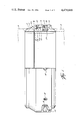
- FIG. 1 is an elevation view of the connector which is the subject of this invention, partially in section, which shows in particular one of the threaded screws for connecting the two sections rigidly together and the alignment pin and its cooperating slot;
- FIG. 2 is a partial sectional view similar to that of FIG. 1 which shows a different embodiment of the invention and particularly shows the alignment pin and slot and the cooperating surfaces between the pin and box sections which are partially coaxial with the pipe sections and partially tapered; and
- FIG. 3 is a sectional view similar to FIGS. 1 and 2 showing another embodiment of the invention where cooperating surfaces between the pin and box sections are coaxial with the length of pipe.
- FIG. 1 One preferred embodiment of the subject invention is shown in FIG. 1 where reference numeral 10 refers to a first end section formed as a pin which is adapted to be inserted into a second end section or box 12.
- the pin and box sections 10 and 12 together form a connector for adjacent lengths of pipe and, as shown by the brpoken lines in FIG. 1, are designed to be welded to elongated lengths of pipe 14.
- the box section 12 includes a tapered portion 12a and shoulder 16 formed on its inner surface which, when the joint is made-up, engage the cooperating tapered portion 10a and outer end 18 of the pin section.
- the cooperating surfaces after make-up, define the maximum penetration of the pin section 10 relative to the box section 12.
- the cooperating surfaces between the pin 10 and box 12 are formed so that when the pin 10 is inserted into the box 12, the tapered cooperating surfaces designated by reference numerals 10a and 12a, respectively, first engage each other leaving a slight gap between the pin end 18 and shoulder 16, significance of which is discussed below.
- the pin section 10 includes a plurality of threaded holes 24 spaced apart circumferentially around the outer surface of the pin section 10.
- a threaded latch screw 26 is located in each of the holes 24, the latch screw 26 being designed so that when the box section 12 is lowered into place onto the pin section 10, the latch screws 26 can be screwed into the holes 24 so that the outer ends of the latch screws 26 do not project beyond the outer surface of the pin section 10. In this way, the box section 12 can be lowered past the threaded latch screws 26 into the position shown in FIG. 1.
- a plurality of openings 28 extend through the box section 12 and are located to be in alignment with the threaded latch screws 26 when the pin section and box section have been stabbed as shown in FIG. 1.
- This alignment is assured by providing an alignment or guide pin 30 on the outer surface of the pin section 10 (see FIG. 2), the guide pin 30 cooperating with a slot 32 formed in the lower edge of the box section 12.
- the slot 32 is flared at its outer end and tapers to an opening slightly larger than the diameter of the alignment pin 30 to insure easy alignment between the openings 28 and the threaded latch screw 26.
- the flared outer end of the slot 32 makes it easier initially to align the slot with the guide pin 30 when the box section 12 is lowered in place.
- each latch screw 26 includes a wrench socket 34 located on the top which is accessible through the opening 28 or the socket 34 can extend through the entire length of the latch screws 26 as shown in FIGS. 2 and 3.
- the opening 28 and top portion of each latch screw 26 are formed with cooperating tapered surfaces which engage each other as the latch screw 26 is rotated and unscrewed to move into the opening 28 to the position shown in FIG. 1.
- the openings 28 are formed so that when the box section 12 overlaps the pin section 10 the latch screws 26 first engage the lower edge of the opening 28.
- the latch screws 26 When the latch screws 26 are unscrewed and move outwardly, they cause the outer end of the box section 12 to move slighty outwardly and downward closing the gap between the shoulder 16 and the pin section outer end 18 and preloading the connection by compressing the pin 10 both radially and longitudinally and placing the box 12 in tension between the shoulder 16 and the tapered surface 28.
- the latch screws 26 are simply rotated in the opposite direction until they are completely retracted into the holes 24, at which time the box section 12 can be removed from the pin section 10.
- the arrangement could be reversed where the latch screws 26 are carried by threaded holes formed in the box section 12 and screwed into tapered openings formed in the pin section 10 for forming the connection, but the configuration in FIG. 1 is preferred.
- a pair of seals in the form of O-rings 38 and 40 are provided as the primary and secondary seals, respectively, for the joint and are located in slots formed around the outer surface of the pin section 10.
- a test port 42a can be provided to receive a grease fitting so that the seals can be tested before being placed in service.
- the cooperating outer surface 10a of the pin section 10 and inner surface 12a of the box section 12 are tapered, although those surfaces may be partially tapered and partially coaxial with the pipe sections shown in FIG. 1.
- the embodiment shown in FIG. 1 can be used as a connector for joining lengths of relatively large diameter conductor pipe and for joining a subsea wellhead housing to the last joint of conductor pipe.
- the embodiment in FIG. 3, for example, can be used in connection with a jack-up drilling rig, from below the mud line to the rig.
- initial contact between the pin 10 and box 12 could be made between the box shoulder 16 and pin end 18, leaving a slight gap between the pin shoulder 42 and box shoulder 44. Tightening of the latch screws 26 would tension the box 12 and bring shoulders 42 and 44 in contact.
- the embodiment of FIG. 2 could be further modified so that initial contact is made between tapered portions 10a and 12a and a slight gap is formed between pin end 18 and shoulder 16 and between shoulders 42 and 44. Actuating the latch screws 26 would close these gaps and tension the box 12 as well as form a metal-to-metal seal between the tapered surfaces 10a and 12a which could be used in addition to or in lieu of O-ring seals 38 and 40.
- a coupling which can be adapted for use in connection with subsea conductor or surface casing on oil and gas wells.
- the coupling only has two major parts, a pin section and a box section which can be welded to adjacent lengths of large diameter pipe. After the box section is in place over the pin section, the two connector sections are easily connected by rotating a number of threaded latch screws which are retained in threaded openings in the outer surface of the pin section and which are accessible through openings extending through the box section.
- This connection is extremely strong and rigid and allows the pipes to be driven after the connection is formed.
- this connector is relatively inexpensive to manufacture.
Landscapes
- Engineering & Computer Science (AREA)
- General Engineering & Computer Science (AREA)
- Mechanical Engineering (AREA)
- Life Sciences & Earth Sciences (AREA)
- Geology (AREA)
- Mining & Mineral Resources (AREA)
- Physics & Mathematics (AREA)
- Environmental & Geological Engineering (AREA)
- Fluid Mechanics (AREA)
- General Life Sciences & Earth Sciences (AREA)
- Geochemistry & Mineralogy (AREA)
- Mutual Connection Of Rods And Tubes (AREA)
Abstract
Description
Claims (7)
Priority Applications (1)
| Application Number | Priority Date | Filing Date | Title |
|---|---|---|---|
| US06/364,392 US4479669A (en) | 1982-04-01 | 1982-04-01 | Pipe connector with threaded latch screws |
Applications Claiming Priority (1)
| Application Number | Priority Date | Filing Date | Title |
|---|---|---|---|
| US06/364,392 US4479669A (en) | 1982-04-01 | 1982-04-01 | Pipe connector with threaded latch screws |
Publications (1)
| Publication Number | Publication Date |
|---|---|
| US4479669A true US4479669A (en) | 1984-10-30 |
Family
ID=23434334
Family Applications (1)
| Application Number | Title | Priority Date | Filing Date |
|---|---|---|---|
| US06/364,392 Expired - Lifetime US4479669A (en) | 1982-04-01 | 1982-04-01 | Pipe connector with threaded latch screws |
Country Status (1)
| Country | Link |
|---|---|
| US (1) | US4479669A (en) |
Cited By (20)
| Publication number | Priority date | Publication date | Assignee | Title |
|---|---|---|---|---|
| US4693500A (en) * | 1985-06-07 | 1987-09-15 | David Anderson | Swivel joint |
| US4799714A (en) * | 1986-04-28 | 1989-01-24 | Collet James R | Sleeve type casing head adapter |
| GB2263518A (en) * | 1992-01-21 | 1993-07-28 | Thomas David Shon Littlewood | Joining of two members |
| US20020183209A1 (en) * | 2001-06-04 | 2002-12-05 | Halla Climate Control Corporation | Method for forming solid film lubricant |
| US20040174015A1 (en) * | 2003-03-03 | 2004-09-09 | Price Brothers Company | Testable pipe joint |
| EP1591413A1 (en) * | 2004-04-30 | 2005-11-02 | Delaware Capital Formation, Inc. | Drop tube insert and apparatus adapted for use with a riser pipe |
| US20050241696A1 (en) * | 2004-04-30 | 2005-11-03 | Kane Kristopher A | Drop tube segments adapted for use with a liquid reservoir |
| US20050241695A1 (en) * | 2004-04-30 | 2005-11-03 | Pendleton David R | Drop tube segments adapted for use with a liquid reservoir and methods |
| US20050241722A1 (en) * | 2004-04-30 | 2005-11-03 | Pendleton David R | Drop tube segments adapted for use with a liquid reservoir |
| US20050254910A1 (en) * | 2004-04-30 | 2005-11-17 | Kane Kristopher A | Systems adapted to cooperate with an aperture forming tool and methods |
| US20070049093A1 (en) * | 2004-05-20 | 2007-03-01 | Otten Gregory K | Anti-Rotation Device for Mating Connectors and Methods of Using Same |
| US20080157521A1 (en) * | 2007-01-03 | 2008-07-03 | Davis Joseph S | Anchor pile coupling system |
| USRE43773E1 (en) * | 1998-06-09 | 2012-10-30 | Seaboard International Inc. | Drilling quick connectors |
| US20140353045A1 (en) * | 2011-09-13 | 2014-12-04 | Atlas Copco Canada Inc. | Drill pipe with replaceable tool joints |
| WO2014164209A3 (en) * | 2013-03-11 | 2014-12-11 | Bp Corporation North America Inc. | Riser breakaway connection and intervention coupling device |
| US10041308B2 (en) * | 2015-12-09 | 2018-08-07 | Nabors Drilling Technologies Usa, Inc. | Oilfield tubular connection system and method |
| US20200271163A1 (en) * | 2017-09-08 | 2020-08-27 | Sew-Eurodrive Gmbh & Co. Kg | Assembly for connecting an adapter shaft to a shaft in a force-fitting manner using a clamping ring |
| US11015400B2 (en) * | 2016-08-31 | 2021-05-25 | Deltatek Oil Tools, Ltd. | Apparatus for transmitting torque through a work string |
| US11193337B1 (en) * | 2016-11-21 | 2021-12-07 | Pruitt Tool & Supply Co. | Method and device for connecting to a conductor pipe |
| US20220356970A1 (en) * | 2015-04-16 | 2022-11-10 | Krzysztof Jan Wajnikonis | Mechanical connector utilizing shear pins to transfer torque |
Citations (3)
| Publication number | Priority date | Publication date | Assignee | Title |
|---|---|---|---|---|
| US3183024A (en) * | 1962-03-13 | 1965-05-11 | Jack A Myers | Radial wedge joint |
| US3472538A (en) * | 1968-02-28 | 1969-10-14 | Pan American Petroleum Corp | Joint for coupling two tubular members together |
| US4124231A (en) * | 1977-05-04 | 1978-11-07 | Vetco, Inc. | Rigid pipe connector with radially shiftable lock elements and method of making the same |
-
1982
- 1982-04-01 US US06/364,392 patent/US4479669A/en not_active Expired - Lifetime
Patent Citations (3)
| Publication number | Priority date | Publication date | Assignee | Title |
|---|---|---|---|---|
| US3183024A (en) * | 1962-03-13 | 1965-05-11 | Jack A Myers | Radial wedge joint |
| US3472538A (en) * | 1968-02-28 | 1969-10-14 | Pan American Petroleum Corp | Joint for coupling two tubular members together |
| US4124231A (en) * | 1977-05-04 | 1978-11-07 | Vetco, Inc. | Rigid pipe connector with radially shiftable lock elements and method of making the same |
Cited By (35)
| Publication number | Priority date | Publication date | Assignee | Title |
|---|---|---|---|---|
| US4693500A (en) * | 1985-06-07 | 1987-09-15 | David Anderson | Swivel joint |
| US4799714A (en) * | 1986-04-28 | 1989-01-24 | Collet James R | Sleeve type casing head adapter |
| GB2263518A (en) * | 1992-01-21 | 1993-07-28 | Thomas David Shon Littlewood | Joining of two members |
| GB2263518B (en) * | 1992-01-21 | 1995-06-07 | Thomas David Shon Littlewood | Joining two members |
| USRE43773E1 (en) * | 1998-06-09 | 2012-10-30 | Seaboard International Inc. | Drilling quick connectors |
| US20020183209A1 (en) * | 2001-06-04 | 2002-12-05 | Halla Climate Control Corporation | Method for forming solid film lubricant |
| EP1273847A1 (en) * | 2001-06-04 | 2003-01-08 | Halla Climate Control Corporation | Method for forming solid film lubricant |
| US6815400B2 (en) | 2001-06-04 | 2004-11-09 | Halla Climate Control Corp. | Method for forming solid film lubricant |
| US7118137B2 (en) * | 2003-03-03 | 2006-10-10 | Price Brothers Company | Testable pipe joint |
| US20040174015A1 (en) * | 2003-03-03 | 2004-09-09 | Price Brothers Company | Testable pipe joint |
| EP1591413A1 (en) * | 2004-04-30 | 2005-11-02 | Delaware Capital Formation, Inc. | Drop tube insert and apparatus adapted for use with a riser pipe |
| US20050241695A1 (en) * | 2004-04-30 | 2005-11-03 | Pendleton David R | Drop tube segments adapted for use with a liquid reservoir and methods |
| US20050241722A1 (en) * | 2004-04-30 | 2005-11-03 | Pendleton David R | Drop tube segments adapted for use with a liquid reservoir |
| US20050254910A1 (en) * | 2004-04-30 | 2005-11-17 | Kane Kristopher A | Systems adapted to cooperate with an aperture forming tool and methods |
| US7069965B2 (en) | 2004-04-30 | 2006-07-04 | Delaware Capital Formation, Inc. | Drop tube inserts and apparatus adapted for use with a riser pipe |
| US20050241696A1 (en) * | 2004-04-30 | 2005-11-03 | Kane Kristopher A | Drop tube segments adapted for use with a liquid reservoir |
| US7128102B2 (en) | 2004-04-30 | 2006-10-31 | Delaware Capital Formation, Inc. | Drop tube segments adapted for use with a liquid reservoir |
| US7213610B2 (en) | 2004-04-30 | 2007-05-08 | Delaware Capital Formation, Inc. | Drop tube segments adapted for use with a liquid reservoir and methods |
| US7243675B2 (en) | 2004-04-30 | 2007-07-17 | Delaware Capital Formation, Inc. | Drop tube segments adapted for use with a liquid reservoir |
| US20050241723A1 (en) * | 2004-04-30 | 2005-11-03 | Pendleton David R | Drop tube inserts and apparatus adapted for use with a riser pipe |
| US7437815B2 (en) | 2004-04-30 | 2008-10-21 | Delaware Capital Formation, Inc. | Systems adapted to cooperate with an aperture forming tool and methods |
| CN1693165B (en) * | 2004-04-30 | 2010-12-15 | 特拉华资本构成公司 | Drop tube inserts and apparatus adapted for use with a riserpipe |
| US20070049093A1 (en) * | 2004-05-20 | 2007-03-01 | Otten Gregory K | Anti-Rotation Device for Mating Connectors and Methods of Using Same |
| US7854451B2 (en) * | 2007-01-03 | 2010-12-21 | Davis Ii Joseph S | Anchor pile coupling system |
| US20080157521A1 (en) * | 2007-01-03 | 2008-07-03 | Davis Joseph S | Anchor pile coupling system |
| US20140353045A1 (en) * | 2011-09-13 | 2014-12-04 | Atlas Copco Canada Inc. | Drill pipe with replaceable tool joints |
| WO2014164209A3 (en) * | 2013-03-11 | 2014-12-11 | Bp Corporation North America Inc. | Riser breakaway connection and intervention coupling device |
| US9260931B2 (en) | 2013-03-11 | 2016-02-16 | Bp Corporation North America Inc. | Riser breakaway connection and intervention coupling device |
| US20220356970A1 (en) * | 2015-04-16 | 2022-11-10 | Krzysztof Jan Wajnikonis | Mechanical connector utilizing shear pins to transfer torque |
| US11739595B2 (en) * | 2015-04-16 | 2023-08-29 | Krzysztof Jan Wajnikonis | Mechanical connector utilizing shear pins to transfer torque |
| US10041308B2 (en) * | 2015-12-09 | 2018-08-07 | Nabors Drilling Technologies Usa, Inc. | Oilfield tubular connection system and method |
| US11015400B2 (en) * | 2016-08-31 | 2021-05-25 | Deltatek Oil Tools, Ltd. | Apparatus for transmitting torque through a work string |
| US11193337B1 (en) * | 2016-11-21 | 2021-12-07 | Pruitt Tool & Supply Co. | Method and device for connecting to a conductor pipe |
| US20200271163A1 (en) * | 2017-09-08 | 2020-08-27 | Sew-Eurodrive Gmbh & Co. Kg | Assembly for connecting an adapter shaft to a shaft in a force-fitting manner using a clamping ring |
| US11614124B2 (en) * | 2017-09-08 | 2023-03-28 | Sew-Eurodrive Gmbh & Co. Kg | Assembly for connecting an adapter shaft to a shaft in a force-fitting manner using a clamping ring |
Similar Documents
| Publication | Publication Date | Title |
|---|---|---|
| US4479669A (en) | Pipe connector with threaded latch screws | |
| US4830408A (en) | Connector assembly | |
| US4330140A (en) | Marine riser connector | |
| US4097069A (en) | Marine riser connector | |
| US4796923A (en) | Joints for tubular members | |
| US5810401A (en) | Threaded tool joint with dual mating shoulders | |
| US4522431A (en) | Self-aligning connector assembly | |
| RU2369721C2 (en) | Adapter of blowout preventer stuffing box | |
| US9957767B2 (en) | Multi-component C-ring coupling | |
| US5423575A (en) | Concentric riser joint with self-aligning coupling | |
| US8662188B2 (en) | Wired drill pipe cable connector system | |
| GB2119466A (en) | Pipe connector | |
| US20080238094A1 (en) | Oilfield Threaded Connection | |
| RU2550992C1 (en) | Detachable joint of long-length flexible pipe | |
| US20070257486A1 (en) | Elastomeric Seal for Expandable Connector | |
| US4407527A (en) | Self-aligning connector assembly | |
| US11428054B2 (en) | Mechanical coupling of tubulars | |
| CA3096724C (en) | Lobular connection for tubulars | |
| US10184303B2 (en) | Anti-rotation device for connector assembly and method | |
| CA1074225A (en) | Marine riser connector | |
| GB2559888A (en) | System and method |
Legal Events
| Date | Code | Title | Description |
|---|---|---|---|
| AS | Assignment |
Owner name: HYDRIL COMPANY, A CORP. OF DE. Free format text: ASSIGNMENT OF ASSIGNORS INTEREST.;ASSIGNOR:HYNES, JOSEPH H.;REEL/FRAME:004014/0691 Effective date: 19820318 |
|
| STCF | Information on status: patent grant |
Free format text: PATENTED CASE |
|
| FEPP | Fee payment procedure |
Free format text: PAYOR NUMBER ASSIGNED (ORIGINAL EVENT CODE: ASPN); ENTITY STATUS OF PATENT OWNER: LARGE ENTITY |
|
| FPAY | Fee payment |
Year of fee payment: 4 |
|
| FPAY | Fee payment |
Year of fee payment: 8 |
|
| FPAY | Fee payment |
Year of fee payment: 12 |
|
| AS | Assignment |
Owner name: CHASE BANK OF TEXAS, NATIONAL ASSOC., AS AGENT, TE Free format text: SECURITY INTEREST;ASSIGNOR:HYDRIL COMPANY;REEL/FRAME:009123/0016 Effective date: 19980323 |
|
| AS | Assignment |
Owner name: HYDRIL COMPANY, TEXAS Free format text: RELEASE OF LIEN;ASSIGNOR:CHASE BANK OF TEXAS, NATIONAL ASSOCIATION;REEL/FRAME:014734/0860 Effective date: 20040604 |