EP1591193A2 - Device for automatically supplying and evacuating vehicle subassemblies in assembling stations - Google Patents
Device for automatically supplying and evacuating vehicle subassemblies in assembling stations Download PDFInfo
- Publication number
- EP1591193A2 EP1591193A2 EP05006976A EP05006976A EP1591193A2 EP 1591193 A2 EP1591193 A2 EP 1591193A2 EP 05006976 A EP05006976 A EP 05006976A EP 05006976 A EP05006976 A EP 05006976A EP 1591193 A2 EP1591193 A2 EP 1591193A2
- Authority
- EP
- European Patent Office
- Prior art keywords
- shuttle
- station
- assemblies
- assembly
- stations
- Prior art date
- Legal status (The legal status is an assumption and is not a legal conclusion. Google has not performed a legal analysis and makes no representation as to the accuracy of the status listed.)
- Withdrawn
Links
Images


Classifications
-
- B—PERFORMING OPERATIONS; TRANSPORTING
- B23—MACHINE TOOLS; METAL-WORKING NOT OTHERWISE PROVIDED FOR
- B23P—METAL-WORKING NOT OTHERWISE PROVIDED FOR; COMBINED OPERATIONS; UNIVERSAL MACHINE TOOLS
- B23P19/00—Machines for simply fitting together or separating metal parts or objects, or metal and non-metal parts, whether or not involving some deformation; Tools or devices therefor so far as not provided for in other classes
- B23P19/001—Article feeders for assembling machines
-
- B—PERFORMING OPERATIONS; TRANSPORTING
- B23—MACHINE TOOLS; METAL-WORKING NOT OTHERWISE PROVIDED FOR
- B23P—METAL-WORKING NOT OTHERWISE PROVIDED FOR; COMBINED OPERATIONS; UNIVERSAL MACHINE TOOLS
- B23P21/00—Machines for assembling a multiplicity of different parts to compose units, with or without preceding or subsequent working of such parts, e.g. with programme control
- B23P21/008—Machines for assembling a multiplicity of different parts to compose units, with or without preceding or subsequent working of such parts, e.g. with programme control the assembling machines or tools moving synchronously with the units while these are being assembled
-
- B—PERFORMING OPERATIONS; TRANSPORTING
- B62—LAND VEHICLES FOR TRAVELLING OTHERWISE THAN ON RAILS
- B62D—MOTOR VEHICLES; TRAILERS
- B62D65/00—Designing, manufacturing, e.g. assembling, facilitating disassembly, or structurally modifying motor vehicles or trailers, not otherwise provided for
- B62D65/02—Joining sub-units or components to, or positioning sub-units or components with respect to, body shell or other sub-units or components
- B62D65/18—Transportation, conveyor or haulage systems specially adapted for motor vehicle or trailer assembly lines
-
- B—PERFORMING OPERATIONS; TRANSPORTING
- B23—MACHINE TOOLS; METAL-WORKING NOT OTHERWISE PROVIDED FOR
- B23P—METAL-WORKING NOT OTHERWISE PROVIDED FOR; COMBINED OPERATIONS; UNIVERSAL MACHINE TOOLS
- B23P2700/00—Indexing scheme relating to the articles being treated, e.g. manufactured, repaired, assembled, connected or other operations covered in the subgroups
- B23P2700/50—Other automobile vehicle parts, i.e. manufactured in assembly lines
Definitions
- the invention relates to a device for automatically feeding and discharging Vehicle assemblies at placement stations with a transfer device for Assemblies of stations for the provision of bare modules for Assembly station and for populated assemblies from the assembly station a station for the storage of populated assemblies.
- a transfer device for Assemblies of stations for the provision of bare modules for Assembly station and for populated assemblies from the assembly station a station for the storage of populated assemblies.
- Such devices are needed for factory automation in the automotive industry.
- the component conveyor is designed as a circular encircling conveyor that the transfer of the components takes place in the joining station by a movable transport device integrated in the joining station and in that the transport device has a plurality of coordinated trolley.
- the object of the invention is therefore to provide a technical Solution that helps with the shortcomings of the known art be overcome.
- a mounting device is to be developed which should be cost-effective to implement and the vast variability does not restrict the joining station to be supplied.
- a high Productivity of the joining station can be ensured.
- the Stations for the provision of bare assemblies and for filing populated assemblies can fulfill interface functions by acting as Buffers between the upstream and downstream processes act.
- a device for automatic supply and removal of motor vehicle assemblies at equipping stations from a separate lane for the Subrack from a transfer device for modules of stations for the provision of bare assemblies to the assembly station and for the transfer of populated assemblies from the assembly station to a station for the storage of populated assemblies.
- a shuttle arranged between the assembly station and the Stations for the provision of unpopulated assemblies and for storage assembled modules.
- the shuttle is on one arranged on a single carriageway and equipped with its own drive.
- the shuttle also has a synchronization device, with their Help the synchronization of the shuttle with the equipment of the equipping station will be produced.
- the shuttle has a manipulator for Positioning of the subrack.
- the manipulator with facilities equipped for the three-dimensional movement of the subrack can he programatically selects the subracks from the station for the program Provide unpopulated assemblies on the shuttle position, place on the placement station, from the placement station remove the assembled racks and finally at the station for the storage of stocked assemblies passed to this.
- the manipulator is at least in its parallel to the carriageway of the shuttle possible direction of movement Facilities equipped for fine synchronization.
- Subracks between the assembly carriage of the assembly station and to arrange the shuttle a transfer area. Only in this area is It then provided subracks from the shuttle to the equipping station to pass or through the manipulator of the placement station to decrease.
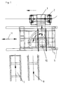
- FIG. 1 is in the context of a nest assembly between a Assembly station 1 and the station 7 for the provision of unpopulated Assemblies and the station 8 for the storage of assembled modules a shuttle 5 arranged for the transport and the transfer of the subrack 3.
- the Lane 6 of the shuttle and the lane 4 of the rack 3 in the Be Cultureungsstaion 1 are executed at least in the transfer area 11 in parallel.
- On the shuttle 5 is a manipulator 10 for positioning the Subrack 3 is arranged.
- This manipulator 10 enables the three-dimensional movement of the Subrack 3 in the transfer processes from and to the assembly carriage. 2 the loading station 1 and the station 7 for providing unpopulated Assemblies 3 on the shuttle 5 and from the shuttle 5 to the station 8 for the Storage of assembled modules. Both the drive of the shuttle 5 for the Transport of the developer 3 and the manipulator 10 for positioning of the Subrack 3 on the shuttle 5 are with synchronization devices. 9 fitted.
- the process takes place in that first the shuttle 5 at the station 7 for the provision of unpopulated assemblies a rack 3 with the help of the manipulator 10 takes over. The shuttle 5 is then in the transfer area 11 with the movement of the assembly vehicle. 2 the placement station 1 synchronized.
Landscapes
- Engineering & Computer Science (AREA)
- Mechanical Engineering (AREA)
- Manufacturing & Machinery (AREA)
- Chemical & Material Sciences (AREA)
- Combustion & Propulsion (AREA)
- Transportation (AREA)
- Automatic Assembly (AREA)
- Automobile Manufacture Line, Endless Track Vehicle, Trailer (AREA)
Abstract
Description
Die Erfindung betrifft eine Vorrichtung zum automatischen Zu- und Abführen von Kfz-Baugruppen an Bestückungsstationen mit einer Übergabevorrichtung für Baugruppen von Stationen für die Bereitstellung unbestückter Baugruppen zur Bestückungsstation und für bestückte Baugruppen von der Bestückungsstation zu einer Station für die Ablage bestückter Baugruppen. Derartige Vorrichtungen werden für die Fabrikautomatisierung in der Kfz-Industrie benötigt.The invention relates to a device for automatically feeding and discharging Vehicle assemblies at placement stations with a transfer device for Assemblies of stations for the provision of bare modules for Assembly station and for populated assemblies from the assembly station a station for the storage of populated assemblies. Such devices are needed for factory automation in the automotive industry.
In der Kranfahrzeugindusthe setzt sich im Zuge der Fabrikautomation zunehmend
die automatisierte Nestfertigung durch, mit der die teilautomatisierten
Montagelinien ergänzt werden.
Mit der DE 43 13 407 C2 wird eine Montageanlage zum automatischen Fügen
von vormontierten Bauteilen in Fahrzeugkarosserien beschrieben. Mit dieser
technischen Lösung sollen die Nachteile des bis dahin bekannten Standes der
Technik dadurch überwunden werden, daß zwischen der Fügestation und dem
Bereitstellungsraum für vormontierte Bauteile ein Bauteilförderer angeordnet ist.
Der Bauteilförderer übergibt dabei im mit der bewegten Fügestation
synchronisierten Zustand das vormontierte Bauteil in die Fügestation. Der
Nachteil dieser technischen Lösung besteht insbesondere darin, daß der
Bauteilförderer als kreisförmig umlaufender Förderer ausgebildet ist, daß die
Übergabe der Bauteile in die Fügestation durch eine in die Fügestation integrierte
bewegliche Transportvorrichtung erfolgt und daß die Transportvorrichtung
mehrere zu koordinierende Fahrwagen aufweist. In the crane vehicle industry, automated nest production, which supplements the semi-automated assembly lines, is increasingly gaining ground as part of factory automation.
With DE 43 13 407 C2 an assembly system for automatically joining pre-assembled components in vehicle bodies is described. With this technical solution, the disadvantages of the hitherto known state of the art are to be overcome by arranging a component conveyor between the joining station and the staging area for preassembled components. The component conveyor transfers in the synchronized with the moving joining station state, the pre-assembled component in the joining station. The disadvantage of this technical solution is, in particular, that the component conveyor is designed as a circular encircling conveyor that the transfer of the components takes place in the joining station by a movable transport device integrated in the joining station and in that the transport device has a plurality of coordinated trolley.
Die Aufgabe der Erfindung besteht deshalb in der Schaffung einer technischen Lösung, mit deren Hilfe die Mängel des bekannten Standes der Technik überwunden werden. Insbesondere soll eine Montagevorrichtung entwickelt werden, die kostengünstig realisierbar sein soll und die weitgehende Variabilität der zu versorgenden Fügestation nicht einschränkt. Außerdem soll durch einen zu gewährleistenden unterbrechungsfreien Betrieb der Fügestation eine hohe Produktivität der Fügestation sichergestellt werden. Außerdem sollen die Stationen für die Bereitstellung unbestückter Baugruppen und für die Ablage bestückter Baugruppen Schnittstellenfunktionen erfüllen können, indem sie als Puffer zwischen den vor- und nachgeschalteten Prozessen fungieren.The object of the invention is therefore to provide a technical Solution that helps with the shortcomings of the known art be overcome. In particular, a mounting device is to be developed which should be cost-effective to implement and the vast variability does not restrict the joining station to be supplied. In addition, should by a too ensuring uninterrupted operation of the joining station a high Productivity of the joining station can be ensured. In addition, the Stations for the provision of bare assemblies and for filing populated assemblies can fulfill interface functions by acting as Buffers between the upstream and downstream processes act.
Danach besteht eine Vorrichtung zum automatischen Zu- und Abführen von Kfz-Baugruppen an Bestückungsstationen aus einer eigenen Fahrbahn für die Baugruppenträger, aus einer Übergabevorrichtung für Baugruppen von Stationen für die Bereitstellung unbestückter Baugruppen zur Bestückungsstation und für die Übergabe bestückter Baugruppen von der Bestückungsstation zu einer Station für die Ablage bestückter Baugruppen. Zwischen der Bestückungsstation und den Stationen für die Bereitstellung unbestückter Baugruppen sowie für die Ablage bestückter Baugruppen ist hierbei ein Shuttle angeordnet. Der Shuttle ist auf einer einspurigen Fahrbahn angeordnet und mit einem eigenen Antrieb ausgestattet. Der Shuttle verfügt weiterhin über eine Synchronisationseinrichtung, mit deren Hilfe der Gleichlauf des Shuttles mit den Einrichtungen der Bestückungsstation hergestellt wird. Weiterhin verfügt der Shuttle über einen Manipulator zur Positionierung des Baugruppenträgers. Indem der Manipulator mit Einrichtungen für die dreidimensionale Bewegung des Baugruppenträgers ausgestattet ist, kann er die Baugruppenträger programmgesteuert wahlweise von der Station für die Bereitstellung unbestückter Baugruppen übernehmen, auf dem Shuttle positionieren, auf der Bestückungsstation ablegen, von der Bestückungsstation die bestückten Baugruppenträger abnehmen und diese schließlich an der Station für die Ablage bestückter augruppen an diese übergeben.Thereafter, there is a device for automatic supply and removal of motor vehicle assemblies at equipping stations from a separate lane for the Subrack, from a transfer device for modules of stations for the provision of bare assemblies to the assembly station and for the transfer of populated assemblies from the assembly station to a station for the storage of populated assemblies. Between the assembly station and the Stations for the provision of unpopulated assemblies and for storage assembled modules here is a shuttle arranged. The shuttle is on one arranged on a single carriageway and equipped with its own drive. The shuttle also has a synchronization device, with their Help the synchronization of the shuttle with the equipment of the equipping station will be produced. Furthermore, the shuttle has a manipulator for Positioning of the subrack. By the manipulator with facilities equipped for the three-dimensional movement of the subrack can he programatically selects the subracks from the station for the program Provide unpopulated assemblies on the shuttle position, place on the placement station, from the placement station remove the assembled racks and finally at the station for the storage of stocked assemblies passed to this.
In einer bevorzugten Ausführungsform ist der Manipulator wenigstens in seiner parallel zur Fahrbahn des Shuttles möglichen Bewegungsrichtung mit Einrichtungen für die Feinsynchronisation ausgestattet. In a preferred embodiment, the manipulator is at least in its parallel to the carriageway of the shuttle possible direction of movement Facilities equipped for fine synchronization.
Dies ermöglicht es, den Shuttle zunächst mittels seines synchronisierbaren Antriebs schnell auf etwa die erforderliche Geschwindigkeit der Bauträgerbewegung in der Bestückungsstation zu beschleunigen und danach die vollständige Synchronisation der Feinsynchronisation des auf dem Shuttle angeordneten Manipulators zu überlassen.This allows the shuttle first by means of its synchronizable Drive quickly to about the required speed Accelerate developer movement in the assembly station and then the full synchronization of the fine synchronization of the on the shuttle to leave arranged manipulator.
Bevorzugt ist es auch vorgesehen, für die Übergabe und Übernahme von Baugruppenträgern zwischen dem Montagewagen der Bestückungsstation und dem Shuttle einen Übergabebereich anzuordnen. Lediglich in diesem Bereich ist es danach vorgesehen, Baugruppenträger vom Shuttle auf die Bestückungsstation zu übergeben oder durch den Manipulator von der Bestückungsstation abzunehmen.Preferably, it is also provided for the transfer and takeover of Subracks between the assembly carriage of the assembly station and to arrange the shuttle a transfer area. Only in this area is It then provided subracks from the shuttle to the equipping station to pass or through the manipulator of the placement station to decrease.
Die Vorteile der Erfindung bestehen zusammengefaßt in der nun bestehenden
Möglichkeit der kostengünstigen Realisierung der Verknüpfung von Montage-oder
Fügestationen mit der vor- und nachgeschalteten Prozeßkette. Dies ist eine
unverzichtbare Voraussetzung für die effiziente Einfügung von Nestfertigungen in
die allgemeine Taktfertigung. Durch den Einsatz von Shuttles zwischen den
Schnittstellen zum übrigen Prozeß in Form der Station für die Bereitstellung
unbestückter Baugruppen und in Form der Station für die Ablage bestückter
Baugruppen wird die wünschenswerte Entkopplung erreicht, die zu einer
vergrößerten Redundanz der gesamten Prozeßkette beiträgt. Dies gestattet
maximale Auslastungsgrade der Kapazität der jeweiligen Fügestation, unabhängig
von zeitweiligen Störungen in den vor- und nachgeschalteten Prozeßstufen.
Mit der Dimensionierung der Aumahmcfähigkeit der Stationen für die
Bereitstellung unbestückter Baugruppen und für die Ablage bestückter
Baugruppen ist es möglich, die angestrebte Entkopplung und zugleich der
pufferwirkung des gesamten Fertigungsnestes zu gewährleisten.The advantages of the invention are summarized in the now existing possibility of cost-effective implementation of the linkage of assembly or joining stations with the upstream and downstream process chain. This is an indispensable prerequisite for the efficient insertion of nesting production into general cycle production. The use of shuttles between the interfaces to the rest of the process in the form of the station for the provision of bare assemblies and in the form of the station for the storage of populated assemblies, the desirable decoupling is achieved, which contributes to increased redundancy of the entire process chain. This allows maximum utilization levels of the capacity of the respective joining station, regardless of temporary disturbances in the upstream and downstream process stages.
With the dimensioning of the Aumahmcfähigkeit the stations for the provision of unpopulated assemblies and for filing populated assemblies, it is possible to ensure the desired decoupling and at the same time the buffer effect of the entire production nest.
Die Erfindung soll nachstehend mit Ausführungsbeispielen näher erläutert
werden.
In der beigefügten Zeichnung zeigen:
- Fig. 1
- die schematische Draufsicht eines zwischen dem Montagewagen der Fügestation und den Stationen für die Bereitstellung unbestückter Baugruppen und für die Ablage bestückter Baugruppen angeordneten Shuttles;
- Fig. 2
- die schematische Draufsicht eines Baugruppenträgers bei der Übernahme von der Station unbestückter Baugruppen auf den Shuttle;
- Fig. 3
- die scheinatische Draufsicht eines Baugruppenträgers nach erfolgter Synchronisation von Shuttle und Montagewagen bei der Übergabe vom Shuttle auf den Montagewagen;
- Fig. 4
- die schematische Draufsicht auf die gesamte Vorrichtung nach erfolgter Grobsynchronisation vor der Übernahme des Baugruppenträgers vom Montagewagen der Fügestation auf den Shuttle;
- Fig. 5
- die schematische Draufsicht auf den bestückten Baugruppenträger bei der Übergabe vom Shuttle auf die Station für die Ablage bestückter Baugruppenträger.
In the attached drawing show:
- Fig. 1
- the schematic plan view of an arranged between the assembly carriage of the joining station and the stations for the provision of unpopulated assemblies and for filing components assembled shuttles;
- Fig. 2
- the schematic plan view of a rack in the acquisition of the station unpopulated assemblies on the shuttle;
- Fig. 3
- the apparent top view of a subrack after synchronization of shuttle and assembly car in the transfer of the shuttle on the assembly carriage;
- Fig. 4
- the schematic plan view of the entire device after coarse synchronization before the acquisition of the rack from the assembly carriage of the joining station on the shuttle;
- Fig. 5
- the schematic plan view of the assembled rack when transferring from the shuttle to the station for filing stocked rack.
Gemäß der Figuren 1 bis 5 ist im Rahmen einer Nestmontage zwischen einer
Bestückungsstation 1 und der Station 7 für die Bereitstellung unbestückter
Baugruppen und der Station 8 für die Ablage bestückter Baugruppen ein Shuttle 5
für den Transport und die Übergabe der Baugruppenträgers 3 angeordnet. Die
Fahrbahn 6 des Shuttles und die Fahrbahn 4 des Baugruppenträgers 3 in der
Bestückungsstaion 1 sind zumindest im Übergabbereich 11 parallel ausgeführt.
Auf dem Shuttle 5 ist ein Manipulator 10 zur Positionierung des
Baugruppenträgers 3 angeordnet. According to the figures 1 to 5 is in the context of a nest assembly between a
Dieser Manipulator 10 ermöglicht die dreidimensionale Bewegung des
Baugruppenträgers 3 bei den Übergabeprozessen vom und zum Montagewagen 2
der Bestückungsstation 1 und von der Station 7 für Bereitstellung unbestückter
Baugruppen 3 auf den Shuttle 5 sowie vom Shuttle 5 auf die Station 8 für die
Ablage bestückter Baugruppen. Sowohl der Antrieb des Shuttles 5 für den
Transport des Bauträgers 3 als auch der Manipulator 10 zur Positionierung des
Baugruppenträgers 3 auf den Shuttle 5 sind mit Synchronisationseinrichtungen 9
ausgestattet. Im Ausführungsbeispiel erfolgt der Ablauf dadurch, daß zunächst
der Shuttle 5 an der Station 7 für die Bereitstellung unbestückter Baugruppen
einen Baugruppenträger 3 mit Hilfe des Manipulators 10 übernimmt. Der Shuttle
5 wird danach im Übergabebereich 11 mit der Bewegung des Montagewagens 2
der Bestückungsstation 1 synchronisiert. Danach erfolgt die Übergabe des
Baugruppenträgers 3 auf den Montagewagen 2 mit Hilfe des Manipulators 10.
Danach wird der Shuttle 5 im Übergabebereich 11 mit einem Montagewagen 2
synchronisiert, der eine in der Bestückungsstation 1 komplettierte Baugruppe
transportiert. Mit Hilfe des Manipulators 10 wird der Baugruppenträger 3 dieses
Montagewagens 2 vom Shuttle 5 übernommen und zur Station 8 für die Ablage
bestückter Baugruppen transportiert. Die Bestückungsstation 1 verfügt über
mehrere Montagewagen 2, die während dieser Prozeduren ununterbrochen
bewegt werden. Mit Hilfe des Shuttles 5 wird eine wirksame Entkopplung der
Nestfertigung in der Bestückungsstation 1 von den vor- und nachgelagerten
Prozessen erreicht.This
Gemäß der Figuren 1 bis 5 werden Baugruppenträger 3 zwischen Stationen 7 und
8 für die Bereitstellung unbestückter Baugruppen und für die Ablage bestückter
Baugruppen und dem Montagewagen 2 einer Bestückungsstation 1 mit Hilfe
eines Shuttles 5 bewegt. Der Antrieb des Shuttles 5 auf der Fahrbahn 6 verfügt
über eine Synchronisationseinrichtung 9 für die Grobsynchronisation der
Geschwindigkeiten des jeweiligen Montagewagens 2 der Bestückungsstation 1
auf der Fahrbahn 4 mit dem Shuttle 5. Nach dem Erreichen eines annähernden
Gleichlaufs erfolgt durch die Synchronisationseinrichtung 9 des Manipulators 10
zur Positionierung des Baugruppenträgers auf den Shuttle die Feinsynchronisation
des Bewegungsablaufs zwischen dem Montagewagen 2 der Bestückungsstation 1
und dem Manipulator 10. Hierbei läßt sich eine deutliche Beschleunigung des
Bewegungsablaufs und damit eine Verkürzung der Taktzeiten erreichen.According to the figures 1 to 5
- 11
- Bestückungsstationloading station
- 22
- Montagewagenassembly trolley
- 33
- Baugruppenträgerrack
- 44
- Fahrbahn des Baugruppenträgers in der BestückungsstationLane of the subrack in the assembly station
- 55
- Shuttle für den Transport des BaugruppenträgersShuttle for the transport of the subrack
- 66
- Fahrbahn des ShuttlesLane of the shuttle
- 77
- Station für die Bereitstellung unbestückter BaugruppenStation for the provision of bare assemblies
- 88th
- Station für die Ablage bestückter BaugruppenStation for the storage of assembled assemblies
- 99
- Synchronisationseinrichtungsynchronizer
- 1010
- Manipulator zur Positionierung des Baugruppenträgers auf dem ShuttleManipulator for positioning the subrack on the shuttle
- 1111
- ÜbergabebereichTransfer area
Claims (3)
daß der Shuttle (5) auf einer einlinigen Fahrbahn (6) positioniert ist,
daß der Shuttle (5) mit eigenem Antrieb ausgestattet ist,
daß der Shuttle (5) mit einer Synchonisationseinrichtung (9) ausgestattet ist daß auf dem Shuttle (5) ein Manipulator (10) zur Positionierung des Baugruppenträgers (3) angeordnet ist und
daß der Manipulator (10) mit Einrichtungen für die dreidimensionale Bewegung des Baugruppenträgers (3) ausgestattet ist.Device for the automatic supply and removal of motor vehicle assemblies at assembly stations (1) with its own roadway (4) for the subracks (3), with a transfer device for subassemblies of stations (7, 8) for providing unassembled subassemblies to the equipping station ( 1) and for populated assemblies of the assembly station (1) to a station (8) for the storage populated assemblies, characterized in that between the placement station, (1) and the stations (7, 8) for the provision of bare assemblies and for the filing of assembled assemblies is arranged a shuttle (5),
that the shuttle (5) is positioned on a single-line track (6),
that the shuttle (5) is equipped with its own drive,
in that the shuttle (5) is equipped with a synchronization device (9) that a manipulator (10) for positioning the module carrier (3) is arranged on the shuttle (5) and
in that the manipulator (10) is equipped with devices for the three-dimensional movement of the rack (3).
Applications Claiming Priority (2)
| Application Number | Priority Date | Filing Date | Title |
|---|---|---|---|
| DE200410020736 DE102004020736A1 (en) | 2004-04-27 | 2004-04-27 | Device for automatically feeding and removing vehicle assemblies at assembly stations |
| DE102004020736 | 2004-04-27 |
Publications (2)
| Publication Number | Publication Date |
|---|---|
| EP1591193A2 true EP1591193A2 (en) | 2005-11-02 |
| EP1591193A3 EP1591193A3 (en) | 2010-12-15 |
Family
ID=34934605
Family Applications (1)
| Application Number | Title | Priority Date | Filing Date |
|---|---|---|---|
| EP05006976A Withdrawn EP1591193A3 (en) | 2004-04-27 | 2005-03-31 | Device for automatically supplying and evacuating vehicle subassemblies in assembling stations |
Country Status (2)
| Country | Link |
|---|---|
| EP (1) | EP1591193A3 (en) |
| DE (1) | DE102004020736A1 (en) |
Cited By (1)
| Publication number | Priority date | Publication date | Assignee | Title |
|---|---|---|---|---|
| DE102013000569A1 (en) * | 2013-01-15 | 2014-07-17 | Audi Ag | Manufacturing plant for series production of motor vehicles, has multiple work stations at which predetermined working process is executable, where work stations are formed as separate and uncoupled workstations |
Families Citing this family (2)
| Publication number | Priority date | Publication date | Assignee | Title |
|---|---|---|---|---|
| DE102005061193B4 (en) * | 2005-12-21 | 2016-12-22 | Hermann Müller | Handling method and device, in particular on an injection molding machine |
| DE102014017957B4 (en) * | 2014-12-05 | 2018-01-04 | Lorenz Stöger | Device for feeding screws o. The like. Fasteners to a screwdriver or setting tool |
Citations (5)
| Publication number | Priority date | Publication date | Assignee | Title |
|---|---|---|---|---|
| US4674181A (en) * | 1980-06-18 | 1987-06-23 | Hitachi, Ltd. | Working/assembling system |
| DE3614165A1 (en) * | 1986-04-26 | 1987-10-29 | Kloeckner Humboldt Deutz Ag | Transport system for series productions |
| EP1110854A2 (en) * | 1999-12-23 | 2001-06-27 | Hyundai Motor Company | Robot system synchronized with conveyor speed and car seat providing method using such a robot system |
| EP1260469A1 (en) * | 2001-05-18 | 2002-11-27 | AUTEFA automation GmbH | Transferring apparatus for bottle treatment plants |
| EP1380392A2 (en) * | 2002-07-12 | 2004-01-14 | Finn-Power | A manufacturing cell, a transfer and manipulating apparatus and a positioning device |
-
2004
- 2004-04-27 DE DE200410020736 patent/DE102004020736A1/en not_active Withdrawn
-
2005
- 2005-03-31 EP EP05006976A patent/EP1591193A3/en not_active Withdrawn
Patent Citations (5)
| Publication number | Priority date | Publication date | Assignee | Title |
|---|---|---|---|---|
| US4674181A (en) * | 1980-06-18 | 1987-06-23 | Hitachi, Ltd. | Working/assembling system |
| DE3614165A1 (en) * | 1986-04-26 | 1987-10-29 | Kloeckner Humboldt Deutz Ag | Transport system for series productions |
| EP1110854A2 (en) * | 1999-12-23 | 2001-06-27 | Hyundai Motor Company | Robot system synchronized with conveyor speed and car seat providing method using such a robot system |
| EP1260469A1 (en) * | 2001-05-18 | 2002-11-27 | AUTEFA automation GmbH | Transferring apparatus for bottle treatment plants |
| EP1380392A2 (en) * | 2002-07-12 | 2004-01-14 | Finn-Power | A manufacturing cell, a transfer and manipulating apparatus and a positioning device |
Cited By (2)
| Publication number | Priority date | Publication date | Assignee | Title |
|---|---|---|---|---|
| DE102013000569A1 (en) * | 2013-01-15 | 2014-07-17 | Audi Ag | Manufacturing plant for series production of motor vehicles, has multiple work stations at which predetermined working process is executable, where work stations are formed as separate and uncoupled workstations |
| DE102013000569B4 (en) | 2013-01-15 | 2020-07-23 | Audi Ag | Manufacturing plant for the serial production of motor vehicles |
Also Published As
| Publication number | Publication date |
|---|---|
| DE102004020736A1 (en) | 2005-11-17 |
| EP1591193A3 (en) | 2010-12-15 |
Similar Documents
| Publication | Publication Date | Title |
|---|---|---|
| DE3409843C2 (en) | Method and system for producing workpieces consisting of several parts | |
| EP0203170B1 (en) | Flexible manufacturing system for the processing and production of multiple-component assemblies, in particular unfinished coachwork assemblies | |
| EP1601492B1 (en) | Manufacturing plant for parts, particularly vehicle body parts | |
| WO2007077056A1 (en) | Conveying system | |
| DE102007049221A1 (en) | Vehicle bodywork assembly plant, has holders for clamping-frames swinging about elevated axes, allowing frames to be transferred between loading- and presentation positions | |
| DE102019204612A1 (en) | Manufacturing station for processing components | |
| DE3341169C2 (en) | ||
| EP2166297B1 (en) | Transfer device for a freeze drying plant | |
| DE3229327A1 (en) | SUPPLY SYSTEM | |
| DE102018108436A1 (en) | Conveyor for an automated production line, component carrier for a conveyor and method for operating a conveyor | |
| DE102012009061A1 (en) | Processing plant for building units | |
| DE102007005029A1 (en) | Robot for use on locomotive workpiece carrier, has program enabling robot to process patterns or workpieces arranged on platform, and to transport patterns or workpieces to processing stations or to store on ground | |
| DE60121941T2 (en) | MANUFACTURING METHOD AND MANUFACTURING SYSTEM | |
| DD284638A5 (en) | FOUNDER DEVICE FOR ASSEMBLY INSTALLATIONS | |
| EP1591193A2 (en) | Device for automatically supplying and evacuating vehicle subassemblies in assembling stations | |
| DE4313407C2 (en) | Assembly system for automatic joining | |
| WO2018091450A1 (en) | Joining plant comprising a joining station and clamping frames | |
| DE102014009995A1 (en) | System and method for providing components within a production facility | |
| DE102004026088A1 (en) | Device for welding different body types | |
| EP3548215A2 (en) | Method for bonding large modules and corresponding bonding arrangement | |
| WO2016184677A1 (en) | Processing arrangement for processing assembly parts of an assembly on a processing station of a production line | |
| DE102013016826A1 (en) | Method and production system for joining different variants of raw modules | |
| DE102022119044A1 (en) | Device and method for producing product variants | |
| EP0365829B1 (en) | Transfer installation for cleaning and electroplating processes | |
| EP2113451B1 (en) | Method and device for producing motor vehicles |
Legal Events
| Date | Code | Title | Description |
|---|---|---|---|
| PUAI | Public reference made under article 153(3) epc to a published international application that has entered the european phase |
Free format text: ORIGINAL CODE: 0009012 |
|
| AK | Designated contracting states |
Kind code of ref document: A2 Designated state(s): AT BE BG CH CY CZ DE DK EE ES FI FR GB GR HU IE IS IT LI LT LU MC NL PL PT RO SE SI SK TR |
|
| AX | Request for extension of the european patent |
Extension state: AL BA HR LV MK YU |
|
| PUAL | Search report despatched |
Free format text: ORIGINAL CODE: 0009013 |
|
| AK | Designated contracting states |
Kind code of ref document: A3 Designated state(s): AT BE BG CH CY CZ DE DK EE ES FI FR GB GR HU IE IS IT LI LT LU MC NL PL PT RO SE SI SK TR |
|
| AX | Request for extension of the european patent |
Extension state: AL BA HR LV MK YU |
|
| AKX | Designation fees paid |
Designated state(s): AT BE BG CH CY CZ DE DK EE ES FI FR GB GR HU IE IS IT LI LT LU MC NL PL PT RO SE SI SK TR |
|
| STAA | Information on the status of an ep patent application or granted ep patent |
Free format text: STATUS: THE APPLICATION IS DEEMED TO BE WITHDRAWN |
|
| 18D | Application deemed to be withdrawn |
Effective date: 20110616 |