EP1590713B1 - Robot multi-axes equipe d'un systeme de commande - Google Patents
Robot multi-axes equipe d'un systeme de commande Download PDFInfo
- Publication number
- EP1590713B1 EP1590713B1 EP04707562A EP04707562A EP1590713B1 EP 1590713 B1 EP1590713 B1 EP 1590713B1 EP 04707562 A EP04707562 A EP 04707562A EP 04707562 A EP04707562 A EP 04707562A EP 1590713 B1 EP1590713 B1 EP 1590713B1
- Authority
- EP
- European Patent Office
- Prior art keywords
- bus
- arm
- robot according
- module
- robot
- Prior art date
- Legal status (The legal status is an assumption and is not a legal conclusion. Google has not performed a legal analysis and makes no representation as to the accuracy of the status listed.)
- Expired - Lifetime
Links
Images
Classifications
-
- G—PHYSICS
- G05—CONTROLLING; REGULATING
- G05B—CONTROL OR REGULATING SYSTEMS IN GENERAL; FUNCTIONAL ELEMENTS OF SUCH SYSTEMS; MONITORING OR TESTING ARRANGEMENTS FOR SUCH SYSTEMS OR ELEMENTS
- G05B19/00—Program-control systems
- G05B19/02—Program-control systems electric
- G05B19/18—Numerical control [NC], i.e. automatically operating machines, in particular machine tools, e.g. in a manufacturing environment, so as to execute positioning, movement or co-ordinated operations by means of program data in numerical form
- G05B19/414—Structure of the control system, e.g. common controller or multiprocessor systems, interface to servo, programmable interface controller
-
- B—PERFORMING OPERATIONS; TRANSPORTING
- B25—HAND TOOLS; PORTABLE POWER-DRIVEN TOOLS; MANIPULATORS
- B25J—MANIPULATORS; CHAMBERS PROVIDED WITH MANIPULATION DEVICES
- B25J9/00—Program-controlled manipulators
- B25J9/16—Program controls
- B25J9/1602—Program controls characterised by the control system, structure, architecture
-
- G—PHYSICS
- G05—CONTROLLING; REGULATING
- G05B—CONTROL OR REGULATING SYSTEMS IN GENERAL; FUNCTIONAL ELEMENTS OF SUCH SYSTEMS; MONITORING OR TESTING ARRANGEMENTS FOR SUCH SYSTEMS OR ELEMENTS
- G05B2219/00—Program-control systems
- G05B2219/30—Nc systems
- G05B2219/33—Director till display
- G05B2219/33162—Two bus, high speed and low speed bus, linked or not
-
- G—PHYSICS
- G05—CONTROLLING; REGULATING
- G05B—CONTROL OR REGULATING SYSTEMS IN GENERAL; FUNCTIONAL ELEMENTS OF SUCH SYSTEMS; MONITORING OR TESTING ARRANGEMENTS FOR SUCH SYSTEMS OR ELEMENTS
- G05B2219/00—Program-control systems
- G05B2219/30—Nc systems
- G05B2219/33—Director till display
- G05B2219/33218—Motor encoders, resolvers on common bus with drives, servo controllers
-
- G—PHYSICS
- G05—CONTROLLING; REGULATING
- G05B—CONTROL OR REGULATING SYSTEMS IN GENERAL; FUNCTIONAL ELEMENTS OF SUCH SYSTEMS; MONITORING OR TESTING ARRANGEMENTS FOR SUCH SYSTEMS OR ELEMENTS
- G05B2219/00—Program-control systems
- G05B2219/30—Nc systems
- G05B2219/40—Robotics, robotics mapping to robotics vision
- G05B2219/40237—Bus for communication with sensors
-
- Y—GENERAL TAGGING OF NEW TECHNOLOGICAL DEVELOPMENTS; GENERAL TAGGING OF CROSS-SECTIONAL TECHNOLOGIES SPANNING OVER SEVERAL SECTIONS OF THE IPC; TECHNICAL SUBJECTS COVERED BY FORMER USPC CROSS-REFERENCE ART COLLECTIONS [XRACs] AND DIGESTS
- Y02—TECHNOLOGIES OR APPLICATIONS FOR MITIGATION OR ADAPTATION AGAINST CLIMATE CHANGE
- Y02P—CLIMATE CHANGE MITIGATION TECHNOLOGIES IN THE PRODUCTION OR PROCESSING OF GOODS
- Y02P90/00—Enabling technologies with a potential contribution to greenhouse gas [GHG] emissions mitigation
- Y02P90/02—Total factory control, e.g. smart factories, flexible manufacturing systems [FMS] or integrated manufacturing systems [IMS]
-
- Y—GENERAL TAGGING OF NEW TECHNOLOGICAL DEVELOPMENTS; GENERAL TAGGING OF CROSS-SECTIONAL TECHNOLOGIES SPANNING OVER SEVERAL SECTIONS OF THE IPC; TECHNICAL SUBJECTS COVERED BY FORMER USPC CROSS-REFERENCE ART COLLECTIONS [XRACs] AND DIGESTS
- Y10—TECHNICAL SUBJECTS COVERED BY FORMER USPC
- Y10T—TECHNICAL SUBJECTS COVERED BY FORMER US CLASSIFICATION
- Y10T74/00—Machine element or mechanism
- Y10T74/20—Control lever and linkage systems
- Y10T74/20207—Multiple controlling elements for single controlled element
- Y10T74/20305—Robotic arm
-
- Y—GENERAL TAGGING OF NEW TECHNOLOGICAL DEVELOPMENTS; GENERAL TAGGING OF CROSS-SECTIONAL TECHNOLOGIES SPANNING OVER SEVERAL SECTIONS OF THE IPC; TECHNICAL SUBJECTS COVERED BY FORMER USPC CROSS-REFERENCE ART COLLECTIONS [XRACs] AND DIGESTS
- Y10—TECHNICAL SUBJECTS COVERED BY FORMER USPC
- Y10T—TECHNICAL SUBJECTS COVERED BY FORMER US CLASSIFICATION
- Y10T74/00—Machine element or mechanism
- Y10T74/20—Control lever and linkage systems
- Y10T74/20207—Multiple controlling elements for single controlled element
- Y10T74/20305—Robotic arm
- Y10T74/20311—Robotic arm including power cable or connector
-
- Y—GENERAL TAGGING OF NEW TECHNOLOGICAL DEVELOPMENTS; GENERAL TAGGING OF CROSS-SECTIONAL TECHNOLOGIES SPANNING OVER SEVERAL SECTIONS OF THE IPC; TECHNICAL SUBJECTS COVERED BY FORMER USPC CROSS-REFERENCE ART COLLECTIONS [XRACs] AND DIGESTS
- Y10—TECHNICAL SUBJECTS COVERED BY FORMER USPC
- Y10T—TECHNICAL SUBJECTS COVERED BY FORMER US CLASSIFICATION
- Y10T74/00—Machine element or mechanism
- Y10T74/20—Control lever and linkage systems
- Y10T74/20207—Multiple controlling elements for single controlled element
- Y10T74/20305—Robotic arm
- Y10T74/20317—Robotic arm including electric motor
-
- Y—GENERAL TAGGING OF NEW TECHNOLOGICAL DEVELOPMENTS; GENERAL TAGGING OF CROSS-SECTIONAL TECHNOLOGIES SPANNING OVER SEVERAL SECTIONS OF THE IPC; TECHNICAL SUBJECTS COVERED BY FORMER USPC CROSS-REFERENCE ART COLLECTIONS [XRACs] AND DIGESTS
- Y10—TECHNICAL SUBJECTS COVERED BY FORMER USPC
- Y10T—TECHNICAL SUBJECTS COVERED BY FORMER US CLASSIFICATION
- Y10T74/00—Machine element or mechanism
- Y10T74/20—Control lever and linkage systems
- Y10T74/20207—Multiple controlling elements for single controlled element
- Y10T74/20341—Power elements as controlling elements
Definitions
- the invention relates to a multi-axis robot equipped with a control system.
- multi-axis robots can be controlled by supplying their electric motors with control signals generated from a computing and processing unit in which the trajectory of the robot is determined.
- a computing and processing unit in which the trajectory of the robot is determined.
- a large number of cables must be installed between the arm and its control unit, which induces significant connection and wiring times and significant risks of error leading to complex and expensive debugging operations.
- EP-A-0 777 167 It is known from EP-A-0 777 167 to use an optical fiber bus to connect a digital controller to amplifiers each connected to an encoder by a conventional line. These links between the amplifiers and the encoders make the installation of these devices long and complex.
- JP-A-10 178 437 provides for connecting encoders to an external computer via a bus, independently of the power portion of the installation.
- the invention intends to remedy more particularly by proposing a new architecture for a robot equipped with a control system that simplifies the manufacture of the controller, on the one hand, and the arm, on the other hand. , and the installation of this robot on its site of use.
- the invention aims also to improve the quality and speed of transfer of control and feedback signals.
- connection means comprise a single functional bus which connects a control unit associated with the computing and processing unit, on the one hand, to the power module (s) and on the other hand, at least one digital interface with at least one on-arm position sensor, this interface being integrated with the arm or located in its immediate vicinity.
- the feedback information relating to the position and speed of the moving parts of the robot as well as to the current consumed by the various motors are available for the calculation and processing unit at the frequency of the robot. bus.
- the digital signals transiting the bus in digital form are little disturbed by the ambient noise, at the difference of analog signals.
- An optimization of the trajectory control is obtained by the centralized processing of the servo loops.
- the use of the interface (s) is used to serialize or "serialize" information from digital sensors or to digitize and serialize information from analog sensors, and then pass it to the serial bus.
- the invention makes it possible to retain the advantages of a system that functionally centralizes trajectory generation and servocontrols.
- the interface (s) also makes it possible to calculate, as close as possible to the sensors or coders, the speeds and / or accelerations of the moving parts, at a frequency that is a multiple of that of the bus, which makes it possible to reduce the delay between position information, speed and / or acceleration, for better servocontrol.
- the fact of using a functional bus minimizes the number of conductive cables in the installation, in particular inside the arm, hence a better implementation of the connection cable or cables, lightened dimensional constraints for the elements of the arm , better accessibility to the elements included in this arm and ease of obtaining mobility of the arm because the minimum radius of curvature of the bus can be relatively low.
- the robot according to the invention is more economical to design and manufacture and can benefit from algorithms that make it faster and more accurate than those of the prior art.
- the single functional bus is broken down into at least two structural buses which connect, for the first, the control unit to the power module (s) and, for the second or second and subsequent, the control unit at the interface or interfaces.
- the first bus may be metallic, in particular made of copper, while another bus may, for example, be made of optical fibers, this type of bus being particularly immune to ambient electromagnetic noise and can be of great length while maintaining a high speed.
- the fact of using several structural buses makes it possible to circumvent the problem due to the limits of their bandwidth to add, if necessary, more elements or more information processed by element.
- control unit is connected to the computing and processing unit by a PCI type bus ("Peripheral Component Interconnect").
- PCI type bus Peripheral Component Interconnect
- control unit is integrated in the computing and processing unit.
- An identification and calibration card can be embarked on the arm or located in its immediate vicinity, this card being integrated into the bus. This makes it easy to download the parameters specific to the robot to the computing and processing unit. We can talk about "plug and play” connection.
- the or each structural bus may be adapted to be extended by complementary connection means to at least one external member, such as a seventh axis, in particular a conveyor axis, or any information processing member, such as a security.
- connection means may furthermore comprise a power conductor connecting the aforementioned module (s) to the robot, independently of the functional bus.
- the first structural bus is advantageously connected directly or indirectly to power modules each dedicated to a motor of the robot.
- the aforementioned interface is an interface card capable of calculating the speed and / or acceleration of the movement measured by the or each associated sensor, of serializing its output signal and, optionally, of digitizing the output signals of the sensor or sensors when they are analog.
- the interface in question is integrated in the associated sensor, with the same functions as above.
- the arm A of the robot R shown in the figure is arranged along a conveying path shown by a direction X-X '.
- This arm is provided with six motors each able to move a movable part of the arm around one of its six axes to move a tool O in space.
- These motors are represented by a motorization assembly 10 in the figure. In practice, they are distributed inside the arm A.
- Six analog sensors or position encoders 12 are distributed in the robot R and make it possible to measure the movements of the arm around each of its six axes.
- Three interface cards 14 are mounted on the arm A and are each associated with two sensors 12. Each card 14 makes it possible to digitize and serialize the analog output signal of a sensor or encoder 12. Each card 14 also makes it possible to calculate the first derivative and / or the second derivative of the signal thus generated, which makes it possible to determine the corresponding speed and / or acceleration for the mobile part of the robot R. As the cards 14 are located near the sensors or encoders 12, derivatives calculations can be performed with a high frequency, of the order of 20 kHz, while the information frames are transmitted at 10 kHz.
- the cards 14 may be, depending on the construction choices, integrated sensors 12, common to two sensors and distributed in the arm A, as shown, or arranged at the foot of the arm A.
- a single card can be the different cards 14 mentioned above.
- the robot R also includes a controller C for controlling the arm A, this controller comprising an envelope 20 in which are housed six power modules 22 supplied with current by a cable 24. Each module 22 is dedicated to one of the motors of the arm A, these six modules 22 being connected to the arm A by a first connecting cable 52, eighteen conductors.
- the motors of the subassembly 10 are three-phase motors and each module 22 is connected to the corresponding motor by three conductors.
- a calculation and processing unit 26 commonly called “CPU” is also arranged in the envelope 20 and is connected by a PCI bus 28 to a control card 30 provided with an interface 32.
- the card 30 may be integrated in the card 26.
- An external portable computer 60 may be connected via an Ethernet link 62 to the unit 26 for programming and / or visualization of its operating parameters.
- the unit 26 makes it possible to calculate the trajectory of the robot R and to generate control signals from each of the modules 22 which each control a motor of the subassembly 10. To control these modules 22, taking into account the actual behavior of the arm A, the assembly formed of elements 26 to 30 is connected by a single functional bus B, on the one hand, three cards 34 each controlling two modules 22 and, on the other hand, the three interface cards 14.
- the bus B is divided into two structural buses B 1 and B 2 .
- the bus B 1 made of copper and contained in the envelope 20, makes it possible to pass to the cards 34 the control signals of the modules 22 and thereby to control the motors of the subassembly 10. Information also circulates cards 34 to the card 30 through the bus B 1 .
- the second structural bus B 2 is formed by optical fibers and comprises a cable 54 connecting between the interface 32 and an identification and calibration card 16 mounted near the foot of the arm A, this card 16 being connected, in series, by the second bus B 2 to each of the cards 14.
- bus B 2 is made of optical fibers makes it possible to immunize it against the electromagnetic disturbances that may result from the operation of the motors of the subassembly 10 or the coders 12.
- the two structural buses B 1 and B 2 form a single functional bus B with which it interacts, through the card 30, to transmit or receive control signals.
- the transmission of information to the control card 30 is particularly rapid, in practice carried out with a periodicity of less than 100 microseconds.
- the information also travels rapidly between the elements 26 and 30, this through the PCI bus 28.
- the structural bus B 2 can be opened to integrate complementary connection means B ' 2 for the control of an external axis, such as a conveyor axis, with a module 22 ', two sensors 12' and an interface card 14 '.
- connection means B ' 1 may make it possible to connect bus B 1 to an interface card 14 "associated with a sensor 12", for example within a safety device.
- the invention gives the control system great flexibility to adapt to its working environment. In particular, it is not necessary to add cables to the link between the controller C and the arm A when the control of an external axis has to be added.
- the installation of the robot R and its control system is particularly easy because the information stored on the card 16 makes it possible to envisage a recognition of the robot R by the controller C during the connection of the bus B 2 between the interface 32 and this map 16.
- the invention makes it possible to substantially reduce the costs of designing, manufacturing and wiring the control system of a robot, while the information collected, in particular as regards the positions, speeds and accelerations of the moving parts of the robot, are available as quickly and more precisely than in the most powerful devices with a structurally centralized system with a parallel bus.
- the invention has been represented with a functional bus formed of two structural buses B 1 and B 2 .
- a single bus or, on the contrary, more than two structural buses can be provided.
- the invention is not limited to robots equipped with analog position sensors. It can be implemented with digital sensors, in which case the interface performed by the cards 14 of the example described can be integrated with each sensor.
- the identification and calibration card 16 can be provided in the controller C and not at the arm A, in which case the elements A and C are matched because it is the card 16 which allows the unit 26 of " recognize "arm A.
Landscapes
- Engineering & Computer Science (AREA)
- Automation & Control Theory (AREA)
- Human Computer Interaction (AREA)
- Manufacturing & Machinery (AREA)
- Physics & Mathematics (AREA)
- General Physics & Mathematics (AREA)
- Robotics (AREA)
- Mechanical Engineering (AREA)
- Manipulator (AREA)
- Numerical Control (AREA)
- Control Of Multiple Motors (AREA)
- Selective Calling Equipment (AREA)
Description
- L'invention a trait à un robot multi-axes équipé d'un système de commande.
- Il est connu que les robots multi-axes peuvent être commandés en fournissant à leurs moteurs électriques des signaux de commande générés à partir d'une unité de calcul et de traitement dans laquelle est déterminée la trajectoire du robot. Pour que le calcul de trajectoire soit efficace, il est connu, par exemple de US-A-4, 786, 847 de faire travailler l'unité précitée en boucle fermée, en utilisant des signaux de contre-réaction provenant de capteurs de position portés par le bras du robot. Dans les robots connus, un grand nombre de câbles doivent être installés entre le bras et son unité de commande, ce qui induit des temps de connexion et de câblage importants et des risques d'erreur non négligeables induisant des opérations de déboguage complexes et coûteuses.
- Il est connu de EP-A-0 777 167 d'utiliser un bus en fibres optiques pour connecter un contrôleur numérique à des amplificateurs reliés chacun à un codeur par une ligne classique. Ces liaisons entre les amplificateurs et les codeurs rend longue et complexe l'installation de ces matériels.
- Par ailleurs, JP-A-10 178 437 prévoit de relier par un bus des codeurs à un ordinateur externe et ce, indépendamment de la partie de puissance de l'installation.
- C'est à ces inconvénients qu'entend plus particulièrement remédier l'invention en proposant une nouvelle architecture pour un robot équipé d'un système de commande qui simplifie la fabrication du contrôleur, d'une part, et du bras, d'autre part, et l'installation de ce robot sur son site d'utilisation. L'invention vise également à améliorer la qualité et la vitesse de transfert des signaux de contrôle et de contre-réaction.
- Dans cet esprit, l'invention concerne un robot multi-axes comportant un bras apte à déplacer un outil dans l'espace et actionné par des moteurs électriques, ainsi qu'un système de commande comprenant :
- un contrôleur qui inclut au moins un module de puissance permettant l'alimentation en courant des moteurs et au moins une unité de calcul et de traitement permettant, notamment, le calcul de trajectoire du bras et la génération de signaux de contrôle du ou des modules précités ;
- des moyens de liaison entre le bras, le ou les modules de puissance et l'unité précitée, ces moyens de liaison permettant au moins l'alimentation des moteurs à partir du ou des modules de puissance et le contrôle de ce ou ces modules par l'unité de calcul et de traitement, ainsi que la transmission de signaux de contre-réaction du bras vers cette unité et/ou ce ou ces modules.
- Ce système est caractérisé en ce que les moyens de liaison précités comprennent un bus fonctionnel unique qui relie une unité de contrôle associée à l'unité de calcul et de traitement, d'une part, au(x) module(s) de puissance et, d'autre part, à au moins une interface numérique avec au moins un capteur de position embarqué sur le bras, cette interface étant intégrée au bras ou située dans son voisinage immédiat.
- Grâce à l'invention, les informations de contre-réaction relatives à la position et à la vitesse des éléments mobiles du robot ainsi qu'au courant consommé par les différents moteurs sont disponibles pour l'unité de calcul et de traitement à la fréquence du bus. En outre, les signaux numériques transitant dans le bus sous forme numérique sont peu perturbés par le bruit ambiant, à la différence de signaux analogiques. Une optimisation du contrôle de trajectoire est obtenue par le traitement centralisé des boucles d'asservissement. L'utilisation de la ou des interface(s) permet de mettre en série ou « sérialiser » des informations provenant de capteurs numériques ou de numériser et de sérialiser des informations provenant de capteurs analogiques, puis de les faire transiter vers le bus série. L'invention permet de conserver les avantages d'un système centralisant fonctionnellement la génération de trajectoire et les asservissements. La ou les interface(s) permet(tent) également de calculer, au plus près des capteurs ou codeurs, les vitesses et/ou accélérations des parties mobiles, à une fréquence multiple de celle du bus, ce qui permet de réduire le retard entre l'information de position, de vitesse et/ou d'accélération, en vue d'un meilleur asservissement. Le fait d'utiliser un bus fonctionnel minimise le nombre de câbles conducteurs dans l'installation, en particulier à l'intérieur du bras, d'où une meilleure implantation du ou des câbles de connexion, des contraintes dimensionnelles allégées pour les éléments du bras, une meilleure accessibilité aux éléments inclus dans ce bras et une facilité d'obtention de la mobilité de ce bras car le rayon de courbure minimum du bus peut être relativement faible. Le robot conforme à l'invention est plus économique à concevoir et à fabriquer et peut bénéficier d'algorithmes qui le rendent plus rapide et plus précis que ceux de l'art antérieur.
- Selon un aspect tout à fait avantageux de l'invention, le bus fonctionnel unique se décompose en au moins deux bus structurels qui relient, pour le premier, l'unité de contrôle au(x) module(s) de puissance et, pour le second ou les deuxième et suivants, l'unité de contrôle à l'interface ou aux interfaces. Le fait d'avoir au moins deux bus structurels distincts permet d'adapter chacun de ces bus au lieu dans lequel il est installé : le premier bus peut être métallique, notamment en cuivre, alors qu'un autre bus peut, par exemple, être en fibres optiques, ce type de bus étant particulièrement immunisé par rapport aux bruits électromagnétiques ambiants et pouvant être de grande longueur tout en conservant une grande rapidité. Le fait d'utiliser plusieurs bus structurels permet de contourner le problème dû aux limites de leur bande passante pour ajouter, en cas de besoin, plus d'éléments ou plus d'informations traitées par élément.
- De façon avantageuse, l'unité de contrôle est reliée à l'unité de calcul et de traitement par un bus de type PCI (« Peripheral Component Interconnect »). En variante, l'unité de contrôle est intégrée à l'unité de calcul et de traitement.
- Une carte d'identification et de calibration peut être embarquée sur le bras ou située dans son voisinage immédiat, cette carte étant intégrée au bus. Ceci permet de télécharger aisément vers l'unité de calcul et de traitement les paramètres propres au robot. On peut ainsi parler de connexion « plug and play ».
- Le ou chaque bus structurel peut être apte à être étendu par des moyens de connexion complémentaires à au moins un organe externe, tel qu'un septième axe, notamment un axe de convoyeur, ou tout organe traitant de l'information, comme un dispositif de sécurité.
- Les moyens de liaison peuvent comprendre, en outre, un conducteur de puissance reliant le ou les modules précités au robot, indépendamment du bus fonctionnel.
- Le premier bus structurel est avantageusement raccordé directement ou indirectement à des modules de puissance dédiés chacun à un moteur du robot. On peut, en outre, prévoir que l'interface précitée est une carte d'interface apte à calculer la vitesse et/ou l'accélération du mouvement mesuré par le ou chaque capteur associé, à sérialiser son signal de sortie et, éventuellement, à numériser préalablement les signaux de sortie du ou des capteurs lorsqu'ils sont analogiques. En variante, l'interface en question est intégrée au capteur associé, avec les mêmes fonctions que ci-dessus.
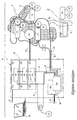
- L'invention sera mieux comprise et d'autres avantages de celle-ci apparaîtront plus clairement à la lumière de la description qui va suivre d'un mode de réalisation d'un robot multi-axes et de son système de commande conformes à l'invention, donné uniquement à titre d'exemple et faite en référence au dessin annexé dans lequel la figure unique est une représentation schématique de principe d'un système de commande et d'un robot multi-axes associés.
- Le bras A du robot R représenté sur la figure est disposé le long d'un trajet de convoyage figuré par une direction X-X'. Ce bras est pourvu de six moteurs aptes à mouvoir chacun une partie mobile du bras autour d'un de ses six axes pour déplacer un outil O dans l'espace. Ces moteurs sont représentés par un ensemble de motorisation 10 sur la figure. En pratique, ils sont répartis à l'intérieur du bras A. Six capteurs ou codeurs de position analogiques 12 sont répartis dans le robot R et permettent de mesurer les déplacements du bras autour de chacun de ses six axes.
- Trois cartes d'interface 14 sont montées sur le bras A et sont associées chacune à deux capteurs 12. Chaque carte 14 permet de numériser et de sérialiser le signal analogique de sortie d'un capteur ou codeur 12. Chaque carte 14 permet également de calculer la dérivée première et/ou la dérivée seconde du signal ainsi généré, ce qui permet de déterminer la vitesse et/ou l'accélération correspondante pour la partie mobile concernée du robot R. Comme les cartes 14 sont situées à proximité des capteurs ou codeurs 12, les calculs de dérivés peuvent être effectués avec une fréquence élevée, de l'ordre de 20 kHz, alors que les trames d'information sont transmises à 10 kHz.
- En pratique, les cartes 14 peuvent être, selon les choix de construction, intégrées aux capteurs 12, communes à deux capteurs et réparties dans le bras A, comme représenté, ou disposées au pied du bras A. Une seule carte peut constituer les différentes cartes 14 sus-mentionnées.
- Le robot R inclut également un contrôleur C de commande du bras A, ce contrôleur comprenant une enveloppe 20 dans laquelle sont logés six modules de puissance 22 alimentés en courant par un câble 24. Chaque module 22 est dédié à l'un des moteurs du bras A, ces six modules 22 étant reliés au bras A par un premier câble de liaison 52, à dix-huit conducteurs. En pratique, les moteurs du sous-ensemble 10 sont des moteurs triphasés et chaque module 22 est relié au moteur correspondant par trois conducteurs.
- Une unité de calcul et de traitement 26, couramment dénommée « CPU », est également disposée dans l'enveloppe 20 et est reliée par un bus PCI 28 à une carte de contrôle 30 pourvue d'une interface 32.
- En variante, la carte 30 peut être intégrée à la carte 26.
- Un ordinateur portable externe 60 peut être relié par une liaison Ethernet 62 à l'unité 26 en vue de sa programmation et/ou de la visualisation de ses paramètres de fonctionnement.
- L'unité 26 permet de calculer la trajectoire du robot R et de générer des signaux de commande de chacun des modules 22 qui commandent eux-mêmes chacun un moteur du sous-ensemble 10. Pour commander ces modules 22 en tenant compte du comportement réel du bras A, l'ensemble formé des éléments 26 à 30 est relié par un bus fonctionnel unique B, d'une part, à trois cartes 34 contrôlant chacune deux modules 22 et, d'autre part, aux trois cartes d'interface 14.
- Le bus B se décompose en deux bus structurels B1 et B2.
- Le bus B1, réalisé en cuivre et contenu dans l'enveloppe 20, permet de faire transiter vers les cartes 34 les signaux de commande des modules 22 et, par là, de contrôler les moteurs du sous-ensemble 10. Des informations circulent également des cartes 34 vers la carte 30 à travers le bus B1.
- Le second bus structurel B2 est formé par des fibres optiques et comprend un câble 54 de liaison entre l'interface 32 et une carte 16 d'identification et de calibration montée à proximité du pied du bras A, cette carte 16 étant reliée, en série, par le second bus B2 à chacune des cartes 14.
- Le fait que le bus B2 est réalisé en fibres optiques, permet de l'immuniser contre les perturbations électromagnétiques pouvant résulter du fonctionnement des moteurs du sous-ensemble 10 ou des codeurs 12.
- Pour l'unité 26, les deux bus structurels B1 et B2 forment un unique bus fonctionnel B avec lequel elle interagit, à travers la carte 30, pour émettre ou recevoir des signaux de contrôle.
- Compte tenu de l'utilisation des bus structurels B1 et B2, la transmission d'informations à la carte de contrôle 30 est particulièrement rapide, en pratique réalisée avec une périodicité inférieure à 100 micro-secondes. Les informations transitent de façon également rapide entre les éléments 26 et 30, ceci à travers le bus PCI 28.
- Comme représenté en traits pointillés sur la figure, le bus structurel B2 peut être ouvert pour intégrer des moyens de connexion complémentaires B'2 pour le contrôle d'un axe externe, tel qu'un axe convoyeur, avec un module de puissance 22', deux capteurs 12' et une carte d'interface 14'.
- De même, des moyens de connexion B'1 peuvent permettre de relier le bus B1 à une carte d'interface 14" associée à un capteur 12", par exemple au sein d'un dispositif de sécurité.
- Ainsi, l'invention confère au système de commande une grande flexibilité permettant de l'adapter à son environnement de travail. En particulier, il n'est pas nécessaire d'ajouter des câbles à la liaison entre le contrôleur C et le bras A lorsque le contrôle d'un axe externe doit être ajouté.
- L'installation du robot R et de son système de commande est particulièrement aisée car les informations stockées sur la carte 16 permettent d'envisager une reconnaissance du robot R par le contrôleur C lors du branchement du bus B2 entre l'interface 32 et cette carte 16.
- L'invention permet de diminuer sensiblement les coûts de conception, de fabrication et de câblage du système de commande d'un robot, alors que les informations collectées, en particulier en ce qui concerne les positions, vitesses et accélérations des parties mobiles du robot, sont disponibles aussi rapidement et avec plus de précision que dans les dispositifs les plus performants à système structurellement centralisé avec bus parallèle.
- L'invention a été représentée avec un bus fonctionnel formé de deux bus structurels B1 et B2. Cependant, un seul bus ou, au contraire, plus de deux bus structurels peuvent être prévus.
- L'invention n'est pas limitée aux robots équipés de capteurs de position analogiques. Elle peut être mise en oeuvre avec des capteurs numériques, auquel cas l'interface réalisée par les cartes 14 de l'exemple décrit peut être intégrée à chaque capteur.
- La carte d'identification et de calibration 16 peut être prévue dans le contrôleur C et non pas au niveau du bras A, auquel cas les éléments A et C sont appariés car c'est la carte 16 qui permet à l'unité 26 de « reconnaître » le bras A.
Claims (12)
- Robot multi-axes comportant un bras (A) apte à déplacer un outil (0) dans l'espace et actionné par des moteurs électriques (10), ainsi qu'un système de commande comprenant :- un contrôleur (C) qui inclut au moins un module de puissance (22) permettant l'alimentation en courant desdits moteurs (10) et au moins une unité (26) de calcul et de traitement permettant, notamment, le calcul de trajectoire du bras (A) et la génération de signaux de contrôle desdits modules,- des moyens de liaison (52, B) entre ledit bras, ledit module de puissance et ladite unité permettant au moins l'alimentation desdits moteurs à partir dudit module, caractérisé :- en ce que lesdits moyens de liaison (52, B) comprennent un ensemble d'un seul ou de plusieurs bus structurels (B1, B2) qui relie une unité de contrôle (30) associée à ladite unité de calcul et de traitement (26), d'une part, audit module (22) et, d'autre part, à au moins une interface numérique (14) avec au moins un capteur de position (12) embarqué sur ledit bras (A), ladite interface étant intégrée audit bras ou déposée au pied du bras,- en ce que cet ensemble forme un bus fonctionnel unique permettant le contrôle dudit module par ladite unité de calcul et la transmission de signaux de contre-réaction dudit bras vers ladite unité et/ou ledit module de puissance, à la fréquence du bus fonctionnel unique.
- Robot selon la revendication 1, caractérisé en ce que ledit bus fonctionnel unique (B) se décompose en au moins deux bus structurels (B1, B2) qui relient, pour le premier, ladite unité de contrôle (30) audit module (22) et, pour le second (B2) ou les suivants, ladite unité de contrôle (30) à ladite interface (14).
- Robot selon la revendication 2, caractérisé en ce que ledit premier bus structurel est un bus métallique (B1), notamment en cuivre.
- Robot selon l'une des revendications 2 ou 3, caractérisé en ce que ledit second bus structurel ou l'un desdits autres bus est un bus (B2) en fibres optiques.
- Robot selon l'une des revendications précédentes, caractérisé en ce que ladite unité de contrôle (30) est reliée à ladite unité de calcul et de traitement (26) par un bus de type PCI (28).
- Robot selon l'une des revendications 1 à 4, caractérisé en ce que ladite unité de contrôle (30) est intégrée à ladite unité de calcul et de traitement (26).
- Robot selon l'une des revendications précédentes, caractérisé en ce qu'il comprend une carte d'identification et de calibration (16) embarquée sur ledit bras (A), ladite carte étant intégrée audit bus fonctionnel (B).
- Robot selon l'une des revendications précédentes, caractérisé en ce que le ou chaque bus structurel (B1, B2) est apte à être étendu par des moyens de connexion complémentaires (B'1, B'2) pour interagir avec au moins un organe externe (12', 12", 14', 14", 22') traitant de l'information.
- Robot selon l'une des revendications précédentes, caractérisé en ce que lesdits moyens de liaison comprennent également un conducteur de puissance (52) reliant ledit ou lesdits modules (22) audit bras (A), indépendamment dudit bus fonctionnel (B).
- Robot selon l'une des revendications précédentes, caractérisé en ce que ledit premier bus structurel (B1) est raccordé directement ou indirectement à des modules de puissance (22) dédiés chacun à un moteur dudit robot (R).
- Robot selon l'une des revendications précédentes, caractérisé en ce que ladite interface numérique est une carte d'interface (14) apte à calculer la vitesse et/ou l'accélération du mouvement mesuré par le ou chaque capteur associé (12) à sérialiser son signal de sortie et, éventuellement, à numériser les signaux de sortie dudit ou desdits capteurs lorsqu'ils sont analogiques.
- Robot selon l'une des revendications 1 à 10, caractérisé en ce que ladite interface est intégrée au capteur associé et est apte à calculer la vitesse et l'accélération du mouvement mesuré par ledit capteur, à sérialiser son signal de sortie et, éventuellement, à numériser le signal de sortie dudit capteur lorsqu'il est analogique.
Applications Claiming Priority (3)
| Application Number | Priority Date | Filing Date | Title |
|---|---|---|---|
| FR0301264A FR2850600B1 (fr) | 2003-02-04 | 2003-02-04 | Robot multi-axes equipe d'un systeme de commande |
| FR0301264 | 2003-02-04 | ||
| PCT/FR2004/000245 WO2004079464A1 (fr) | 2003-02-04 | 2004-02-03 | Robot multi-axes equipe d'un systeme de commande |
Publications (2)
| Publication Number | Publication Date |
|---|---|
| EP1590713A1 EP1590713A1 (fr) | 2005-11-02 |
| EP1590713B1 true EP1590713B1 (fr) | 2006-11-08 |
Family
ID=32696338
Family Applications (1)
| Application Number | Title | Priority Date | Filing Date |
|---|---|---|---|
| EP04707562A Expired - Lifetime EP1590713B1 (fr) | 2003-02-04 | 2004-02-03 | Robot multi-axes equipe d'un systeme de commande |
Country Status (8)
| Country | Link |
|---|---|
| US (1) | US7693604B2 (fr) |
| EP (1) | EP1590713B1 (fr) |
| JP (1) | JP2006519116A (fr) |
| CN (1) | CN100480920C (fr) |
| AT (1) | ATE344940T1 (fr) |
| DE (1) | DE602004003129T2 (fr) |
| FR (1) | FR2850600B1 (fr) |
| WO (1) | WO2004079464A1 (fr) |
Families Citing this family (13)
| Publication number | Priority date | Publication date | Assignee | Title |
|---|---|---|---|---|
| SE529122C2 (sv) * | 2004-09-24 | 2007-05-02 | Jokab Safety Ab | Skyddsanordning för områdesbegränsning och övervakning |
| WO2007101475A1 (fr) * | 2006-03-08 | 2007-09-13 | Cti Systems S.A. | Systeme automatise a robot suspendu pour le traitement de surfaces, en particulier d'avions |
| EP1844909A1 (fr) * | 2006-04-11 | 2007-10-17 | Abb Ab | Commande à entrées multiples d' un système de robot industriel |
| KR100945884B1 (ko) * | 2007-11-14 | 2010-03-05 | 삼성중공업 주식회사 | 내장형 로봇 제어 시스템 |
| US8108066B2 (en) * | 2007-12-01 | 2012-01-31 | Seagate Technology Llc | Incremental encoder and serializer |
| US20100184575A1 (en) * | 2009-01-21 | 2010-07-22 | Applied Robotics, Inc. | Methods and systems for monitoring the operation of a robotic actuator |
| DE102010005308A1 (de) * | 2010-01-21 | 2011-07-28 | Dürr Systems GmbH, 74321 | Testanlage zum Testen von Steuerprogrammen für eine Roboteranlage |
| FR2960074B1 (fr) * | 2010-05-14 | 2012-06-15 | Staubli Sa Ets | Procede de commande d'une cellule de travail automatisee |
| FR2960075B1 (fr) * | 2010-05-14 | 2012-06-15 | Staubli Sa Ets | Procede de commande d'une cellule de travail automatisee |
| CN104708632B (zh) * | 2015-03-27 | 2017-03-22 | 河北工业大学 | 板材搬运安装机械手控制系统 |
| CN105690421A (zh) * | 2016-04-21 | 2016-06-22 | 奇弩(北京)科技有限公司 | 自动记忆轨迹的通用机械臂 |
| FR3097565B1 (fr) * | 2019-06-19 | 2022-08-12 | Staubli Sa Ets | Machine textile, métier à tisser comportant une telle machine textile et procédés associés |
| CN115781695B (zh) * | 2023-01-30 | 2023-06-06 | 戴盟(深圳)机器人科技有限公司 | 一种触觉传感器模块、装置及移动操作机器人控制方法 |
Family Cites Families (17)
| Publication number | Priority date | Publication date | Assignee | Title |
|---|---|---|---|---|
| JPS5621794A (en) * | 1979-07-30 | 1981-02-28 | Fujitsu Fanuc Ltd | Controlling system for industrial robot |
| DE3340946A1 (de) * | 1983-11-11 | 1985-05-23 | Siemens AG, 1000 Berlin und 8000 München | Handhabungseinrichtung, insbesondere industrieroboter, mit mindestens einem sensor |
| DE3660750D1 (en) * | 1985-03-29 | 1988-10-27 | Siemens Ag | Position control for a computer-controlled robot |
| US4975856A (en) * | 1986-02-18 | 1990-12-04 | Robotics Research Corporation | Motion controller for redundant or nonredundant linkages |
| US4786847A (en) * | 1986-11-20 | 1988-11-22 | Unimation Inc. | Digital control for multiaxis robots |
| JPS63316207A (ja) * | 1987-06-19 | 1988-12-23 | Fanuc Ltd | 産業用ロボット制御装置 |
| US5047700A (en) * | 1988-03-23 | 1991-09-10 | The United States Of America As Represented By The Administrator Of The National Aeronautics And Space Administration | Universal computer control system for motors |
| US4878002A (en) * | 1988-10-27 | 1989-10-31 | Advanced Engineering Systems, Operations & Products, Inc. | Multi-axis DSP-based parallel processing servo controller for machine tools and robots |
| JPH0969004A (ja) * | 1995-06-19 | 1997-03-11 | Fanuc Ltd | 数値制御装置 |
| US5978593A (en) * | 1996-09-05 | 1999-11-02 | Ge Fanuc Automation North America, Inc. | Programmable logic controller computer system with micro field processor and programmable bus interface unit |
| JP3794081B2 (ja) * | 1996-12-16 | 2006-07-05 | 多摩川精機株式会社 | バスライン通信エンコーダの通信方法 |
| JP3269003B2 (ja) * | 1997-05-12 | 2002-03-25 | 川崎重工業株式会社 | ロボット制御装置 |
| DE19722318A1 (de) * | 1997-05-28 | 1998-12-03 | Kuka Roboter Gmbh | Einrichtung zur Leistungsversorgung von Motoren eines Roboters |
| JPH11175118A (ja) * | 1997-10-08 | 1999-07-02 | Denso Corp | ロボット制御装置 |
| DE19857436A1 (de) * | 1998-12-12 | 2000-06-21 | Kuka Roboter Gmbh | Verfahren zum Behandeln des Spannungsabfalls in der Steuerung eines Roboters und zum Wiederanfahren eines Roboters nach Spannungsabfall |
| DE19956176A1 (de) * | 1999-11-22 | 2001-10-18 | Wittenstein Gmbh & Co Kg | Greif- oder Betätigungsarm |
| US6442451B1 (en) * | 2000-12-28 | 2002-08-27 | Robotic Workspace Technologies, Inc. | Versatile robot control system |
-
2003
- 2003-02-04 FR FR0301264A patent/FR2850600B1/fr not_active Expired - Fee Related
-
2004
- 2004-02-03 WO PCT/FR2004/000245 patent/WO2004079464A1/fr not_active Ceased
- 2004-02-03 CN CNB2004800033866A patent/CN100480920C/zh not_active Expired - Lifetime
- 2004-02-03 DE DE602004003129T patent/DE602004003129T2/de not_active Expired - Lifetime
- 2004-02-03 EP EP04707562A patent/EP1590713B1/fr not_active Expired - Lifetime
- 2004-02-03 AT AT04707562T patent/ATE344940T1/de not_active IP Right Cessation
- 2004-02-03 US US10/542,261 patent/US7693604B2/en active Active
- 2004-02-03 JP JP2006505668A patent/JP2006519116A/ja active Pending
Also Published As
| Publication number | Publication date |
|---|---|
| DE602004003129T2 (de) | 2007-08-23 |
| FR2850600A1 (fr) | 2004-08-06 |
| WO2004079464A1 (fr) | 2004-09-16 |
| US7693604B2 (en) | 2010-04-06 |
| US20060106492A1 (en) | 2006-05-18 |
| CN100480920C (zh) | 2009-04-22 |
| DE602004003129D1 (de) | 2006-12-21 |
| ATE344940T1 (de) | 2006-11-15 |
| EP1590713A1 (fr) | 2005-11-02 |
| FR2850600B1 (fr) | 2006-01-13 |
| JP2006519116A (ja) | 2006-08-24 |
| CN1745349A (zh) | 2006-03-08 |
Similar Documents
| Publication | Publication Date | Title |
|---|---|---|
| EP1590713A1 (fr) | Robot multi-axes equipe d'un systeme de commande | |
| FR2505716A1 (fr) | Ensemble de bras manipulateur commande par un systeme calculateur | |
| EP2569129B1 (fr) | Procédé de commande d'une cellule de travail automatisée | |
| EP0508874B1 (fr) | Installation de commande d'un outillage comportant une pince destinée à effectuer une opération déterminée sur des pièces, le déplacement relatif de la pince par rapport auxdites pièces étant commandé par un système de positionnement automatique | |
| EP2569130B2 (fr) | Procédé de commande d'une cellule de travail automatisée | |
| FR2721395A1 (fr) | Procédé de repérage positionnel d'un trièdre dans l'espace et dispositif pour la mise en Óoeuvre de ce procédé. | |
| CA2581405C (fr) | Systeme de mesure de cotes a l'interieur d'un arbre creux notamment de turbomachine aeronautique | |
| FR2838532A1 (fr) | Systeme et procede de controle de plusieurs actionneurs | |
| EP2864083B1 (fr) | Plateforme de simulation pour la validation d'une architecture logicielle et matérielle d'un robot | |
| EP0761573A1 (fr) | Dispositif permettant d'espacer des produits ou des lots de produits | |
| FR2952448A1 (fr) | Dispositif de controle electronique d'un organe de pilotage a microcontroleurs multifonctionnels, dispositif de pilotage et aeronef | |
| FR2505718A1 (fr) | Systeme de production industrielle desservi par une multiplicite de bras manipulateurs et commande par un systeme calculateur | |
| FR2952447A1 (fr) | Dispositif de controle electronique de fonctionnement d'un organe de pilotage a surveillance croisee, dispositif de pilotage et aeronef | |
| FR2658442A1 (fr) | Traceur a commande numerique tridimensionnel multifonction. | |
| EP3558816B1 (fr) | Surface mobile de vol ayant au moins un actionneur intégré | |
| FR3063667A1 (fr) | Procede de commande d'une cellule de travail automatisee | |
| FR2728695A1 (fr) | Dispositif de commande en rotation de grande precision, notamment pour telescope | |
| EP0329540A1 (fr) | Système de repérage et de mesure par voie optique pour véhicule spatial | |
| FR3070886A1 (fr) | Appareil et procede pour minimiser l'allongement de trous perces | |
| EP0554136B1 (fr) | Dispositif pour l'identification d'un conducteur électrique | |
| EP0930954B1 (fr) | Systeme de fabrication d'un verre optique a partir d'une ebauche | |
| EP1066672B1 (fr) | Dispositif de maintien, de positionnement ou de serrage | |
| CN108237526A (zh) | 机器人 | |
| EP0206940A1 (fr) | Procédé de commande d'une échelle sur véhicule | |
| EP2741893A2 (fr) | Procédé de commande d'un automate à actionnement parallèle redondant, dispositif de commande associé et automate |
Legal Events
| Date | Code | Title | Description |
|---|---|---|---|
| PUAI | Public reference made under article 153(3) epc to a published international application that has entered the european phase |
Free format text: ORIGINAL CODE: 0009012 |
|
| 17P | Request for examination filed |
Effective date: 20050711 |
|
| AK | Designated contracting states |
Kind code of ref document: A1 Designated state(s): AT BE BG CH CY CZ DE DK EE ES FI FR GB GR HU IE IT LI LU MC NL PT RO SE SI SK TR |
|
| AX | Request for extension of the european patent |
Extension state: AL LT LV MK |
|
| GRAP | Despatch of communication of intention to grant a patent |
Free format text: ORIGINAL CODE: EPIDOSNIGR1 |
|
| DAX | Request for extension of the european patent (deleted) | ||
| GRAS | Grant fee paid |
Free format text: ORIGINAL CODE: EPIDOSNIGR3 |
|
| GRAA | (expected) grant |
Free format text: ORIGINAL CODE: 0009210 |
|
| AK | Designated contracting states |
Kind code of ref document: B1 Designated state(s): AT BE BG CH CY CZ DE DK EE ES FI FR GB GR HU IE IT LI LU MC NL PT RO SE SI SK TR |
|
| PG25 | Lapsed in a contracting state [announced via postgrant information from national office to epo] |
Ref country code: NL Free format text: LAPSE BECAUSE OF FAILURE TO SUBMIT A TRANSLATION OF THE DESCRIPTION OR TO PAY THE FEE WITHIN THE PRESCRIBED TIME-LIMIT Effective date: 20061108 Ref country code: IE Free format text: LAPSE BECAUSE OF FAILURE TO SUBMIT A TRANSLATION OF THE DESCRIPTION OR TO PAY THE FEE WITHIN THE PRESCRIBED TIME-LIMIT Effective date: 20061108 Ref country code: RO Free format text: LAPSE BECAUSE OF FAILURE TO SUBMIT A TRANSLATION OF THE DESCRIPTION OR TO PAY THE FEE WITHIN THE PRESCRIBED TIME-LIMIT Effective date: 20061108 Ref country code: CZ Free format text: LAPSE BECAUSE OF FAILURE TO SUBMIT A TRANSLATION OF THE DESCRIPTION OR TO PAY THE FEE WITHIN THE PRESCRIBED TIME-LIMIT Effective date: 20061108 Ref country code: SI Free format text: LAPSE BECAUSE OF FAILURE TO SUBMIT A TRANSLATION OF THE DESCRIPTION OR TO PAY THE FEE WITHIN THE PRESCRIBED TIME-LIMIT Effective date: 20061108 Ref country code: SK Free format text: LAPSE BECAUSE OF FAILURE TO SUBMIT A TRANSLATION OF THE DESCRIPTION OR TO PAY THE FEE WITHIN THE PRESCRIBED TIME-LIMIT Effective date: 20061108 Ref country code: FI Free format text: LAPSE BECAUSE OF FAILURE TO SUBMIT A TRANSLATION OF THE DESCRIPTION OR TO PAY THE FEE WITHIN THE PRESCRIBED TIME-LIMIT Effective date: 20061108 Ref country code: AT Free format text: LAPSE BECAUSE OF FAILURE TO SUBMIT A TRANSLATION OF THE DESCRIPTION OR TO PAY THE FEE WITHIN THE PRESCRIBED TIME-LIMIT Effective date: 20061108 |
|
| REG | Reference to a national code |
Ref country code: GB Ref legal event code: FG4D Free format text: NOT ENGLISH |
|
| REG | Reference to a national code |
Ref country code: SE Ref legal event code: RPOT |
|
| REG | Reference to a national code |
Ref country code: CH Ref legal event code: EP |
|
| REG | Reference to a national code |
Ref country code: SE Ref legal event code: TRGR |
|
| REG | Reference to a national code |
Ref country code: IE Ref legal event code: FG4D Free format text: LANGUAGE OF EP DOCUMENT: FRENCH |
|
| REF | Corresponds to: |
Ref document number: 602004003129 Country of ref document: DE Date of ref document: 20061221 Kind code of ref document: P |
|
| PG25 | Lapsed in a contracting state [announced via postgrant information from national office to epo] |
Ref country code: DK Free format text: LAPSE BECAUSE OF FAILURE TO SUBMIT A TRANSLATION OF THE DESCRIPTION OR TO PAY THE FEE WITHIN THE PRESCRIBED TIME-LIMIT Effective date: 20070208 Ref country code: BG Free format text: LAPSE BECAUSE OF FAILURE TO SUBMIT A TRANSLATION OF THE DESCRIPTION OR TO PAY THE FEE WITHIN THE PRESCRIBED TIME-LIMIT Effective date: 20070208 |
|
| PG25 | Lapsed in a contracting state [announced via postgrant information from national office to epo] |
Ref country code: ES Free format text: LAPSE BECAUSE OF FAILURE TO SUBMIT A TRANSLATION OF THE DESCRIPTION OR TO PAY THE FEE WITHIN THE PRESCRIBED TIME-LIMIT Effective date: 20070219 |
|
| PG25 | Lapsed in a contracting state [announced via postgrant information from national office to epo] |
Ref country code: MC Free format text: LAPSE BECAUSE OF NON-PAYMENT OF DUE FEES Effective date: 20070228 |
|
| PG25 | Lapsed in a contracting state [announced via postgrant information from national office to epo] |
Ref country code: PT Free format text: LAPSE BECAUSE OF FAILURE TO SUBMIT A TRANSLATION OF THE DESCRIPTION OR TO PAY THE FEE WITHIN THE PRESCRIBED TIME-LIMIT Effective date: 20070409 |
|
| NLV1 | Nl: lapsed or annulled due to failure to fulfill the requirements of art. 29p and 29m of the patents act | ||
| REG | Reference to a national code |
Ref country code: IE Ref legal event code: FD4D |
|
| PLBE | No opposition filed within time limit |
Free format text: ORIGINAL CODE: 0009261 |
|
| STAA | Information on the status of an ep patent application or granted ep patent |
Free format text: STATUS: NO OPPOSITION FILED WITHIN TIME LIMIT |
|
| 26N | No opposition filed |
Effective date: 20070809 |
|
| BERE | Be: lapsed |
Owner name: STAUBLI FAVERGES Effective date: 20070228 |
|
| PG25 | Lapsed in a contracting state [announced via postgrant information from national office to epo] |
Ref country code: BE Free format text: LAPSE BECAUSE OF NON-PAYMENT OF DUE FEES Effective date: 20070228 |
|
| PG25 | Lapsed in a contracting state [announced via postgrant information from national office to epo] |
Ref country code: GR Free format text: LAPSE BECAUSE OF FAILURE TO SUBMIT A TRANSLATION OF THE DESCRIPTION OR TO PAY THE FEE WITHIN THE PRESCRIBED TIME-LIMIT Effective date: 20070209 |
|
| REG | Reference to a national code |
Ref country code: CH Ref legal event code: PL |
|
| PG25 | Lapsed in a contracting state [announced via postgrant information from national office to epo] |
Ref country code: LI Free format text: LAPSE BECAUSE OF NON-PAYMENT OF DUE FEES Effective date: 20080229 Ref country code: CH Free format text: LAPSE BECAUSE OF NON-PAYMENT OF DUE FEES Effective date: 20080229 |
|
| PG25 | Lapsed in a contracting state [announced via postgrant information from national office to epo] |
Ref country code: EE Free format text: LAPSE BECAUSE OF FAILURE TO SUBMIT A TRANSLATION OF THE DESCRIPTION OR TO PAY THE FEE WITHIN THE PRESCRIBED TIME-LIMIT Effective date: 20061108 |
|
| PG25 | Lapsed in a contracting state [announced via postgrant information from national office to epo] |
Ref country code: LU Free format text: LAPSE BECAUSE OF NON-PAYMENT OF DUE FEES Effective date: 20070203 Ref country code: CY Free format text: LAPSE BECAUSE OF FAILURE TO SUBMIT A TRANSLATION OF THE DESCRIPTION OR TO PAY THE FEE WITHIN THE PRESCRIBED TIME-LIMIT Effective date: 20061108 |
|
| PG25 | Lapsed in a contracting state [announced via postgrant information from national office to epo] |
Ref country code: HU Free format text: LAPSE BECAUSE OF FAILURE TO SUBMIT A TRANSLATION OF THE DESCRIPTION OR TO PAY THE FEE WITHIN THE PRESCRIBED TIME-LIMIT Effective date: 20070509 |
|
| REG | Reference to a national code |
Ref country code: FR Ref legal event code: PLFP Year of fee payment: 13 |
|
| REG | Reference to a national code |
Ref country code: FR Ref legal event code: PLFP Year of fee payment: 14 |
|
| REG | Reference to a national code |
Ref country code: FR Ref legal event code: PLFP Year of fee payment: 15 |
|
| PGFP | Annual fee paid to national office [announced via postgrant information from national office to epo] |
Ref country code: FR Payment date: 20230223 Year of fee payment: 20 |
|
| PGFP | Annual fee paid to national office [announced via postgrant information from national office to epo] |
Ref country code: TR Payment date: 20230130 Year of fee payment: 20 Ref country code: SE Payment date: 20230227 Year of fee payment: 20 Ref country code: IT Payment date: 20230221 Year of fee payment: 20 Ref country code: GB Payment date: 20230227 Year of fee payment: 20 Ref country code: DE Payment date: 20230223 Year of fee payment: 20 |
|
| REG | Reference to a national code |
Ref country code: DE Ref legal event code: R071 Ref document number: 602004003129 Country of ref document: DE |
|
| REG | Reference to a national code |
Ref country code: GB Ref legal event code: PE20 Expiry date: 20240202 |
|
| PG25 | Lapsed in a contracting state [announced via postgrant information from national office to epo] |
Ref country code: GB Free format text: LAPSE BECAUSE OF EXPIRATION OF PROTECTION Effective date: 20240202 |