EP1590603B1 - Refroidisseur a air pour centrales electriques et application d'un refroidisseur a air de ce type - Google Patents
Refroidisseur a air pour centrales electriques et application d'un refroidisseur a air de ce type Download PDFInfo
- Publication number
- EP1590603B1 EP1590603B1 EP04705821A EP04705821A EP1590603B1 EP 1590603 B1 EP1590603 B1 EP 1590603B1 EP 04705821 A EP04705821 A EP 04705821A EP 04705821 A EP04705821 A EP 04705821A EP 1590603 B1 EP1590603 B1 EP 1590603B1
- Authority
- EP
- European Patent Office
- Prior art keywords
- chamber
- air
- tube bundle
- air cooler
- pressure vessel
- Prior art date
- Legal status (The legal status is an assumption and is not a legal conclusion. Google has not performed a legal analysis and makes no representation as to the accuracy of the status listed.)
- Expired - Lifetime
Links
- 238000001816 cooling Methods 0.000 claims description 26
- XLYOFNOQVPJJNP-UHFFFAOYSA-N water Substances O XLYOFNOQVPJJNP-UHFFFAOYSA-N 0.000 claims description 22
- 238000011084 recovery Methods 0.000 claims description 7
- 239000007789 gas Substances 0.000 description 21
- 238000002485 combustion reaction Methods 0.000 description 8
- 239000000446 fuel Substances 0.000 description 3
- UGFAIRIUMAVXCW-UHFFFAOYSA-N Carbon monoxide Chemical compound [O+]#[C-] UGFAIRIUMAVXCW-UHFFFAOYSA-N 0.000 description 2
- 230000005611 electricity Effects 0.000 description 2
- 238000005516 engineering process Methods 0.000 description 2
- 239000003546 flue gas Substances 0.000 description 2
- 239000000463 material Substances 0.000 description 2
- 239000002918 waste heat Substances 0.000 description 2
- 230000001133 acceleration Effects 0.000 description 1
- 239000003990 capacitor Substances 0.000 description 1
- 230000006835 compression Effects 0.000 description 1
- 238000007906 compression Methods 0.000 description 1
- 238000010276 construction Methods 0.000 description 1
- 238000010586 diagram Methods 0.000 description 1
- 230000000694 effects Effects 0.000 description 1
- 238000001704 evaporation Methods 0.000 description 1
- 230000008020 evaporation Effects 0.000 description 1
- 239000012530 fluid Substances 0.000 description 1
- 238000002347 injection Methods 0.000 description 1
- 239000007924 injection Substances 0.000 description 1
- 238000009434 installation Methods 0.000 description 1
- 239000007788 liquid Substances 0.000 description 1
- 238000000034 method Methods 0.000 description 1
- 239000000203 mixture Substances 0.000 description 1
- 238000003303 reheating Methods 0.000 description 1
- 229920006395 saturated elastomer Polymers 0.000 description 1
- 239000007787 solid Substances 0.000 description 1
- 239000000243 solution Substances 0.000 description 1
- 230000003068 static effect Effects 0.000 description 1
Images

Classifications
-
- F—MECHANICAL ENGINEERING; LIGHTING; HEATING; WEAPONS; BLASTING
- F22—STEAM GENERATION
- F22B—METHODS OF STEAM GENERATION; STEAM BOILERS
- F22B21/00—Water-tube boilers of vertical or steeply-inclined type, i.e. the water-tube sets being arranged vertically or substantially vertically
- F22B21/22—Water-tube boilers of vertical or steeply-inclined type, i.e. the water-tube sets being arranged vertically or substantially vertically built-up from water tubes of form other than straight or substantially straight
- F22B21/26—Water-tube boilers of vertical or steeply-inclined type, i.e. the water-tube sets being arranged vertically or substantially vertically built-up from water tubes of form other than straight or substantially straight bent helically, i.e. coiled
-
- F—MECHANICAL ENGINEERING; LIGHTING; HEATING; WEAPONS; BLASTING
- F22—STEAM GENERATION
- F22B—METHODS OF STEAM GENERATION; STEAM BOILERS
- F22B1/00—Methods of steam generation characterised by form of heating method
- F22B1/02—Methods of steam generation characterised by form of heating method by exploitation of the heat content of hot heat carriers
- F22B1/18—Methods of steam generation characterised by form of heating method by exploitation of the heat content of hot heat carriers the heat carrier being a hot gas, e.g. waste gas such as exhaust gas of internal-combustion engines
- F22B1/1838—Methods of steam generation characterised by form of heating method by exploitation of the heat content of hot heat carriers the heat carrier being a hot gas, e.g. waste gas such as exhaust gas of internal-combustion engines the hot gas being under a high pressure, e.g. in chemical installations
-
- F—MECHANICAL ENGINEERING; LIGHTING; HEATING; WEAPONS; BLASTING
- F22—STEAM GENERATION
- F22B—METHODS OF STEAM GENERATION; STEAM BOILERS
- F22B1/00—Methods of steam generation characterised by form of heating method
- F22B1/02—Methods of steam generation characterised by form of heating method by exploitation of the heat content of hot heat carriers
- F22B1/18—Methods of steam generation characterised by form of heating method by exploitation of the heat content of hot heat carriers the heat carrier being a hot gas, e.g. waste gas such as exhaust gas of internal-combustion engines
- F22B1/1869—Hot gas water tube boilers not provided for in F22B1/1807 - F22B1/1861
Definitions
- the present invention relates to the field of power plant technology. It relates to an air cooler according to the preamble of claim 1 and to an application of such an air cooler.
- An air cooler of the type mentioned is for example from the document EP-A1-0 773 349 (see the local Fig. 5 and associated description) known.
- Fig. 1 - the the Fig. 1 the aforementioned document corresponds - shows a combined cycle power plant 40 with a gas and a steam turbine group.
- the gas turbine group consists of a compressor 1, a downstream combustion chamber 2 and a gas turbine 3 arranged downstream of the combustion chamber 2.
- a generator 4 is coupled, which ensures the generation of electricity.
- the sucked from the compressor 1 intake air 5 is passed after compression as compressed air 6 in the combustion chamber 2 and mixed there with injected liquid and / or gaseous fuel 7.
- the resulting fuel / air mixture is burned.
- the flowing out of the combustion chamber 2 hot gas 8 is then relaxed in the gas turbine 3 under work performance.
- the exhaust gas 9 of the gas turbine 3 is then used in a heat recovery steam generator 15 of the downstream steam cycle.
- Fig. 1 is shown as an example of high-pressure radiator.
- lower pressure air may also be taken from an intermediate stage of the compressor 1, which is used for cooling purposes in the corresponding pressure stage of the gas turbine 3.
- the partial water flow 12 in the cooling air cooler 10 is heated so much that the water evaporates.
- This steam 14 is then according to Fig. 1 passed into the superheater part of a heat recovery steam generator 15. It increases the live steam 16, with which the steam turbine 17 is acted upon and thus serves to improve the efficiency of the entire system. In this normal operation of the power plant, the steam generated in the cooling air cooler 10 14 is thus used optimally energy technology. It is also possible to mix the steam 14 directly to the live steam 16 or to direct it to the combustion chamber 2 or to the gas turbine 3.
- the waste heat steam generator 15 is flowed through by the still provided with a high calorific potential exhaust gas 9 of the gas turbine 3. These convert by means of a heat exchange process entering the waste heat steam generator 15 feed water 18 in live steam 16, which then forms the working fluid of the rest of the steam cycle. The calorically exploited exhaust gases then flow as flue gas 19 into the open. The resulting energy from the steam turbine 17 is converted into electricity via a further, coupled generator 20.
- Fig. 1 is shown as an example of a multi-wave arrangement. Of course, single-shaft arrangements can be selected in which the gas turbine 3 and the steam turbine 17 run on a shaft and drive the same generator.
- the exhaust steam 21 from the steam turbine 17 is condensed in a water or air-cooled condenser 22.
- the condensate is then arranged by means of a pump, not shown here, in a downstream of the condenser 22, in Fig. 1 not shown feedwater tank / degasser pumped. Subsequently, the feedwater 18 is pumped via a further pump in the heat recovery steam generator 15 to a new pass, or a partial flow 12 of the water is fed via a control valve, not shown here, the air cooler 10.
- the cooled cooling air exiting from the tube bundle at the bottom is deflected again and flows in the pressure vessel outside past the tube bundle upwards, where it is removed from the pressure vessel. Since in these configurations of the air cooler, the inside of the outer wall of the pressure vessel is exposed exclusively to the already cooled cooling air, the outer wall can be designed for a comparatively low operating temperature, which brings significant benefits, for example, in terms of the required wall thickness The disadvantage, however, that the total air flow is deflected upward must be that a large annular channel for the diverted total air flow is needed, and that the overhead outlet nozzle does not fit the turbine.
- the essence of the invention is to use a mixing configuration of both known embodiments, in which the main part of the air flowing through the air cooler is taken out unchanged at the same end of the air cooler, where it is also supplied (as shown in FIG EP-A1-0 773 349 ), but in a bypass circuit a small proportion of the cooled air after leaving the tube bundle outside between tube bundle and outer wall of the pressure vessel to flow upwards and there to decrease (as in the Fig. 2 to 4 of the EP-A1-0 773 349 ). In this way, the outer wall of the pressure vessel is sufficiently cooled, but the main removal of the cooling air is still down at the (vertical) air cooler.
- a preferred embodiment of the air cooler according to the invention is characterized in that the separate connection means comprise at least one outlet connection opening from the outside into the third space and a connecting tube, which connects the at least one outlet nozzle with the air outlet nozzle, and that the connecting pipe ends within the Beeraustrittsstuizens in a diffuser.
- the exhaust port belonging to the bypass can protrude into third space. It can also be provided several outlet nozzle, which are collected at a connecting pipe.
- annular gap and the separate connection means are dimensioned so that the bypass airflow flowing through the annular gap accounts for about 10% of the total airflow flowing through the air cooler.
- a water inlet chamber communicating with the side of the tube bundle facing the second chamber and, in the region of the third chamber, a vapor exit chamber communicating with the side of the tube bundle facing the third chamber are preferably arranged.
- the air cooler is vertical, and if the second space below and the first and third space are arranged at the top.
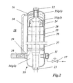
- the air cooler 10 has an elongate, vertical, substantially cylindrical pressure vessel 39, which is closed at the bottom and top by a curved bottom.
- a coaxial to the longitudinal axis of the air cooler 10 arrangement of a cylindrical central tube 24, the central tube 24 enclosing helical tube bundle 25 and the tube bundle 25 enclosing cylindrical inner shell 26 is housed.
- the central tube 24 opens at the upper end of the coaxial arrangement 24, 25, 26 in a subsequent to the tube bundle 25, outwardly closed by the inner shell 26 first space 33.
- the central tube 24 is at the lower end of the coaxial arrangement 24, 25, 26 by an adjoining the tube bundle 25 second space 34 through an air inlet port 23 from outside the pressure vessel 39 with air acted upon.
- the jacket surrounding the tube bundle 25 and the first space 33 is designed as an inner jacket 26 separate from the pressure vessel 39.
- the inner casing 26 is surrounded concentrically by the cylindrical outer casing 28 of the pressure vessel 39 to form an annular gap 27 between inner casing 26 and outer casing 28.
- a third space 35 is formed at the upper end of the pressure vessel 39, which communicates with the second space 34 via the annular gap 27.
- a water inlet chamber 31 is arranged on the pressure vessel 39 in the region of the lower second space 34, which communicates with the lower end of the tube bundle 25 via (in FIG Fig. 2 Only slightly shown) leads is connected and receives via a control valve 37 from the outside water.
- a vapor exit chamber 32 is disposed in the region of the upper third space 35, which is connected to the upper end of the tube bundle 25 via leads and can be removed from the tube bundle 25 via the steam.
- the second space 34 is accessible via an air outlet port 29 from the outside.
- the third space 35 is connected to this air outlet port 29 in the manner of a bypass via a separate connecting pipe 30, which is connected on the input side to an outgoing from the third space 35 outlet nozzle 36 and the output ends in a tubular air outlet port 29 coaxially arranged diffuser 38
- Der Annular gap 27 has, for example, a width of 20 mm.
- a pressure p3 which is smaller than the pressure p2 due to the pressure losses in the annular gap 27.
- the bypass air flows via the outlet nozzle 36, the connecting pipe 30 and the diffuser 38 into the air outlet connection piece 29 arranged at the bottom, and there it mixes with the main air stream.
- the acceleration pressure drop in Air outlet port 29 lowers the static pressure in the air outlet port 29 to a value less than p2.
- This driving pressure difference is used to overcome the friction and curvature pressure drop and to achieve the bypass air flow through the annular gap 27.
- the desired bypass air flow eg 10% of the total air flow
Claims (7)
- Refroidisseur à air (10) pour centrales électriques (40), comprenant une cuve sous pression (39) dans laquelle est placé un agencement coaxial (24, 25, 26) composé d'un tube central cylindrique (24), d'un faisceau de tubes (25) en forme d'hélice entourant le tube central (24) et d'une enveloppe cylindrique (26) entourant le faisceau de tubes (25), le tube central (24) débouchant à une extrémité de l'agencement coaxial (24, 25, 26) dans une première chambre (33) connectée au faisceau de tubes (25) et isolée vers l'extérieur par l'enveloppe (26), le tube central (24) pouvant en outre être alimenté en air provenant de l'extérieur de la cuve sous pression (39) au niveau de l'autre extrémité de l'agencement coaxial (24, 25, 26) par le biais d'une deuxième chambre (34) connectée au faisceau de tubes (25) par l'intermédiaire d'une tubulure d'entrée d'air (23) et des moyens de raccordement (31, 32) étant prévus pour le faisceau de tubes (25) à l'aide desquels de l'eau peut être stockée dans le faisceau de tubes à partir de l'autre extrémité de l'agencement coaxial (24, 25, 26) et de la vapeur peut être sortie hors du faisceau de tubes (25) au niveau d'une extrémité et la deuxième chambre (34) étant accessible de l'extérieur par le biais d'une tubulure de sortie d'air (29), caractérisé en ce que l'enveloppe entourant le faisceau de tubes (25) et la première chambre (33) prend la forme d'une enveloppe intérieure (26) séparée de la cuve sous pression (39), que l'enveloppe intérieure (26) est concentriquement entourée par une enveloppe extérieure (28) cylindrique de la cuve sous pression (39) par formation d'une fente annulaire (27) placée entre l'enveloppe intérieure (26) et l'enveloppe extérieure (28), qu'une troisième chambre (35) est réalisée à l'extérieur de la première chambre (33) et à l'intérieur de la cuve sous pression (39), ladite chambre étant reliée à la deuxième chambre (34) par le biais de la fente annulaire (27) et que la troisième chambre (35) est reliée à la tubulure de sortie d'air (29) par le biais de moyens de raccordement (30, 36, 38) séparés de telle sorte qu'une pression (p3) inférieure à la pression (p2) régnant dans la deuxième chambre s'exerce lorsque la troisième chambre (35) est en fonctionnement.
- Refroidisseur à air selon la revendication 1, caractérisé en ce que les moyens de raccordement séparés comprennent au moins une tubulure de sortie (36) débouchant de l'extérieur dans la troisième chambre (35) ainsi qu'un tube de raccordement (30) reliant l'au moins un tube de sortie (36) à la tubulure de sortie d' air (29).
- Refroidisseur à air selon la revendication 2, caractérisé en ce que le tube de raccordement prend fin dans un diffuseur (38) à l'intérieur de la tubulure de sortie d'air (29).
- Refroidisseur à air selon l'une quelconque des revendications 1 à 3, caractérisé en ce que la fente annulaire (27) et les moyens de raccordement (30, 36, 38) séparés sont dimensionnés de telle sorte que le flux d'air de dérivation traversant la fente annulaire (27) constitue environ 10 % du flux d'air total traversant le refroidisseur à air (10).
- Refroidisseur à air selon l'une quelconque des revendications 1 à 4, caractérisé en ce qu'un compartiment d'entrée d'eau (31) reliée au côté du faisceau de tube (25) orienté vers la deuxième chambre (34) est disposé dans la zone de la deuxième chambre (34) au niveau de la cuve sous pression (39) et qu'un compartiment de sortie de vapeur (32) relié au côté du faisceau de tubes (25) orienté vers la troisième chambre (35) est disposé dans la zone de la troisième chambre (35).
- Refroidisseur à air selon l'une quelconque des revendications 1 à 5, caractérisé en ce que le refroidisseur à air (10) est vertical et que la deuxième chambre (34) est disposée en dessous et que la première et la troisième chambres (33, 35) sont disposées au-dessus.
- Application de refroidisseur d'air (10) selon la revendication 1, servant au refroidissement de l'air de refroidissement (11) sortant d'un compresseur (1) dans une centrale électrique combinée (40), l'eau étant prélevée dans un système de production de vapeur de refroidissement (15) pour être stockée dans le faisceau de tubes (25) et la vapeur produite dans le faisceau de tubes (25) étant stockée dans le système de production de vapeur de refroidissement (15).
Applications Claiming Priority (3)
| Application Number | Priority Date | Filing Date | Title |
|---|---|---|---|
| DE10303341A DE10303341A1 (de) | 2003-01-29 | 2003-01-29 | Luftkühler für Kraftwerksanlagen sowie Anwendung eines solchen Luftkühlers |
| DE10303341 | 2003-01-29 | ||
| PCT/EP2004/050046 WO2004072544A1 (fr) | 2003-01-29 | 2004-01-28 | Refroidisseur a air pour centrales electriques et application d'un refroidisseur a air de ce type |
Publications (2)
| Publication Number | Publication Date |
|---|---|
| EP1590603A1 EP1590603A1 (fr) | 2005-11-02 |
| EP1590603B1 true EP1590603B1 (fr) | 2012-10-17 |
Family
ID=32747497
Family Applications (1)
| Application Number | Title | Priority Date | Filing Date |
|---|---|---|---|
| EP04705821A Expired - Lifetime EP1590603B1 (fr) | 2003-01-29 | 2004-01-28 | Refroidisseur a air pour centrales electriques et application d'un refroidisseur a air de ce type |
Country Status (8)
| Country | Link |
|---|---|
| US (1) | US7481265B2 (fr) |
| EP (1) | EP1590603B1 (fr) |
| JP (1) | JP4611969B2 (fr) |
| CN (1) | CN100386562C (fr) |
| DE (1) | DE10303341A1 (fr) |
| ES (1) | ES2397837T3 (fr) |
| PT (1) | PT1590603E (fr) |
| WO (1) | WO2004072544A1 (fr) |
Families Citing this family (11)
| Publication number | Priority date | Publication date | Assignee | Title |
|---|---|---|---|---|
| EP1808588A1 (fr) * | 2006-01-14 | 2007-07-18 | Thermal PowerTec GmbH | Augmentation de la puissance et du rendement dans des centrales à turbine à gaz et à cycle combiné |
| US8006651B2 (en) * | 2007-05-15 | 2011-08-30 | Combustion & Energy Systems Ltd. | Reverse-flow condensing economizer and heat recovery method |
| EP2067940B2 (fr) | 2007-09-07 | 2023-02-15 | General Electric Technology GmbH | Procédé de fonctionnement d'ne centrale à cycle combiné, et centrale à cycle combiné pour la mise en oeuvre dudit procédé |
| US8707709B2 (en) * | 2009-03-31 | 2014-04-29 | General Electric Company | Systems and methods for controlling compressor extraction cooling |
| DE102013017566A1 (de) * | 2013-10-22 | 2015-04-23 | Linde Aktiengesellschaft | Verwendung eines gewickelten Wärmeübertragers zur Erzeugung überhitzten Dampfs aus Verbrennungs- oder Abgasen bei Heizanlagen oder Verbrennungsmaschinen |
| US9291401B2 (en) | 2014-02-24 | 2016-03-22 | Combustion & Energy Systems Ltd. | Split flow condensing economizer and heat recovery method |
| CN107109979A (zh) * | 2014-11-19 | 2017-08-29 | 易维佳知识产权控股有限公司 | 抽吸装置 |
| US10774741B2 (en) * | 2016-01-26 | 2020-09-15 | General Electric Company | Hybrid propulsion system for a gas turbine engine including a fuel cell |
| US11168951B2 (en) | 2016-07-14 | 2021-11-09 | General Electric Company | Entrainment heat exchanger |
| EP3354878B1 (fr) * | 2017-01-31 | 2019-08-28 | Ansaldo Energia Switzerland AG | Échangeur de chaleur pour moteur à turbine à gaz |
| CN116817635B (zh) * | 2023-08-30 | 2023-11-10 | 山东豪迈机械制造有限公司 | 一种绕管式换热器 |
Family Cites Families (9)
| Publication number | Priority date | Publication date | Assignee | Title |
|---|---|---|---|---|
| US3741167A (en) * | 1971-03-02 | 1973-06-26 | Foster Wheeler Corp | Sodium heated steam generator |
| US4471836A (en) * | 1982-01-15 | 1984-09-18 | Arthur C. Knox, Jr. | Vent condenser |
| CH665019A5 (de) * | 1984-08-21 | 1988-04-15 | Sulzer Ag | Waermeuebertrager, insbesondere zum kuehlen von gas aus einem hochtemperaturreaktor. |
| DE3501805A1 (de) * | 1985-01-21 | 1986-07-24 | Anton Steinecker Maschinenfabrik Gmbh, 8050 Freising | Behaelter fuer die kochung von maische oder wuerze |
| DE3529634A1 (de) * | 1985-08-19 | 1987-02-26 | Steinmueller Gmbh L & C | Waermetauscher fuer den waermetausch zwischen einem heissen gas und einem in rohrbuendelheizflaechen gefuehrten stroemungsmittel, insbesondere dampferzeuger fuer gasgekuehlte hochtemperaturreaktoren |
| DE3604288A1 (de) * | 1986-02-12 | 1987-08-13 | Uhde Gmbh | Vorrichtung als waermetauscher, insbesondere zur kuehlung von prozessgas oder zur erhitzung von dampf |
| DE4142375A1 (de) * | 1991-12-20 | 1993-07-08 | Siemens Ag | Kuehlluftkuehler fuer gasturbinen |
| DE19541914A1 (de) * | 1995-11-10 | 1997-05-15 | Asea Brown Boveri | Kühlluftkühler für Kraftwerksanlagen |
| DE10041413B4 (de) * | 1999-08-25 | 2011-05-05 | Alstom (Switzerland) Ltd. | Verfahren zum Betrieb einer Kraftwerksanlage |
-
2003
- 2003-01-29 DE DE10303341A patent/DE10303341A1/de not_active Withdrawn
-
2004
- 2004-01-28 WO PCT/EP2004/050046 patent/WO2004072544A1/fr active Application Filing
- 2004-01-28 CN CNB2004800031201A patent/CN100386562C/zh not_active Expired - Fee Related
- 2004-01-28 ES ES04705821T patent/ES2397837T3/es not_active Expired - Lifetime
- 2004-01-28 JP JP2006501989A patent/JP4611969B2/ja not_active Expired - Fee Related
- 2004-01-28 EP EP04705821A patent/EP1590603B1/fr not_active Expired - Lifetime
- 2004-01-28 PT PT47058219T patent/PT1590603E/pt unknown
-
2005
- 2005-07-29 US US11/192,175 patent/US7481265B2/en not_active Expired - Fee Related
Also Published As
| Publication number | Publication date |
|---|---|
| WO2004072544A1 (fr) | 2004-08-26 |
| PT1590603E (pt) | 2013-01-25 |
| AU2004210904A1 (en) | 2004-08-26 |
| ES2397837T3 (es) | 2013-03-11 |
| EP1590603A1 (fr) | 2005-11-02 |
| US20060080964A1 (en) | 2006-04-20 |
| CN100386562C (zh) | 2008-05-07 |
| CN1745278A (zh) | 2006-03-08 |
| JP4611969B2 (ja) | 2011-01-12 |
| JP2006521527A (ja) | 2006-09-21 |
| DE10303341A1 (de) | 2004-08-26 |
| US7481265B2 (en) | 2009-01-27 |
Similar Documents
| Publication | Publication Date | Title |
|---|---|---|
| DE60133268T2 (de) | Thermokinetischer verdichter | |
| DE602004011762T2 (de) | Verfahren zum betrieb einer gasturbinengruppe | |
| EP0516995B1 (fr) | Centrale combinée à gaz et à vapeur | |
| EP0924410B1 (fr) | Procédé d'utilisation d'un groupe generateur à turbines à gaz | |
| EP1243757B1 (fr) | Procédé de fonctionnement d'une centrale d'énergie | |
| DE10041413B4 (de) | Verfahren zum Betrieb einer Kraftwerksanlage | |
| EP1483483B1 (fr) | Traitement d'energie thermique | |
| EP0773349B1 (fr) | Générateur de vapeur à hélice pour centrales | |
| DE19745272C2 (de) | Gas- und Dampfturbinenanlage und Verfahren zum Betreiben einer derartigen Anlage | |
| EP2368021B1 (fr) | Générateur de vapeur à récupération de chaleur et procédé pour améliorer le fonctionnement d'un générateur de vapeur à récupération de chaleur | |
| EP0425717A1 (fr) | Générateur de vapeur à passage unique | |
| EP1590603B1 (fr) | Refroidisseur a air pour centrales electriques et application d'un refroidisseur a air de ce type | |
| DE19501471A1 (de) | Turbine, insbesondere Gasturbine | |
| DE10330859A1 (de) | Verfahren zum Betrieb von emissionsfreien Gasturbinenkraftwerken | |
| EP1390606B2 (fr) | Dispositif de refroidissement du fluide de refroidissement d'une turbine a gaz et ensemble turbine a gaz et turbine a vapeur comportant un tel dispositif | |
| EP0666412B1 (fr) | Méthode pour refroidir l'air de refroidissement pour une turbine à gaz | |
| DE2900014A1 (de) | Gasturbinenvorrichtung | |
| EP0709561B1 (fr) | Centrale électrique | |
| DE102014206474A1 (de) | Anlage zum Bereitstellen von Wärmeenergie für Wärmeverbraucher | |
| DE10358233A1 (de) | Luftspeicherkraftanlage | |
| DE695838C (de) | Mit einem gasfoermigen Arbeitsmittel betriebene Kraftmaschinenanlage | |
| EP1808588A1 (fr) | Augmentation de la puissance et du rendement dans des centrales à turbine à gaz et à cycle combiné | |
| EP1275820B1 (fr) | Turbine à gaz et sa méthode d'opération | |
| EP0158629A2 (fr) | Cycle à vapeur pour installation énergétique à vapeur | |
| EP1576331B1 (fr) | Condenseur avec systeme de deaeration/degazage pour centrale thermique |
Legal Events
| Date | Code | Title | Description |
|---|---|---|---|
| PUAI | Public reference made under article 153(3) epc to a published international application that has entered the european phase |
Free format text: ORIGINAL CODE: 0009012 |
|
| 17P | Request for examination filed |
Effective date: 20050728 |
|
| AK | Designated contracting states |
Kind code of ref document: A1 Designated state(s): AT BE BG CH CY CZ DE DK EE ES FI FR GB GR HU IE IT LI LU MC NL PT RO SE SI SK TR |
|
| AX | Request for extension of the european patent |
Extension state: AL LT LV MK |
|
| DAX | Request for extension of the european patent (deleted) | ||
| GRAP | Despatch of communication of intention to grant a patent |
Free format text: ORIGINAL CODE: EPIDOSNIGR1 |
|
| GRAS | Grant fee paid |
Free format text: ORIGINAL CODE: EPIDOSNIGR3 |
|
| GRAA | (expected) grant |
Free format text: ORIGINAL CODE: 0009210 |
|
| AK | Designated contracting states |
Kind code of ref document: B1 Designated state(s): AT BE BG CH CY CZ DE DK EE ES FI FR GB GR HU IE IT LI LU MC NL PT RO SE SI SK TR |
|
| REG | Reference to a national code |
Ref country code: GB Ref legal event code: FG4D Free format text: NOT ENGLISH Ref country code: DE Ref legal event code: R081 Ref document number: 502004013821 Country of ref document: DE Owner name: GENERAL ELECTRIC TECHNOLOGY GMBH, CH Free format text: FORMER OWNER: ALSTOM TECHNOLOGY LTD., BADEN, CH Ref country code: DE Ref legal event code: R081 Ref document number: 502004013821 Country of ref document: DE Owner name: ANSALDO ENERGIA IP UK LIMITED, GB Free format text: FORMER OWNER: ALSTOM TECHNOLOGY LTD., BADEN, CH |
|
| REG | Reference to a national code |
Ref country code: CH Ref legal event code: EP |
|
| REG | Reference to a national code |
Ref country code: IE Ref legal event code: FG4D Free format text: LANGUAGE OF EP DOCUMENT: GERMAN |
|
| REG | Reference to a national code |
Ref country code: AT Ref legal event code: REF Ref document number: 580090 Country of ref document: AT Kind code of ref document: T Effective date: 20121115 |
|
| REG | Reference to a national code |
Ref country code: DE Ref legal event code: R096 Ref document number: 502004013821 Country of ref document: DE Effective date: 20121213 |
|
| REG | Reference to a national code |
Ref country code: PT Ref legal event code: SC4A Free format text: AVAILABILITY OF NATIONAL TRANSLATION Effective date: 20130115 |
|
| REG | Reference to a national code |
Ref country code: NL Ref legal event code: T3 |
|
| REG | Reference to a national code |
Ref country code: ES Ref legal event code: FG2A Ref document number: 2397837 Country of ref document: ES Kind code of ref document: T3 Effective date: 20130311 |
|
| REG | Reference to a national code |
Ref country code: GR Ref legal event code: EP Ref document number: 20130400078 Country of ref document: GR Effective date: 20130225 |
|
| PG25 | Lapsed in a contracting state [announced via postgrant information from national office to epo] |
Ref country code: FI Free format text: LAPSE BECAUSE OF FAILURE TO SUBMIT A TRANSLATION OF THE DESCRIPTION OR TO PAY THE FEE WITHIN THE PRESCRIBED TIME-LIMIT Effective date: 20121017 Ref country code: SE Free format text: LAPSE BECAUSE OF FAILURE TO SUBMIT A TRANSLATION OF THE DESCRIPTION OR TO PAY THE FEE WITHIN THE PRESCRIBED TIME-LIMIT Effective date: 20121017 |
|
| PG25 | Lapsed in a contracting state [announced via postgrant information from national office to epo] |
Ref country code: CY Free format text: LAPSE BECAUSE OF FAILURE TO SUBMIT A TRANSLATION OF THE DESCRIPTION OR TO PAY THE FEE WITHIN THE PRESCRIBED TIME-LIMIT Effective date: 20121017 Ref country code: SI Free format text: LAPSE BECAUSE OF FAILURE TO SUBMIT A TRANSLATION OF THE DESCRIPTION OR TO PAY THE FEE WITHIN THE PRESCRIBED TIME-LIMIT Effective date: 20121017 |
|
| BERE | Be: lapsed |
Owner name: ALSTOM TECHNOLOGY LTD Effective date: 20130131 |
|
| PG25 | Lapsed in a contracting state [announced via postgrant information from national office to epo] |
Ref country code: CZ Free format text: LAPSE BECAUSE OF FAILURE TO SUBMIT A TRANSLATION OF THE DESCRIPTION OR TO PAY THE FEE WITHIN THE PRESCRIBED TIME-LIMIT Effective date: 20121017 Ref country code: DK Free format text: LAPSE BECAUSE OF FAILURE TO SUBMIT A TRANSLATION OF THE DESCRIPTION OR TO PAY THE FEE WITHIN THE PRESCRIBED TIME-LIMIT Effective date: 20121017 Ref country code: EE Free format text: LAPSE BECAUSE OF FAILURE TO SUBMIT A TRANSLATION OF THE DESCRIPTION OR TO PAY THE FEE WITHIN THE PRESCRIBED TIME-LIMIT Effective date: 20121017 Ref country code: SK Free format text: LAPSE BECAUSE OF FAILURE TO SUBMIT A TRANSLATION OF THE DESCRIPTION OR TO PAY THE FEE WITHIN THE PRESCRIBED TIME-LIMIT Effective date: 20121017 Ref country code: BG Free format text: LAPSE BECAUSE OF FAILURE TO SUBMIT A TRANSLATION OF THE DESCRIPTION OR TO PAY THE FEE WITHIN THE PRESCRIBED TIME-LIMIT Effective date: 20130117 |
|
| PLBE | No opposition filed within time limit |
Free format text: ORIGINAL CODE: 0009261 |
|
| STAA | Information on the status of an ep patent application or granted ep patent |
Free format text: STATUS: NO OPPOSITION FILED WITHIN TIME LIMIT |
|
| PG25 | Lapsed in a contracting state [announced via postgrant information from national office to epo] |
Ref country code: MC Free format text: LAPSE BECAUSE OF NON-PAYMENT OF DUE FEES Effective date: 20130131 Ref country code: RO Free format text: LAPSE BECAUSE OF FAILURE TO SUBMIT A TRANSLATION OF THE DESCRIPTION OR TO PAY THE FEE WITHIN THE PRESCRIBED TIME-LIMIT Effective date: 20121017 |
|
| REG | Reference to a national code |
Ref country code: CH Ref legal event code: PL |
|
| 26N | No opposition filed |
Effective date: 20130718 |
|
| PG25 | Lapsed in a contracting state [announced via postgrant information from national office to epo] |
Ref country code: CH Free format text: LAPSE BECAUSE OF NON-PAYMENT OF DUE FEES Effective date: 20130131 Ref country code: BE Free format text: LAPSE BECAUSE OF NON-PAYMENT OF DUE FEES Effective date: 20130131 Ref country code: LI Free format text: LAPSE BECAUSE OF NON-PAYMENT OF DUE FEES Effective date: 20130131 |
|
| REG | Reference to a national code |
Ref country code: DE Ref legal event code: R097 Ref document number: 502004013821 Country of ref document: DE Effective date: 20130718 |
|
| REG | Reference to a national code |
Ref country code: AT Ref legal event code: MM01 Ref document number: 580090 Country of ref document: AT Kind code of ref document: T Effective date: 20130128 |
|
| PG25 | Lapsed in a contracting state [announced via postgrant information from national office to epo] |
Ref country code: AT Free format text: LAPSE BECAUSE OF NON-PAYMENT OF DUE FEES Effective date: 20130128 |
|
| PG25 | Lapsed in a contracting state [announced via postgrant information from national office to epo] |
Ref country code: LU Free format text: LAPSE BECAUSE OF NON-PAYMENT OF DUE FEES Effective date: 20130128 Ref country code: HU Free format text: LAPSE BECAUSE OF FAILURE TO SUBMIT A TRANSLATION OF THE DESCRIPTION OR TO PAY THE FEE WITHIN THE PRESCRIBED TIME-LIMIT; INVALID AB INITIO Effective date: 20040128 |
|
| REG | Reference to a national code |
Ref country code: FR Ref legal event code: PLFP Year of fee payment: 13 |
|
| REG | Reference to a national code |
Ref country code: NL Ref legal event code: HC Owner name: GENERAL ELECTRIC TECHNOLOGY GMBH; CH Free format text: DETAILS ASSIGNMENT: VERANDERING VAN EIGENAAR(S), VERANDERING VAN NAAM VAN DE EIGENAAR(S); FORMER OWNER NAME: ALSTOM TECHNOLOGY LTD Effective date: 20160623 |
|
| REG | Reference to a national code |
Ref country code: DE Ref legal event code: R082 Ref document number: 502004013821 Country of ref document: DE Representative=s name: RUEGER | ABEL PATENT- UND RECHTSANWAELTE, DE Ref country code: DE Ref legal event code: R082 Ref document number: 502004013821 Country of ref document: DE Representative=s name: RUEGER ABEL PATENTANWAELTE PARTGMBB, DE Ref country code: DE Ref legal event code: R082 Ref document number: 502004013821 Country of ref document: DE Representative=s name: RUEGER, BARTHELT & ABEL, DE Ref country code: DE Ref legal event code: R081 Ref document number: 502004013821 Country of ref document: DE Owner name: GENERAL ELECTRIC TECHNOLOGY GMBH, CH Free format text: FORMER OWNER: ALSTOM TECHNOLOGY LTD., BADEN, CH Ref country code: DE Ref legal event code: R081 Ref document number: 502004013821 Country of ref document: DE Owner name: ANSALDO ENERGIA IP UK LIMITED, GB Free format text: FORMER OWNER: ALSTOM TECHNOLOGY LTD., BADEN, CH Ref country code: DE Ref legal event code: R082 Ref document number: 502004013821 Country of ref document: DE Representative=s name: RUEGER ABEL PATENT- UND RECHTSANWAELTE, DE |
|
| REG | Reference to a national code |
Ref country code: ES Ref legal event code: PC2A Owner name: GENERAL ELECTRIC TECHNOLOGY GMBH Effective date: 20161115 |
|
| REG | Reference to a national code |
Ref country code: FR Ref legal event code: CD Owner name: ALSTOM TECHNOLOGY LTD, CH Effective date: 20161124 |
|
| REG | Reference to a national code |
Ref country code: FR Ref legal event code: PLFP Year of fee payment: 14 |
|
| REG | Reference to a national code |
Ref country code: NL Ref legal event code: PD Owner name: ANSALDO ENERGIA IP UK LIMITED; GB Free format text: DETAILS ASSIGNMENT: CHANGE OF OWNER(S), ASSIGNMENT; FORMER OWNER NAME: GENERAL ELECTRIC TECHNOLOGY GMBH Effective date: 20170301 |
|
| PGFP | Annual fee paid to national office [announced via postgrant information from national office to epo] |
Ref country code: NL Payment date: 20170130 Year of fee payment: 14 |
|
| PGFP | Annual fee paid to national office [announced via postgrant information from national office to epo] |
Ref country code: GR Payment date: 20170127 Year of fee payment: 14 |
|
| PGFP | Annual fee paid to national office [announced via postgrant information from national office to epo] |
Ref country code: PT Payment date: 20170127 Year of fee payment: 14 Ref country code: GB Payment date: 20170131 Year of fee payment: 14 Ref country code: IE Payment date: 20170127 Year of fee payment: 14 |
|
| PGFP | Annual fee paid to national office [announced via postgrant information from national office to epo] |
Ref country code: TR Payment date: 20170127 Year of fee payment: 14 |
|
| REG | Reference to a national code |
Ref country code: DE Ref legal event code: R082 Ref document number: 502004013821 Country of ref document: DE Representative=s name: RUEGER | ABEL PATENT- UND RECHTSANWAELTE, DE Ref country code: DE Ref legal event code: R082 Ref document number: 502004013821 Country of ref document: DE Representative=s name: RUEGER ABEL PATENTANWAELTE PARTGMBB, DE Ref country code: DE Ref legal event code: R082 Ref document number: 502004013821 Country of ref document: DE Representative=s name: RUEGER, BARTHELT & ABEL, DE Ref country code: DE Ref legal event code: R081 Ref document number: 502004013821 Country of ref document: DE Owner name: ANSALDO ENERGIA IP UK LIMITED, GB Free format text: FORMER OWNER: GENERAL ELECTRIC TECHNOLOGY GMBH, BADEN, CH Ref country code: DE Ref legal event code: R082 Ref document number: 502004013821 Country of ref document: DE Representative=s name: RUEGER ABEL PATENT- UND RECHTSANWAELTE, DE |
|
| REG | Reference to a national code |
Ref country code: GB Ref legal event code: 732E Free format text: REGISTERED BETWEEN 20170824 AND 20170830 |
|
| REG | Reference to a national code |
Ref country code: ES Ref legal event code: PC2A Owner name: ANSALDO ENERGIA IP UK LIMITED Effective date: 20170927 |
|
| REG | Reference to a national code |
Ref country code: FR Ref legal event code: PLFP Year of fee payment: 15 |
|
| REG | Reference to a national code |
Ref country code: FR Ref legal event code: TP Owner name: ANSALDO ENERGIA IP UK LIMITED, GB Effective date: 20171221 |
|
| PGFP | Annual fee paid to national office [announced via postgrant information from national office to epo] |
Ref country code: ES Payment date: 20180227 Year of fee payment: 15 |
|
| PGFP | Annual fee paid to national office [announced via postgrant information from national office to epo] |
Ref country code: FR Payment date: 20180119 Year of fee payment: 15 |
|
| REG | Reference to a national code |
Ref country code: NL Ref legal event code: MM Effective date: 20180201 |
|
| GBPC | Gb: european patent ceased through non-payment of renewal fee |
Effective date: 20180128 |
|
| PG25 | Lapsed in a contracting state [announced via postgrant information from national office to epo] |
Ref country code: PT Free format text: LAPSE BECAUSE OF NON-PAYMENT OF DUE FEES Effective date: 20180730 |
|
| REG | Reference to a national code |
Ref country code: IE Ref legal event code: MM4A |
|
| PG25 | Lapsed in a contracting state [announced via postgrant information from national office to epo] |
Ref country code: GB Free format text: LAPSE BECAUSE OF NON-PAYMENT OF DUE FEES Effective date: 20180128 Ref country code: NL Free format text: LAPSE BECAUSE OF NON-PAYMENT OF DUE FEES Effective date: 20180201 Ref country code: GR Free format text: LAPSE BECAUSE OF NON-PAYMENT OF DUE FEES Effective date: 20180802 |
|
| PG25 | Lapsed in a contracting state [announced via postgrant information from national office to epo] |
Ref country code: IE Free format text: LAPSE BECAUSE OF NON-PAYMENT OF DUE FEES Effective date: 20180128 |
|
| PG25 | Lapsed in a contracting state [announced via postgrant information from national office to epo] |
Ref country code: FR Free format text: LAPSE BECAUSE OF NON-PAYMENT OF DUE FEES Effective date: 20190131 |
|
| REG | Reference to a national code |
Ref country code: ES Ref legal event code: FD2A Effective date: 20200310 |
|
| PG25 | Lapsed in a contracting state [announced via postgrant information from national office to epo] |
Ref country code: ES Free format text: LAPSE BECAUSE OF NON-PAYMENT OF DUE FEES Effective date: 20190129 |
|
| PGFP | Annual fee paid to national office [announced via postgrant information from national office to epo] |
Ref country code: DE Payment date: 20220119 Year of fee payment: 19 |
|
| PGFP | Annual fee paid to national office [announced via postgrant information from national office to epo] |
Ref country code: IT Payment date: 20220120 Year of fee payment: 19 |
|
| PG25 | Lapsed in a contracting state [announced via postgrant information from national office to epo] |
Ref country code: TR Free format text: LAPSE BECAUSE OF NON-PAYMENT OF DUE FEES Effective date: 20180128 |
|
| REG | Reference to a national code |
Ref country code: DE Ref legal event code: R119 Ref document number: 502004013821 Country of ref document: DE |
|
| PG25 | Lapsed in a contracting state [announced via postgrant information from national office to epo] |
Ref country code: DE Free format text: LAPSE BECAUSE OF NON-PAYMENT OF DUE FEES Effective date: 20230801 |
|
| PG25 | Lapsed in a contracting state [announced via postgrant information from national office to epo] |
Ref country code: IT Free format text: LAPSE BECAUSE OF NON-PAYMENT OF DUE FEES Effective date: 20230128 |