EP1590274B1 - Förderband - Google Patents
Förderband Download PDFInfo
- Publication number
- EP1590274B1 EP1590274B1 EP03779760A EP03779760A EP1590274B1 EP 1590274 B1 EP1590274 B1 EP 1590274B1 EP 03779760 A EP03779760 A EP 03779760A EP 03779760 A EP03779760 A EP 03779760A EP 1590274 B1 EP1590274 B1 EP 1590274B1
- Authority
- EP
- European Patent Office
- Prior art keywords
- conveyor
- cross members
- structures
- slide rails
- disposed
- Prior art date
- Legal status (The legal status is an assumption and is not a legal conclusion. Google has not performed a legal analysis and makes no representation as to the accuracy of the status listed.)
- Expired - Lifetime
Links
- 238000003780 insertion Methods 0.000 claims description 2
- 230000037431 insertion Effects 0.000 claims description 2
- 238000004140 cleaning Methods 0.000 abstract description 6
- 238000006073 displacement reaction Methods 0.000 description 3
- 238000011059 hazard and critical control points analysis Methods 0.000 description 3
- 238000010276 construction Methods 0.000 description 2
- 239000002994 raw material Substances 0.000 description 2
- 238000003466 welding Methods 0.000 description 2
- 241000894006 Bacteria Species 0.000 description 1
- 239000004743 Polypropylene Substances 0.000 description 1
- 238000005520 cutting process Methods 0.000 description 1
- 230000001066 destructive effect Effects 0.000 description 1
- 230000000694 effects Effects 0.000 description 1
- 238000004519 manufacturing process Methods 0.000 description 1
- 239000000463 material Substances 0.000 description 1
- 239000004033 plastic Substances 0.000 description 1
- -1 polypropylene Polymers 0.000 description 1
- 229920001155 polypropylene Polymers 0.000 description 1
Images


Classifications
-
- B—PERFORMING OPERATIONS; TRANSPORTING
- B65—CONVEYING; PACKING; STORING; HANDLING THIN OR FILAMENTARY MATERIAL
- B65G—TRANSPORT OR STORAGE DEVICES, e.g. CONVEYORS FOR LOADING OR TIPPING, SHOP CONVEYOR SYSTEMS OR PNEUMATIC TUBE CONVEYORS
- B65G21/00—Supporting or protective framework or housings for endless load-carriers or traction elements of belt or chain conveyors
- B65G21/20—Means incorporated in, or attached to, framework or housings for guiding load-carriers, traction elements or loads supported on moving surfaces
- B65G21/2045—Mechanical means for guiding or retaining the load on the load-carrying surface
- B65G21/2063—Mechanical means for guiding or retaining the load on the load-carrying surface comprising elements not movable in the direction of load-transport
- B65G21/2072—Laterial guidance means
-
- B—PERFORMING OPERATIONS; TRANSPORTING
- B65—CONVEYING; PACKING; STORING; HANDLING THIN OR FILAMENTARY MATERIAL
- B65G—TRANSPORT OR STORAGE DEVICES, e.g. CONVEYORS FOR LOADING OR TIPPING, SHOP CONVEYOR SYSTEMS OR PNEUMATIC TUBE CONVEYORS
- B65G21/00—Supporting or protective framework or housings for endless load-carriers or traction elements of belt or chain conveyors
- B65G21/02—Supporting or protective framework or housings for endless load-carriers or traction elements of belt or chain conveyors consisting essentially of struts, ties, or like structural elements
- B65G21/06—Supporting or protective framework or housings for endless load-carriers or traction elements of belt or chain conveyors consisting essentially of struts, ties, or like structural elements constructed to facilitate rapid assembly or dismantling
-
- B—PERFORMING OPERATIONS; TRANSPORTING
- B65—CONVEYING; PACKING; STORING; HANDLING THIN OR FILAMENTARY MATERIAL
- B65G—TRANSPORT OR STORAGE DEVICES, e.g. CONVEYORS FOR LOADING OR TIPPING, SHOP CONVEYOR SYSTEMS OR PNEUMATIC TUBE CONVEYORS
- B65G21/00—Supporting or protective framework or housings for endless load-carriers or traction elements of belt or chain conveyors
- B65G21/20—Means incorporated in, or attached to, framework or housings for guiding load-carriers, traction elements or loads supported on moving surfaces
- B65G21/22—Rails or the like engaging sliding elements or rollers attached to load-carriers or traction elements
-
- B—PERFORMING OPERATIONS; TRANSPORTING
- B65—CONVEYING; PACKING; STORING; HANDLING THIN OR FILAMENTARY MATERIAL
- B65G—TRANSPORT OR STORAGE DEVICES, e.g. CONVEYORS FOR LOADING OR TIPPING, SHOP CONVEYOR SYSTEMS OR PNEUMATIC TUBE CONVEYORS
- B65G2207/00—Indexing codes relating to constructional details, configuration and additional features of a handling device, e.g. Conveyors
- B65G2207/26—Hygienic features, e.g. easy to sanitize
Definitions
- the present invention concerns a conveyor of the kind which includes longitudinal conveyor structures, a motorised drive pulley with toothed external wheels arranged for driving a slat conveyor which is guided by and carried at the sides of slide rails in parallel with the conveyor structures, and means for returning the slat conveyor between the front end of the conveyor and a pulley at the rear end of the conveyor.
- Such conveyors are well-known and are used for many purposes, particularly within the food industry, for transporting materials and semi-manufactured products as well as finished products which are either placed directly on the carrier surface of the conveyor or which are placed in plastic boxes or the like during transport.
- the requirements for such a conveyor are particularly high within the food industry, where high capacity combined with minimal service, small manufacturing cost, rapid and secure putting into operation, good hygiene conditions and quiet transport are some of the key words. Furthermore, there are requirements to service and cleaning friendliness so that in the shortest possible time it is possible to perform replacement of relevant parts, such as wear part etc. on the conveyor. Besides, there are requirements to hygiene, i.e. the conveyor is designed and adapted in such a way the access to its parts in connection with cleaning is facilitated as much as possible, and furthermore that the conveyor does not include parts that collect dirt.
- Such a conveyor is also known from FR-A1-2 783 814, where the frame is built up of two longitudinal conveyor structures that are mutually connected by a number of cross members with circular/rectangular and flat cross-sections.
- the slide rails of the conveyor are supported by cross members with rectangular cross-section, where the slide rails are disposed in cutouts made for the purpose.
- the slide rails are furthermore secured in their position by through-going cross members with circular cross-section which are let in through holes in the structures and welded to the latter.
- the cross members with rectangular cross-sections furthermore includes slotted apertures in the lower half through which the conveyor belt is returned, supported by a number of slide members with upward facing, convex shape.
- the frame for the said conveyor can be made of e.g. polypropylene.
- the conveyor disclosed in FR-A1-2 873 814 seems to be very suitable for application in the food industry, but some problems are unsolved when considering its structural design.
- a conveyor of the kind indicated in the introduction which is peculiar in that the longitudinal conveyor structures are mutually connected with uniform, parallel, interspaced, laminar cross members that are largely evenly distributed along the entire course of the conveyor structures, the cross members including symmetrically disposed cutouts with laterally reversed profiles at a bearing side of the conveyor for receiving profiled slide rails engaging the cutouts by inserting the slide rails from the rear end of the conveyor and against a stop disposed at or near the cross member which is disposed closest to the motorised drive pulley.
- a conveyor with wear parts namely the slide rails upon which the slat conveyor is sliding, driven by the motorised drive pulley, while supporting the load placed upon the carrier surface of the conveyor, become very easy to replace without using cutting and welding tools.
- a replacement can be performed simply by exerting a rearwards pull in the profiled slide rails, which are hereby pulled out of the profiled cutouts in the laminar cross members.
- the use of laminar profiled cross member results in the area of the contact surfaces between the slide rails of the conveyor and the laminar cross members is reduced considerably in relation to the prior art conveyors, whereby greater cleaning friendliness and corresponding improvement of the hygiene is achieved.
- the slide rails of the conveyor are furthermore held fixed in their position in abutment with the stops disposed at or near the cross member closest to the motorised drive pulley sot that the slide rails are not carried with the slat conveyor and become wedged between this and the pulley.
- the slide rails are secured in the cutouts from moving caused by upwards directed forces, which e.g. can arise at heavy loads at the ends of the conveyor belt.
- the slat conveyor typically includes guide means for the returning section of the slat conveyor between front and rear ends of the conveyor.
- These guide means are typically constituted by idlers provided with a certain spacing along the length of the conveyor between front end and rear end. The said idlers are, however, relatively costly and time consuming to mount and service, why it is desirable to substitute the idlers with alternative guide means.
- the supporting guide means advantageously can be constituted by brackets that each include an upwards facing, convex carrier surface which is unilaterally bordered by a vertical guide surface, where the guide surfaces are facing and are disposed laterally reversed in relation to a vertical plane of symmetry of the conveyor.
- the said guide means for the returning part of the slat conveyor are thus making the hitherto used idlers superfluous, and the guide means will be readily mounted in symmetrical, interspaced cutouts for the lower section of the conveyor.
- the conveyor structures can be constituted by two open, interspaced, parallel sections that each have a largely flat web including at least one plane section, where each section is provided with a pair of diverging, lateral flanges, and where the pairs of flanges are oriented towards each other.
- HACCP the guidelines for the food industry termed HACCP
- the flanges of the sections have an inclination angle relative to the horizontal between 30° and 160°.
- the outwards sloping flanges on the sections that constitute the conveyor structures are meeting the requirement that they are to have a slope greater than 30° relative to a horizontal plane.
- a slope greater than or equal to 30° provides for the flange being drainable.
- the said design of the conveyor furthermore implies that the laminar cross members are becoming a substantial part of the structure of the conveyor, including a substantial part of its carrying capacity.
- the laminar cross members are fastened to the profiled conveyor structures by means of cup head bolts.
- the rounded heads of the cup head bolts further are providing that dirt is not collected in connection with these joints.
- the said conveyors also include cables for power supply to the drive motor and possibly existing control and signal cables.
- the conveyor may be adapted so that the cross members include further profiled cutouts for insertion of carrier means for cables from the front or rear ends of the conveyor.
- the cables are carried in a safe way, and furthermore it will be possible to use closed cable trays for carrying the said cables, whereby dirtying thereof from raw materials or commonly occurring dirt is avoided.
- the conveyor may furthermore include guide rails disposed in parallel with the sides of the slat conveyor, the guide rails being securing in support holders that are secured to the inclining flanges on the sections constituting the conveyor structures.
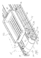
- Fig. 1 shows a slat conveyor 2 according to the invention in perspective viewed from above.
- the slat conveyor includes longitudinal, parallel conveyor structures 4, a motorised drive pulley 6 disposed at the front end 20 of the conveyor for driving a slat conveyor 10 and pulleys 7 disposed the rear end 22 of the conveyor.
- a load 42 On the carrier surface 18 of the conveyor provided by the slat conveyor 10 there is provided a load 42 in the form of a box.
- Fig. 2 which shows details of the front end 20 of the conveyor according to the invention, shows that the structures 4 are made up of edgewise positioned sections 32 with flanges 38 in pairs oriented towards the vertical plane 25 of symmetry of the conveyor, the flanges 38 in each pair sloping away from each other and extending away from the web 34 of the sections 32.
- the structures 4 are mutually connected by laminar cross members 14 that include profiled cutouts 16, cf. Figs. 4 and 5, in which are inserted slide rails 12 running in parallel and having a cross-sectional profile corresponding to and shaped for engaging the profiled cutouts 16 in the cross members 14.
- the parallel slide rails 12 are constituting support for the slat conveyor 10 and thereby for the carrier surface 18 of the conveyor.
- the cross member 14' closest to the motorised drive pulley includes an end stop 40 against which the ends of the slide rails 12 are abutting.
- the diverging, sloping flanges 38 on the edgewise placed sections 32 have an inclination which in the preferred embodiment is greater than or equal to 30° relative to a horizontal plane.
- the laminar cross members 14 include angular bends 44 provided with through-going holes 46 opposite corresponding holes 48 in the bottom or web 34 of the edgewise place sections 32.
- cup head bolts 50 As fastening means between the cross members 14 and the web 34 of the sections 32 are used cup head bolts 50, with the heads oriented towards the outer sides of the conveyor.
- a centre section of the web 34 in the edgewise placed sections 32 is displaced in parallel in relation to the remaining part of the web profile.
- holes for the bolts 50 are protected against dirt by the cup heads, an effect which enhanced by the heads being recessed by the displacement of the centre of the web 34 in relation to other sections of the web 34 facing outwards.
- the conveyor 2 includes guide rods 54 that are running in parallel with the sides 52 of the slat conveyor, the guide rods 54 being secured in support holders 56 that in turn are fastened to the upper flanges 38 of the sections 32 by means of cup head bolts 50.
- the rounded heads of the bolts 50 are here disposed at the outer side of the flange 4, also with the purpose of protecting the holes and bolts against dirtying.
- Fig. 3 which is a perspective view from above of the embodiment of the conveyor 2 according to the invention, the pulley 7 is suspended by an axle 58 in bearings.
- Fig. 4 is a perspective view of the conveyor 2 in Fig. 1, being viewed obliquely from below and shows clearly the profiled cutouts 16 in the laminar cross members 14 that connect the conveyor structures 4.
- the parallel extending slide rails 12 have a cross-section corresponding with the profiled cutouts 16, and the slide rails are inserted in the cutouts from one end of the conveyor.
- the laminar cross members and cutouts 23 include supporting guide means 24 for the returning, lower section of the slot conveyor 10.
- the supporting guide means 24 are constituted by brackets 24 that each includes an upwards facing, convex carrier surface 30 bordered at one side by a vertical guide member having a guide surface 28.
- Brackets 24 located at opposite sides of the conveyor are facing each other and are disposed laterally reversed in relation to the vertical plane 25 of symmetry of the conveyor.
- the brackets 24 may thus carry and guide the lower, returning section of the slot conveyor 10 from the motorised drive pulley 6 to the pulley at the rear end 22 of the conveyor.
- Fig. 5 shows in a corresponding way the design of the rear end of the conveyor as seen from below.
- the profiled slide rails 12 are seen to engage the undercut cutouts 16 in the laminar cross members 14, whereby the slide rails are secured against upwards displacement towards the carrier surface 18 of the conveyor.
- a conveyor which is very serviceable and which has wear parts, particularly the parallel slide rails 12, that may readily replaced by simply removing the slat conveyor from the slide rails 12 and dismounting the pulley, then pulling the slide rails rearwards while sliding in the profiled cutouts 16 in the laminar cross members 14.
- the conveyor 2 according to the invention is furthermore advantageous by the outwards sloping flanges 38 which have sufficient inclination for being drainable, thereby meeting the requirements of the standard HACCP.
Landscapes
- Mechanical Engineering (AREA)
- Engineering & Computer Science (AREA)
- Chain Conveyers (AREA)
- Liquid Crystal (AREA)
- Structure Of Belt Conveyors (AREA)
- Glass Compositions (AREA)
- Housing For Livestock And Birds (AREA)
- Insulated Conductors (AREA)
- Surface Acoustic Wave Elements And Circuit Networks Thereof (AREA)
- Amplifiers (AREA)
- Belt Conveyors (AREA)
- Formation And Processing Of Food Products (AREA)
- Screw Conveyors (AREA)
Claims (6)
- Förderband mit längsverlaufenden Förderbandaufbauten (4); einer motorbetriebenen Antriebsriemenscheibe (6) mit Außenzahnrädern (8), die zum Antreiben eines Scharnierbandförderers (10) angeordnet sind, der an den Seiten von Gleitschienen parallel mit den Förderbandaufbauten (4) geführt und gehaltert ist; und Einrichtungen (24), um den Scharnierbandförderer (10) zwischen dem vorderen Ende (3) des Förderbands und einer Riemenscheibe (7) am hinteren Ende (5) des Förderbands umkehren zu lassen,
dadurch gekennzeichnet, dass
die längsverlaufenden Förderbandaufbauten (4) gegenseitig mit gleichförmigen, parallelen, voneinander beabstandeten, lamellenförmigen Querteilen (14) verbunden sind, die im Wesentlichen gleichmäßig entlang des gesamten Verlaufs der Förderbandaufbauten (4) verteilt sind, wobei die Querteile symmetrisch angeordnete Ausschnitte (16) mit seitenverkehrten Profilen an einer Lagerseite (18) des Förderbands umfassen, um in die Ausschnitte (16) eingreifende Profilgleitschienen (12) aufzunehmen, indem die Gleitschienen (12) vom hinteren Ende (22) des Förderbands her und bis zu einem Anschlag (40) eingesteckt sind, der am oder nahe an dem Querteil (14') angeordnet ist, das sich der motorbetriebenen Antriebsriemenscheibe (6) am nächsten befindet. - Förderband nach Anspruch 1, dadurch gekennzeichnet, dass die Profilausschnitte (16) in den Querteilen (14) unterschnitten sind.
- Förderband nach Anspruch 1 oder 2, dadurch gekennzeichnet, dass die Querteile (14) darüber hinaus symmetrisch gesetzte, voneinander beabstandete Befestigungen (23) für Stützführungseinrichtungen (24) für den Scharnierbandförderer (10) an der Unterseite (26) des Förderbands umfassen, wobei die Stützführungseinrichtungen durch Bügel (24) gebildet sind, die jeweils eine nach oben gewandte, konvexe Auflagefläche (30) umfassen, die einseitig durch eine vertikale Führungsfläche (28) eingegrenzt ist, wobei die Führungsflächen (28) einander in Bezug auf eine vertikale Symmetrieebene (25) des Förderbands zugewandt und seitenverkehrt angeordnet sind.
- Förderband nach einem der Ansprüche 1 bis 3, dadurch gekennzeichnet, dass die Förderbandaufbauten (4) durch zwei offene, voneinander beabstandete, parallele Abschnitte (32) gebildet sind, die jeweils eine im Wesentlichen flache Bahn (34) mit mindestens einem planen Abschnitt (36) umfassen, an dem jeder Abschnitt (32) mit einem Paar auseinandergehender Seitenflansche (38) versehen ist, und an dem die Paare der Flansche (38) einander zugewandt sind.
- Förderband nach Anspruch 4, dadurch gekennzeichnet, dass die Flansche (38) der Abschnitte einen Neigungswinkel bezüglich der Horizontalen von mindestens 30° haben.
- Förderband nach einem der Ansprüche 1 bis 5, dadurch gekennzeichnet, dass die Querteile (14) weitere Profilausschnitte umfassen, um Trägereinrichtungen für Kabel vom vorderen oder hinteren Ende (20 bzw. 22) des Förderbands her einzustecken.
Applications Claiming Priority (3)
| Application Number | Priority Date | Filing Date | Title |
|---|---|---|---|
| DK200201964A DK200201964A (da) | 2002-12-20 | 2002-12-20 | Transportör |
| DK200201964 | 2002-12-20 | ||
| PCT/DK2003/000904 WO2004056680A1 (en) | 2002-12-20 | 2003-12-19 | Conveyor |
Publications (2)
| Publication Number | Publication Date |
|---|---|
| EP1590274A1 EP1590274A1 (de) | 2005-11-02 |
| EP1590274B1 true EP1590274B1 (de) | 2006-07-26 |
Family
ID=32668618
Family Applications (1)
| Application Number | Title | Priority Date | Filing Date |
|---|---|---|---|
| EP03779760A Expired - Lifetime EP1590274B1 (de) | 2002-12-20 | 2003-12-19 | Förderband |
Country Status (7)
| Country | Link |
|---|---|
| EP (1) | EP1590274B1 (de) |
| AT (1) | ATE334087T1 (de) |
| AU (1) | AU2003287920A1 (de) |
| DE (1) | DE60307144T2 (de) |
| DK (2) | DK200201964A (de) |
| ES (1) | ES2270135T3 (de) |
| WO (1) | WO2004056680A1 (de) |
Families Citing this family (1)
| Publication number | Priority date | Publication date | Assignee | Title |
|---|---|---|---|---|
| FR3088628B1 (fr) | 2018-11-15 | 2020-12-04 | Liftvrac | Dispositif convoyeur pour le transport d'un produit a transporter |
Family Cites Families (3)
| Publication number | Priority date | Publication date | Assignee | Title |
|---|---|---|---|---|
| DE3922397A1 (de) * | 1989-07-07 | 1991-01-17 | Protech Automation Gmbh | Duplex-foerderer |
| FR2783814B3 (fr) * | 1998-09-28 | 2000-11-24 | Dev De La Productique Sedep So | Transporteur a bande |
| SE516849C2 (sv) * | 2000-07-05 | 2002-03-12 | Flexlink Components Ab | Glidlistanordning till transportör |
-
2002
- 2002-12-20 DK DK200201964A patent/DK200201964A/da not_active Application Discontinuation
-
2003
- 2003-12-19 AU AU2003287920A patent/AU2003287920A1/en not_active Abandoned
- 2003-12-19 AT AT03779760T patent/ATE334087T1/de not_active IP Right Cessation
- 2003-12-19 DK DK03779760T patent/DK1590274T3/da active
- 2003-12-19 WO PCT/DK2003/000904 patent/WO2004056680A1/en not_active Ceased
- 2003-12-19 EP EP03779760A patent/EP1590274B1/de not_active Expired - Lifetime
- 2003-12-19 ES ES03779760T patent/ES2270135T3/es not_active Expired - Lifetime
- 2003-12-19 DE DE60307144T patent/DE60307144T2/de not_active Expired - Fee Related
Also Published As
| Publication number | Publication date |
|---|---|
| DE60307144D1 (de) | 2006-09-07 |
| DE60307144T2 (de) | 2007-06-14 |
| ATE334087T1 (de) | 2006-08-15 |
| ES2270135T3 (es) | 2007-04-01 |
| EP1590274A1 (de) | 2005-11-02 |
| DK1590274T3 (da) | 2006-11-27 |
| DK200201964A (da) | 2004-06-21 |
| AU2003287920A1 (en) | 2004-07-14 |
| WO2004056680A1 (en) | 2004-07-08 |
Similar Documents
| Publication | Publication Date | Title |
|---|---|---|
| US7000759B1 (en) | Conveyor conversion kit for replacing rollers within a conveyor system and method | |
| EP0713834B1 (de) | Fördersystem | |
| US7527144B2 (en) | Impact bed for conveyor systems | |
| US5316134A (en) | Conveyor guidetrack segment | |
| US9598244B2 (en) | Conveyor chain support | |
| US8925718B2 (en) | Modular support system | |
| US10266154B2 (en) | Conveyor assembly | |
| US20190225427A1 (en) | Conveyor system assembly | |
| US7178665B2 (en) | Converting a pre-existing conveyor frame into a belt conveyor | |
| CA2281988C (en) | Self-cleaning inclined section for drag conveyor | |
| EP1075441B1 (de) | Modularer gliederförderer mit i-profil führungsschine | |
| JP2004504235A (ja) | コンベヤ・ノーズバー | |
| EP1590274B1 (de) | Förderband | |
| US20060243564A1 (en) | Conversion kit for a roller conveyor | |
| CA2174486A1 (en) | Apparatus for cleaning of conveyors | |
| US5199549A (en) | Scraper conveyor for loose bulk material | |
| GB2291847A (en) | Skip loading conveyor | |
| US6360879B1 (en) | Low profile belt conveyor | |
| US7275638B2 (en) | Method and blank for manufacturing a bent curve element, bent curve element, curve unit comprising a bent curve element and also conveying track comprising such a curve unit | |
| US4405042A (en) | Combination enclosure/support for conveyor apparatus, and methods of constructing and utilizing same | |
| KR101059207B1 (ko) | 컨베이어설비의 벨트 청소용 삼각 크리너 | |
| CN213111261U (zh) | 一种物料输送提升机机架 | |
| CN213621934U (zh) | 一种物料输送提升机 | |
| CN215544445U (zh) | 一种冲压机用废料传送装置 | |
| CA1189474A (en) | Return chain roller support for en masse conveyor |
Legal Events
| Date | Code | Title | Description |
|---|---|---|---|
| PUAI | Public reference made under article 153(3) epc to a published international application that has entered the european phase |
Free format text: ORIGINAL CODE: 0009012 |
|
| 17P | Request for examination filed |
Effective date: 20050720 |
|
| AK | Designated contracting states |
Kind code of ref document: A1 Designated state(s): AT BE BG CH CY CZ DE DK EE ES FI FR LI |
|
| AX | Request for extension of the european patent |
Extension state: AL LT LV MK |
|
| GRAP | Despatch of communication of intention to grant a patent |
Free format text: ORIGINAL CODE: EPIDOSNIGR1 |
|
| RIN1 | Information on inventor provided before grant (corrected) |
Inventor name: WINTHER, KLAUS, KJ??RGAARD |
|
| RBV | Designated contracting states (corrected) |
Designated state(s): AT BE BG CH CY CZ DE DK EE ES FI FR GB GR HU IE IT LI LU MC NL PT RO SE SI SK TR |
|
| DAX | Request for extension of the european patent (deleted) | ||
| GRAS | Grant fee paid |
Free format text: ORIGINAL CODE: EPIDOSNIGR3 |
|
| GRAA | (expected) grant |
Free format text: ORIGINAL CODE: 0009210 |
|
| AK | Designated contracting states |
Kind code of ref document: B1 Designated state(s): AT BE BG CH CY CZ DE DK EE ES FI FR GB GR HU IE IT LI LU MC NL PT RO SE SI SK TR |
|
| PG25 | Lapsed in a contracting state [announced via postgrant information from national office to epo] |
Ref country code: IT Free format text: LAPSE BECAUSE OF FAILURE TO SUBMIT A TRANSLATION OF THE DESCRIPTION OR TO PAY THE FEE WITHIN THE PRESCRIBED TIME-LIMIT;WARNING: LAPSES OF ITALIAN PATENTS WITH EFFECTIVE DATE BEFORE 2007 MAY HAVE OCCURRED AT ANY TIME BEFORE 2007. THE CORRECT EFFECTIVE DATE MAY BE DIFFERENT FROM THE ONE RECORDED. Effective date: 20060726 Ref country code: SK Free format text: LAPSE BECAUSE OF FAILURE TO SUBMIT A TRANSLATION OF THE DESCRIPTION OR TO PAY THE FEE WITHIN THE PRESCRIBED TIME-LIMIT Effective date: 20060726 Ref country code: AT Free format text: LAPSE BECAUSE OF FAILURE TO SUBMIT A TRANSLATION OF THE DESCRIPTION OR TO PAY THE FEE WITHIN THE PRESCRIBED TIME-LIMIT Effective date: 20060726 Ref country code: SI Free format text: LAPSE BECAUSE OF FAILURE TO SUBMIT A TRANSLATION OF THE DESCRIPTION OR TO PAY THE FEE WITHIN THE PRESCRIBED TIME-LIMIT Effective date: 20060726 Ref country code: RO Free format text: LAPSE BECAUSE OF FAILURE TO SUBMIT A TRANSLATION OF THE DESCRIPTION OR TO PAY THE FEE WITHIN THE PRESCRIBED TIME-LIMIT Effective date: 20060726 Ref country code: NL Free format text: LAPSE BECAUSE OF FAILURE TO SUBMIT A TRANSLATION OF THE DESCRIPTION OR TO PAY THE FEE WITHIN THE PRESCRIBED TIME-LIMIT Effective date: 20060726 Ref country code: FI Free format text: LAPSE BECAUSE OF FAILURE TO SUBMIT A TRANSLATION OF THE DESCRIPTION OR TO PAY THE FEE WITHIN THE PRESCRIBED TIME-LIMIT Effective date: 20060726 Ref country code: CZ Free format text: LAPSE BECAUSE OF FAILURE TO SUBMIT A TRANSLATION OF THE DESCRIPTION OR TO PAY THE FEE WITHIN THE PRESCRIBED TIME-LIMIT Effective date: 20060726 Ref country code: CH Free format text: LAPSE BECAUSE OF FAILURE TO SUBMIT A TRANSLATION OF THE DESCRIPTION OR TO PAY THE FEE WITHIN THE PRESCRIBED TIME-LIMIT Effective date: 20060726 Ref country code: LI Free format text: LAPSE BECAUSE OF FAILURE TO SUBMIT A TRANSLATION OF THE DESCRIPTION OR TO PAY THE FEE WITHIN THE PRESCRIBED TIME-LIMIT Effective date: 20060726 Ref country code: BE Free format text: LAPSE BECAUSE OF FAILURE TO SUBMIT A TRANSLATION OF THE DESCRIPTION OR TO PAY THE FEE WITHIN THE PRESCRIBED TIME-LIMIT Effective date: 20060726 |
|
| REG | Reference to a national code |
Ref country code: GB Ref legal event code: FG4D |
|
| REG | Reference to a national code |
Ref country code: CH Ref legal event code: EP |
|
| REG | Reference to a national code |
Ref country code: IE Ref legal event code: FG4D |
|
| REF | Corresponds to: |
Ref document number: 60307144 Country of ref document: DE Date of ref document: 20060907 Kind code of ref document: P |
|
| PG25 | Lapsed in a contracting state [announced via postgrant information from national office to epo] |
Ref country code: SE Free format text: LAPSE BECAUSE OF FAILURE TO SUBMIT A TRANSLATION OF THE DESCRIPTION OR TO PAY THE FEE WITHIN THE PRESCRIBED TIME-LIMIT Effective date: 20061026 Ref country code: BG Free format text: LAPSE BECAUSE OF FAILURE TO SUBMIT A TRANSLATION OF THE DESCRIPTION OR TO PAY THE FEE WITHIN THE PRESCRIBED TIME-LIMIT Effective date: 20061026 |
|
| REG | Reference to a national code |
Ref country code: DK Ref legal event code: T3 |
|
| PG25 | Lapsed in a contracting state [announced via postgrant information from national office to epo] |
Ref country code: IE Free format text: LAPSE BECAUSE OF NON-PAYMENT OF DUE FEES Effective date: 20061219 |
|
| PG25 | Lapsed in a contracting state [announced via postgrant information from national office to epo] |
Ref country code: MC Free format text: LAPSE BECAUSE OF NON-PAYMENT OF DUE FEES Effective date: 20061231 |
|
| NLV1 | Nl: lapsed or annulled due to failure to fulfill the requirements of art. 29p and 29m of the patents act | ||
| ET | Fr: translation filed | ||
| REG | Reference to a national code |
Ref country code: ES Ref legal event code: FG2A Ref document number: 2270135 Country of ref document: ES Kind code of ref document: T3 |
|
| PLBE | No opposition filed within time limit |
Free format text: ORIGINAL CODE: 0009261 |
|
| STAA | Information on the status of an ep patent application or granted ep patent |
Free format text: STATUS: NO OPPOSITION FILED WITHIN TIME LIMIT |
|
| 26N | No opposition filed |
Effective date: 20070427 |
|
| PG25 | Lapsed in a contracting state [announced via postgrant information from national office to epo] |
Ref country code: GR Free format text: LAPSE BECAUSE OF FAILURE TO SUBMIT A TRANSLATION OF THE DESCRIPTION OR TO PAY THE FEE WITHIN THE PRESCRIBED TIME-LIMIT Effective date: 20061027 |
|
| PG25 | Lapsed in a contracting state [announced via postgrant information from national office to epo] |
Ref country code: EE Free format text: LAPSE BECAUSE OF FAILURE TO SUBMIT A TRANSLATION OF THE DESCRIPTION OR TO PAY THE FEE WITHIN THE PRESCRIBED TIME-LIMIT Effective date: 20060726 |
|
| PG25 | Lapsed in a contracting state [announced via postgrant information from national office to epo] |
Ref country code: HU Free format text: LAPSE BECAUSE OF FAILURE TO SUBMIT A TRANSLATION OF THE DESCRIPTION OR TO PAY THE FEE WITHIN THE PRESCRIBED TIME-LIMIT Effective date: 20070127 Ref country code: TR Free format text: LAPSE BECAUSE OF FAILURE TO SUBMIT A TRANSLATION OF THE DESCRIPTION OR TO PAY THE FEE WITHIN THE PRESCRIBED TIME-LIMIT Effective date: 20060726 Ref country code: LU Free format text: LAPSE BECAUSE OF NON-PAYMENT OF DUE FEES Effective date: 20061219 |
|
| PG25 | Lapsed in a contracting state [announced via postgrant information from national office to epo] |
Ref country code: CY Free format text: LAPSE BECAUSE OF FAILURE TO SUBMIT A TRANSLATION OF THE DESCRIPTION OR TO PAY THE FEE WITHIN THE PRESCRIBED TIME-LIMIT Effective date: 20060726 |
|
| PGFP | Annual fee paid to national office [announced via postgrant information from national office to epo] |
Ref country code: DK Payment date: 20081223 Year of fee payment: 6 |
|
| PGFP | Annual fee paid to national office [announced via postgrant information from national office to epo] |
Ref country code: ES Payment date: 20081218 Year of fee payment: 6 |
|
| PGFP | Annual fee paid to national office [announced via postgrant information from national office to epo] |
Ref country code: DE Payment date: 20081218 Year of fee payment: 6 |
|
| PGFP | Annual fee paid to national office [announced via postgrant information from national office to epo] |
Ref country code: GB Payment date: 20081219 Year of fee payment: 6 |
|
| PGFP | Annual fee paid to national office [announced via postgrant information from national office to epo] |
Ref country code: FR Payment date: 20081231 Year of fee payment: 6 |
|
| REG | Reference to a national code |
Ref country code: DK Ref legal event code: EBP |
|
| GBPC | Gb: european patent ceased through non-payment of renewal fee |
Effective date: 20091219 |
|
| REG | Reference to a national code |
Ref country code: FR Ref legal event code: ST Effective date: 20100831 |
|
| PG25 | Lapsed in a contracting state [announced via postgrant information from national office to epo] |
Ref country code: FR Free format text: LAPSE BECAUSE OF NON-PAYMENT OF DUE FEES Effective date: 20091231 |
|
| PG25 | Lapsed in a contracting state [announced via postgrant information from national office to epo] |
Ref country code: DE Free format text: LAPSE BECAUSE OF NON-PAYMENT OF DUE FEES Effective date: 20100701 |
|
| PG25 | Lapsed in a contracting state [announced via postgrant information from national office to epo] |
Ref country code: GB Free format text: LAPSE BECAUSE OF NON-PAYMENT OF DUE FEES Effective date: 20091219 |
|
| PG25 | Lapsed in a contracting state [announced via postgrant information from national office to epo] |
Ref country code: DK Free format text: LAPSE BECAUSE OF NON-PAYMENT OF DUE FEES Effective date: 20100104 |
|
| REG | Reference to a national code |
Ref country code: ES Ref legal event code: FD2A Effective date: 20110307 |
|
| PG25 | Lapsed in a contracting state [announced via postgrant information from national office to epo] |
Ref country code: ES Free format text: LAPSE BECAUSE OF NON-PAYMENT OF DUE FEES Effective date: 20110304 |
|
| PG25 | Lapsed in a contracting state [announced via postgrant information from national office to epo] |
Ref country code: ES Free format text: LAPSE BECAUSE OF NON-PAYMENT OF DUE FEES Effective date: 20091220 |
|
| PG25 | Lapsed in a contracting state [announced via postgrant information from national office to epo] |
Ref country code: PT Free format text: LAPSE BECAUSE OF FAILURE TO SUBMIT A TRANSLATION OF THE DESCRIPTION OR TO PAY THE FEE WITHIN THE PRESCRIBED TIME-LIMIT Effective date: 20060726 |