EP1590222B1 - Servobremssystem mit in der druckstange im hauptzylinderintegriertem dekompressionskolben - Google Patents
Servobremssystem mit in der druckstange im hauptzylinderintegriertem dekompressionskolben Download PDFInfo
- Publication number
- EP1590222B1 EP1590222B1 EP04705089A EP04705089A EP1590222B1 EP 1590222 B1 EP1590222 B1 EP 1590222B1 EP 04705089 A EP04705089 A EP 04705089A EP 04705089 A EP04705089 A EP 04705089A EP 1590222 B1 EP1590222 B1 EP 1590222B1
- Authority
- EP
- European Patent Office
- Prior art keywords
- piston
- decompression
- face
- reaction disk
- rod
- Prior art date
- Legal status (The legal status is an assumption and is not a legal conclusion. Google has not performed a legal analysis and makes no representation as to the accuracy of the status listed.)
- Expired - Lifetime
Links
Images


Classifications
-
- B—PERFORMING OPERATIONS; TRANSPORTING
- B60—VEHICLES IN GENERAL
- B60T—VEHICLE BRAKE CONTROL SYSTEMS OR PARTS THEREOF; BRAKE CONTROL SYSTEMS OR PARTS THEREOF, IN GENERAL; ARRANGEMENT OF BRAKING ELEMENTS ON VEHICLES IN GENERAL; PORTABLE DEVICES FOR PREVENTING UNWANTED MOVEMENT OF VEHICLES; VEHICLE MODIFICATIONS TO FACILITATE COOLING OF BRAKES
- B60T13/00—Transmitting braking action from initiating means to ultimate brake actuator with power assistance or drive; Brake systems incorporating such transmitting means, e.g. air-pressure brake systems
- B60T13/10—Transmitting braking action from initiating means to ultimate brake actuator with power assistance or drive; Brake systems incorporating such transmitting means, e.g. air-pressure brake systems with fluid assistance, drive, or release
- B60T13/24—Transmitting braking action from initiating means to ultimate brake actuator with power assistance or drive; Brake systems incorporating such transmitting means, e.g. air-pressure brake systems with fluid assistance, drive, or release the fluid being gaseous
- B60T13/46—Vacuum systems
- B60T13/52—Vacuum systems indirect, i.e. vacuum booster units
- B60T13/573—Vacuum systems indirect, i.e. vacuum booster units characterised by reaction devices
- B60T13/575—Vacuum systems indirect, i.e. vacuum booster units characterised by reaction devices using resilient discs or pads
Definitions
- the invention relates to a brake booster for a motor vehicle, according to the preamble of claim 1, known from FR-A-2 820 388.
- the invention more particularly relates to a brake booster for a motor vehicle, of the type which comprises a pneumatic brake booster actuating a master cylinder, of the type in which the booster comprises a rigid casing inside which is movable a transverse partition sealingly defining a front chamber, subjected to a first pressure, and a rear chamber subjected to a second pressure varying between the first pressure and a pressure greater than the first pressure, of the type in which the servomotor comprises a movable piston, integral with the movable partition, which comprises a front face which is capable of biasing a primary piston of the master cylinder via a reaction disc housed in a cage interposed between the movable piston and the primary piston, of the type in which the servomotor comprises a control rod which moves in the piston selectively as a function of n axial input force exerted forward against a biasing force exerted on the rod by a return spring, of the type in which the booster comprises a plunger which is arranged at the front of
- brake boosters of this type are known.
- the mobile decompression wall is generally part of a device which is attached to the cage and which is interposed between the reaction disk and the primary piston of the master cylinder.
- This device conventionally consists of a housing whose face is contiguous to the reaction disc and is pierced to allow the passage of a cylindrical decompression piston which is also arranged in contact with the reaction disc substantially in the axis of the probe .
- the decompression piston is resiliently biased towards the reaction disk by a helical spring which is housed inside the housing and which is substantially of the same diameter as the piston of decompression.
- This design has many disadvantages in terms of size.
- this design requires the use of a coil spring which is substantially the same diameter as the decompression piston. It is therefore impossible to reduce the diameter of the coil spring without reducing the diameter of the decompression piston which, therefore, no longer has a clean surface to create in the cage a decompression volume sufficient to bring adequate decompression of the reaction disc.
- a decompression piston of a suitable size does not allow to use a helical spring diameter sufficiently small so that the housing can for example be housed in a push rod interposed between the cage and the piston primary cylinder master.
- the invention provides a brake booster comprising a large area decompression piston, capable of creating a suitable decompression volume for the reaction disc, and nevertheless allowing the use of a small coil spring.
- front By convention, the terms “front”, “rear”, “upper”, “lower” respectively denote elements or positions respectively oriented to the left, right, top, or bottom of the figures.
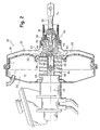
- FIG. 1 shows the assembly of a booster 10 for a motor vehicle.
- the brake booster 10 comprises a pneumatic brake booster 12 which is intended to actuate a master cylinder 14.
- the servomotor 12 comprises a rigid casing 16 within which is movable a transverse partition 18 sealingly delimits a front chamber 20, subjected to a first pressure "P 1 ", and a rear chamber 22 subjected to a second pressure P 2 "varying between the first pressure” P 1 "and a pressure” P a "greater than the first pressure” P 1 ".
- the servomotor 12 comprises a movable piston 24, integral with the movable partition 18, which has a front face 26 which is capable of biasing a primary piston of the master cylinder 14 by means of a reaction disc 28 .
- the reaction disc 28 is housed in a cage 30 which is interposed between the movable piston 24 and the primary piston (not shown).
- the servomotor 12 also comprises a control rod 32 which moves in the piston 24 selectively as a function of an axial input force exerted forwards against a return force exerted on the rod 32 by a return spring 34.
- the servomotor 12 comprises a plunger 36 which is arranged at the front of the control rod 32 in the piston 24 and which has at its rear end 38 at least one rear annular seat of a three-way valve 40 which is progressively movable. between a position in which, the control rod 32 being at rest, the front chamber 20 and the rear chamber 22 are in communication, and a position in which, the control rod 32 being actuated, the second pressure "P 2 " prevailing in the rear chamber 22 increases, the valve 40 putting the rear chamber 22 in communication with the pressure "P a " greater than the first pressure.
- the servomotor 12 comprises a feeler 42, arranged at the front end of the plunger 36 and passing through a bore 44 opening out of the piston 24 which, in the rest position of the control rod 32, is arranged at a determined jump distance from the disc 28, which is likely, when the control rod 32 is actuated according to an input force intensity greater than a first determined intensity, to travel the jump distance and to come into contact with the reaction disk 28 of in order to transmit to the plunger 42 and to the control rod 32 the reaction force of the master cylinder 14.
- the ratio of the surface of the reaction disk 28 in contact with the cage 30 and the surface of the probe 42 in contact with the reaction disk 28 determines in a known manner a first assistance ratio determined.
- the disadvantage of this known design is that, when the control rod is actuated rapidly according to an input force of intensity greater than the first determined intensity, the delay in equalizing the pressures between the front and rear chambers 22 does not allow the movable piston 24 to sufficiently assist the braking force of the driver who must also overcome the reaction force that the master cylinder 14 exerts on the rod 32 through the reaction disc 28.
- the cage 30 comprises at least one movable decompression wall which is capable, when the control rod 32 is actuated according to a force of input intensity greater than a second determined intensity greater than the first, to move to create in the cage 30 an additional volume in which a front portion of the reaction disk 28 is likely to expand next to the probe 42.
- a rear part of the reaction disk 28 is capable of decompressing locally at the level of the probe 42, which makes it possible to reduce the reaction force. transmitted to the probe 42 via the rear face of the reaction disc.
- the mobile decompression wall is generally part of a decompression device which is attached to the cage and which is interposed between the reaction disk and the primary piston of the master cylinder.
- This booster (not shown) conventionally comprises a housing secured to the primary piston of the master cylinder, one side of which is contiguous to the reaction disc and is pierced to allow the passage of a cylindrical decompression piston which is also arranged in contact with the reaction disk.
- the decompression piston is resiliently biased toward the reaction disc by a helical spring which is housed inside the housing and which is substantially of the same diameter as the decompression piston.
- This design has many disadvantages in terms of size.
- this design requires the use of a coil spring which is substantially the same diameter as the decompression piston. It is therefore impossible to reduce the diameter of the coil spring without reducing the diameter of the decompression piston which, therefore, no longer has a clean surface to create in the cage a decompression volume sufficient to bring adequate decompression of the reaction disc.
- a decompression piston of adequate size does not permit the use of a coil spring of diameter sufficiently small that the housing can for example be integrated in a push rod interposed between the cage and the primary piston of the master cylinder.
- the invention provides a brake booster 10 of the type described above comprising a compact decompression device.
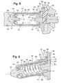
- the brake booster 10 is provided with a cage 30, formed in the piston 24, of which at least one mobile decompression wall 46 is capable, when the control rod 32 is actuated according to an intensity input force greater than a second determined intensity greater than the first, to move to create in the cage 30 an additional volume in which a front portion 48 of the reaction disk 28 is likely to expel to reduce the reaction force transmitted to the probe 42 via the rear face 50 of the reaction disc 28.
- the servomotor 12 comprises a rod 52 of independent thrust, which is interposed between the reaction disc 28 and the primary piston 54 of the master cylinder 14, and which comprises a rear section 56, a rear face 58 of which is arranged in contact with the reaction disc 28, and in which a slot 60 opening into the rear face 58 receives a conformal decompression piston 62 of transverse size "E" determined, which comprises at least two radial branches 64 and a rear face forms the movable wall 46 of decompression.
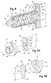
- FIGS. 7A and 7B show a first embodiment of a piston 62 comprising three radial branches 64 distributed angularly in a regular manner
- FIGS. 9A and 9B show a second embodiment of the invention comprising two radial branches 64 which extend radially to the periphery of the rear face 58 of the rear section 56.
- piston 62 could comprise a greater number of branches 64, for example four, five or six radial branches 64.
- the rod 52 of independent thrust also comprises a tubular front section 66, including a bore 68 which opens at the front end of the slot 60, and which has a diameter "D" less than the transverse size "E” determined receives a helical spring 70 receiving a rod 72 for returning the decompression piston 62.
- the return piston rod 72 of the decompression piston is of a diameter corresponding substantially to the inside diameter of the coil spring 70.
- the brake booster 10 proposes a maximum transverse decompression piston "E" 62 and a push rod 52 of minimum diameter, substantially close to the diameter "D" of its bore 68.
- the thrust rod 52 comprises a tubular front portion 67 which includes a portion of the front section 66, and a rear portion 57 which internally comprises the other portion of the front section 66, and therefore the other part of the bore 68, and the rear section 56.
- the rear section 56 comprises at least one face 74 which forms an axial stop for the return spring 70 of the piston 62 of FIG. decompression
- the face 74 arranged at the end of the slot 60, is angularly arranged between two consecutive limbs 64 of the decompression piston 62, and projects transversely into the bore 68.
- the associated rear portion 57 the piston 62 with three branches 64 of Figures 3 to 7B comprises three faces 74 distributed between the three branches of the light 60 corresponding to the three branches 64 of the piston 62
- the rear portion 57 associated with the piston 62 with two branches 64 of Figures 8 to 9B comprises two faces 74 distributed between the two branches of the slot 60 corresponding to the two legs 64 of the piston 62.
- the front section 66 comprises, in the rear portion 57, at least one face 76 which forms an axial stop for the decompression piston 62.
- the face 76 is arranged in the axial extension of at least one of the two branches 64 of the decompression piston 62, and projects into the interior of the slot 60.
- Each rear portion 57 therefore has as many abutment faces 76 as the piston 62 has branches 64.
- each branch 64 of the decompression piston 62 comprises at least a bearing face 78 for the coil spring 70, which is arranged along the diameter of the tubular front section 66.
- the faces 78 are distributed over all the branches 64 of the piston 62.
- the piston 62 of FIG. 7A thus comprises three faces 78 and the piston 62 of Figure 64 has a face 78 shaped as an annular shoulder face.
- the support of the spring 70 on the face 78 may be direct, but preferably the push rod 52 comprises a bearing washer 79 which is mounted between the coil spring 70 and the bearing face 78 of the piston 62 of decompression.
- This washer 79 has an outer diameter corresponding to that of the bore 68 of the front section and is of an inner diameter corresponding to that of the rod 72 for restoring the piston 62 of decompression
- the movable wall 46 is movable as shown in FIGS. 3 to 5.
- a zero input force, or intensity lower than a first determined intensity, is applied to the rod 32 control.
- the plunger 42 does not urge the reaction disk 28 and is arranged at a distance "d" of jump thereof.
- an input force is applied to the control rod 32 according to an input force intensity greater than the first determined intensity and less than a second determined intensity.
- the reaction disk 28 deforms and substantially fills the distance "d" of jump separating it from the probe 42 to transmit the input force to the primary piston 54 according to the first assistance ratio determined.
- the input force being lower than the calibration of the spring 70, the decompression piston 62 is not biased and remains in alignment with the rear face 58 of the section 56. probe 42 the entire reaction of the master cylinder 14.
- an input force is applied to the control rod 32 according to an input force intensity greater than the second determined intensity.
- the probe 42 urges the reaction disk 28 which overcomes the counterforce of the spring 70 and the decompression piston 62 sinks into the lumen 60 by locally decompressing the reaction disk 28 in contact with the probe 46.
- the input force is transmitted to the piston primary 54 according to the second assistance ratio determined which is greater than the first.
- the reaction disk 28 transmits to the probe 42 only a portion of the reaction of the master cylinder 14.
- each branch 64 of the decompression piston also comprises at least one axial abutment face 80 intended to cooperate with the axial abutment face 76 of the front section 66.
- the front portion 67 is crimped on a front end cylindrical bearing surface 82 of the rear portion 57 in a variable axial position making it possible to adjust the preload of the coil spring 70.
- a shim 84 may be interposed between parts 67 and 57.
- the front portion could be tightly mounted in a front end bore 88 of the rear portion 57.
- the preload of the spring 70 is defined by the depth of the fitting, which can be limited by a shim 86 housed at the bottom of the bore 88.
- the invention makes it possible to take advantage of the tubular design of the front part.
- the tubular front portion 67 receives at its front end an axial finger 90, which is for example crimped into a conformed stamped bearing 92 of the front end of the front portion 67, and which is intended to allow the support of the push rod 52 in a bore 91 of the primary piston 14.
- the stamped bearing 92 defines in the front portion 67 a bowl 94 for supporting the spring 70.
Landscapes
- Engineering & Computer Science (AREA)
- Transportation (AREA)
- Mechanical Engineering (AREA)
- Braking Systems And Boosters (AREA)
- Actuator (AREA)
- Braking Arrangements (AREA)
- Pistons, Piston Rings, And Cylinders (AREA)
Claims (12)
- Servobremse (10) für ein Kraftfahrzeug, vom Typ, der einen pneumatischen Servomotor (12) zur Bremsunterstützung aufweist, welcher einen Hauptzylinder (14) betätigt,
vom Typ, bei dem der Servomotor (12) ein starres Gehäuse (16) aufweist, in dem eine quer verlaufende Wand (18) beweglich ist, die in dichter Weise eine vordere Kammer (20), die einem ersten Druck (P1) ausgesetzt ist, und eine hintere Kammer (22) begrenzt, die einem zweiten Druck (P2) ausgesetzt ist, welcher zwischen dem ersten Druck (P1) und einem Druck (Pa) variiert, der höher ist als der erste Druck (P1),
vom Typ, bei dem der Servomotor (12) einen beweglichen, fest mit der beweglichen Wand (18) verbundenen Kolben (24) aufweist, der eine vordere Fläche (26) aufweist, die einen Primärkolben (54) des Hauptzylinders (14) mittels einer Reaktionsscheibe (28) beaufschlagen kann, welche in einem Halter (30) angeordnet ist, der zwischen dem beweglichen Kolben (24) und dem Primärkolben (54) angeordnet ist,
vom Typ, bei dem der Servomotor (12) eine Steuerstange (32) aufweist, die sich im Kolben (24) selektiv in Abhängigkeit von einer axialen Eingangskraft verlagert, welche entgegen einer durch eine Rückstellfeder (34) auf die Stange (32) ausgeübten Rückstellkraft nach vorne ausgeübt wird,
vom Typ, bei dem der Servomotor (12) einen Tauchkolben (36) aufweist, der im Kolben (24) im vorderen Teil der Steuerstange (32) angeordnet ist und an seinem hinteren Ende (38) mindestens einen ringförmigen, hinteren Sitz eines Dreiwegeventils (40) aufweist, das progressiv zwischen einer Position, in der die vordere Kammer (20) und die hinteren Kammer (22) verbunden sind, da sich die Steuerstange (32) in der Ruheposition befindet, und einer Position beweglich ist, in der der zweite, in der hinteren Kammer (22) herrschende Druck (P2) steigt, da die Steuerstange (32) betätigt wird, wobei das Ventil (40) die hintere Kammer (22) mit dem Druck (Pa) verbindet, der höher ist als der ersten Druck (P1), und
vom Typ, bei dem der Servomotor (12) einen Taster (42) aufweist, der am vorderen Ende des Tauchkolbens (36) angeordnet ist und eine Bohrung (44) durchquert, die aus dem Kolben (24) ausgeht, der in der Ruheposition der Steuerstange (32) in einer bestimmten Sprungentfernung (d) von der Reaktionsscheibe (28) angeordnet ist, und der mit der Reaktionsscheibe (28) in Kontakt gelangen kann, wenn die Steuerstange (32) gemäß einer Eingangskraft betätigt wird, deren Stärke größer ist als eine erste bestimmte Stärke, so dass dem Tauchkolben (36) und der Steuerstange (32) die Reaktionskraft des Hauptzylinders (14) übertragen wird, wobei das Verhältnis zwischen der Oberfläche der Reaktionsscheibe (28), die den Halter (30) berührt, und der Oberfläche des Tasters (42) ein erstes bestimmtes Unterstützungsverhältnis bestimmt,
und vom Typ, bei dem der Halter (30) mindestens eine bewegliche Dekompressionswand (46) aufweist, die sich verlagern kann, wenn die Steuerstange (32) gemäß einer Eingangskraft betätigt wird, deren Stärke größer ist als eine zweite bestimmte Stärke, welche größer ist als die erste, um im Halter (30) ein zusätzliches Volumen zu bilden, in dem sich ein vorderer Teil (48) der Reaktionsscheibe (28) ausdehnen kann, um die Reaktionskraft zu verringern, die mittels der hinteren Fläche (50) der Reaktionsscheibe (28) auf den Taster (42) übertragen wird, wobei das Verhältnis zwischen der Oberfläche der Reaktionsscheibe (28), die den Halter (30) berührt, und der Oberfläche des Tasters (42) ein zweites Unterstützungsverhältnis bestimmt, das größer ist als das erste,
dadurch gekennzeichnet, dass sie eine unabhängige Schubstange (52) aufweist, die zwischen der Reaktionsscheibe (28) und dem Primärkolben (54) des Hauptzylinders angeordnet ist und folgendes aufweist:- einen hinteren Abschnitt (56), bei dem eine hintere Fläche (58) so angeordnet ist, dass sie die Reaktionsscheibe (28) berührt, und bei dem ein in die hintere Fläche (58) mündendes Langloch (60) einen konformen Dekompressionskolben (62) mit bestimmten Querabmessungen (E) aufnimmt, der mindestens zwei radiale Arme (64) aufweist und bei dem eine hintere Fläche die bewegliche Dekompressionswand (46) bildet,- einen röhrenförmigen vorderen Abschnitt (66), bei dem eine Bohrung (68), die am vorderen Ende des Langlochs (60) mündet und einen Durchmesser (D) besitzt, der kleiner ist als die bestimmten Querabmessungen (E), eine Spiralfeder (70) aufnimmt, welche eine Stange (72) zum Zurückstellen des Dekompressionskolbens (62) aufnimmt,um einen Dekompressionskolben (62) mit maximalen Querabmessungen (E) und eine Schubstange (52) mit minimalem Durchmesser vorzuschlagen. - Servobremse (10) nach Anspruch 1, dadurch gekennzeichnet, dass an der Verbindungsstelle zwischen dem vorderen Abschnitt (66) und dem hinteren Abschnitt (56)- der hintere Abschnitt (56) mindestens eine Fläche (74) aufweist, die einen axialen Anschlag für die Feder (70) zum Zurückstellen des Dekompressionskolbens (62) bildet, die winkelmäßig zwischen zwei aufeinander folgenden Armen (64) des Dekompressionskolbens (62) angeordnet ist und die quer im Inneren der Bohrung (68) hervorsteht,- der vordere Abschnitt (66) mindestens eine Fläche (76) aufweist, die einen axialen Anschlag für den Dekompressionskolben (62) bildet, die in der axialen Verlängerung mindestens eines der beiden Arme (64) des Dekompressionskolbens (62) angeordnet ist und die quer im Inneren des Langlochs (60) hervorsteht.
- Servobremse (10) nach Anspruch 2, dadurch gekennzeichnet, dass das vordere Ende jedes Arms (64) des Dekompressionskolbens (62) mindestens eine Anlagefläche (78) für die Spiralfeder (70) aufweist, die gemäß dem Durchmesser (D) des röhrenförmigen vorderen Abschnitts (66) angeordnet ist.
- Servobremse (10) nach Anspruch 2 oder 3, dadurch gekennzeichnet, dass das vordere Ende jedes Arms (64) des Dekompressionskolbens mindestens eine axiale Anschlagfläche (80) aufweist, welche mit der axialen Anschlagfläche (76) des vorderen Abschnitts (66) zusammenwirken soll.
- Servobremse (10) nach einem der Ansprüche 1 bis 4, dadurch gekennzeichnet, dass die Stange (72) zum Zurückstellen des Dekompressionskolbens (62) einen Durchmesser besitzt, der im Wesentlichen dem Innendurchmesser der Spiralfeder (70) entspricht.
- Servobremse (10) nach einem der Ansprüche 3 bis 5, dadurch gekennzeichnet, dass die Schubstange (52) eine Anlagescheibe (79) aufweist, die zwischen der Spiralfeder (70) und der Anlagefläche (78) des Dekompressionskolbens (62) angeordnet ist, deren Außendurchmesser dem der Bohrung (68) des vorderen Abschnitts (66) entspricht und deren Innendurchmesser dem der Stange (72) zum Zurückstellen des Dekompressionskolbens (62) entspricht.
- Servobremse (10) nach einem der Ansprüche 1 bis 6, dadurch gekennzeichnet, dass die Schubstange (52) folgendes aufweist:- einen röhrenförmigen vorderen Teil (67), der einen Teil des vorderen Abschnitts (66) aufweist,- einen hinteren Teil (57), der innen den anderen Teil des vorderen Abschnitts (66) und den hinteren Abschnitt (56) aufweist.
- Servobremse (10) nach dem vorhergehenden Anspruch, dadurch gekennzeichnet, dass der vordere Teil (67) so angebracht ist, dass er in einer Bohrung (88) am vorderen Ende des hinteren Teils (57) geklemmt ist.
- Servobremse (10) nach Anspruch 7, dadurch gekennzeichnet, dass der vordere Teil (67) gemäß einer variablen axialen Position, die das Einstellen der Vorspannung der Spiralfeder (70) ermöglicht, auf eine zylindrische Auflagefläche (82) am vorderen Ende des hinteren Teils (57) gefalzt ist.
- Servobremse (10) nach einem der Ansprüche 7 bis 9, dadurch gekennzeichnet, dass der röhrenförmige vordere Teil (67) an seinem vorderen Ende einen axialen Zapfen (90) aufweist, der das Anliegen der Schubstange (52) am Primärkolben (54) des Hauptzylinders (14) ermöglichen soll.
- Servobremse (10) nach einem der Ansprüche 1 bis 10, dadurch gekennzeichnet, dass der Dekompressionskolben (62) drei Arme (64) aufweist, die winkelmäßig gleichmäßig verteilt sind.
- Servobremse (10) nach einem der Ansprüche 1 bis 10, dadurch gekennzeichnet, dass der Dekompressionskolben (62) zwei entgegengesetzte Arme (64) aufweist, die sich radial bis zum Umfang der hinteren Fläche (58) des hinteren Abschnitts (56) erstrecken.
Applications Claiming Priority (3)
| Application Number | Priority Date | Filing Date | Title |
|---|---|---|---|
| FR0300884A FR2850343B1 (fr) | 2003-01-27 | 2003-01-27 | Servofrein comportant un piston de decompression integre a la tige de poussee |
| FR0300884 | 2003-01-27 | ||
| PCT/EP2004/000619 WO2004067345A1 (fr) | 2003-01-27 | 2004-01-26 | Servofrein comportant un piston de decompression integre a la tige de poussee |
Publications (2)
| Publication Number | Publication Date |
|---|---|
| EP1590222A1 EP1590222A1 (de) | 2005-11-02 |
| EP1590222B1 true EP1590222B1 (de) | 2006-05-17 |
Family
ID=32669247
Family Applications (1)
| Application Number | Title | Priority Date | Filing Date |
|---|---|---|---|
| EP04705089A Expired - Lifetime EP1590222B1 (de) | 2003-01-27 | 2004-01-26 | Servobremssystem mit in der druckstange im hauptzylinderintegriertem dekompressionskolben |
Country Status (9)
| Country | Link |
|---|---|
| US (1) | US7100997B2 (de) |
| EP (1) | EP1590222B1 (de) |
| JP (1) | JP2006515823A (de) |
| CN (1) | CN1330519C (de) |
| AT (1) | ATE326374T1 (de) |
| DE (1) | DE602004000911T2 (de) |
| ES (1) | ES2263133T3 (de) |
| FR (1) | FR2850343B1 (de) |
| WO (1) | WO2004067345A1 (de) |
Families Citing this family (4)
| Publication number | Priority date | Publication date | Assignee | Title |
|---|---|---|---|---|
| FR2850344B1 (fr) * | 2003-01-27 | 2005-04-08 | Bosch Sist De Frenado Sl | Servofrein comportant un piston de decompression integre au piston primaire du maitre-cylindre |
| US7930969B1 (en) * | 2008-07-31 | 2011-04-26 | Robert Bosch Gmbh | Brake booster with dual rate assist |
| DE102010038918A1 (de) * | 2010-05-20 | 2011-11-24 | Robert Bosch Gmbh | Bremskraftverstärker sowie Verfahren zu dessen Betrieb |
| US12168429B2 (en) | 2021-09-17 | 2024-12-17 | Robert Bosch Gmbh | Brake booster assembly and pushrod-pedal coupler |
Family Cites Families (9)
| Publication number | Priority date | Publication date | Assignee | Title |
|---|---|---|---|---|
| CN2087586U (zh) * | 1990-09-24 | 1991-10-30 | 梁宗涛 | 大型载重车液压真空伺服制动装置 |
| DE19545947C2 (de) * | 1995-12-08 | 2002-08-22 | Lucas Ind Plc | Bremskraftverstärker und Montageverfahren hierfür |
| FR2765173B1 (fr) * | 1997-06-27 | 1999-08-27 | Bosch Sist De Frenado Sl | Maitre-cylindre a reaction hydraulique dynamique et a piston flottant |
| FR2784642B1 (fr) * | 1998-10-20 | 2000-12-15 | Bosch Sist De Frenado Sl | Maitre-cylindre a reaction hydraulique et a effort d'entree accru |
| DE19917281A1 (de) * | 1999-04-16 | 2000-10-26 | Continental Teves Ag & Co Ohg | Bremskraftübertragungsmechanismus für einen Bremskraftverstärker |
| FR2820388B1 (fr) * | 2001-02-07 | 2004-05-28 | Bosch Sist De Frenado Sl | Dispositif de reaction pour servomoteur pneumatique d'assistance au freinage et servomoteur pneumatique d'assistance au freinage comportant un tel dispositif |
| DE10113292A1 (de) * | 2001-03-16 | 2002-09-19 | Continental Teves Ag & Co Ohg | Bremskraftübertragungseinrichtung für einen Bremskraftverstärker |
| JP2003089353A (ja) * | 2001-09-18 | 2003-03-25 | Bosch Automotive Systems Corp | 倍力装置 |
| FR2850344B1 (fr) * | 2003-01-27 | 2005-04-08 | Bosch Sist De Frenado Sl | Servofrein comportant un piston de decompression integre au piston primaire du maitre-cylindre |
-
2003
- 2003-01-27 FR FR0300884A patent/FR2850343B1/fr not_active Expired - Fee Related
-
2004
- 2004-01-26 US US10/542,097 patent/US7100997B2/en not_active Expired - Fee Related
- 2004-01-26 CN CNB2004800029606A patent/CN1330519C/zh not_active Expired - Fee Related
- 2004-01-26 ES ES04705089T patent/ES2263133T3/es not_active Expired - Lifetime
- 2004-01-26 DE DE602004000911T patent/DE602004000911T2/de not_active Expired - Lifetime
- 2004-01-26 JP JP2006501601A patent/JP2006515823A/ja active Pending
- 2004-01-26 WO PCT/EP2004/000619 patent/WO2004067345A1/fr not_active Ceased
- 2004-01-26 EP EP04705089A patent/EP1590222B1/de not_active Expired - Lifetime
- 2004-01-26 AT AT04705089T patent/ATE326374T1/de not_active IP Right Cessation
Also Published As
| Publication number | Publication date |
|---|---|
| FR2850343B1 (fr) | 2005-04-08 |
| EP1590222A1 (de) | 2005-11-02 |
| DE602004000911T2 (de) | 2007-01-25 |
| US20060055236A1 (en) | 2006-03-16 |
| WO2004067345A1 (fr) | 2004-08-12 |
| DE602004000911D1 (de) | 2006-06-22 |
| US7100997B2 (en) | 2006-09-05 |
| ES2263133T3 (es) | 2006-12-01 |
| CN1330519C (zh) | 2007-08-08 |
| ATE326374T1 (de) | 2006-06-15 |
| CN1741929A (zh) | 2006-03-01 |
| JP2006515823A (ja) | 2006-06-08 |
| FR2850343A1 (fr) | 2004-07-30 |
Similar Documents
| Publication | Publication Date | Title |
|---|---|---|
| EP1538050B1 (de) | Bremskraftverstärker mit einem in der Stösselstange integrierten Dekompressionskolben aus einem elastischen Material | |
| EP0501843B1 (de) | Bremskraftverstärker mit einstellbarem Schwellenwert und Verfahren zum Regeln des Schwellenwertes | |
| FR2751602A1 (fr) | Dispositif de freinage assiste a rapport d'assistance variable | |
| EP1590222B1 (de) | Servobremssystem mit in der druckstange im hauptzylinderintegriertem dekompressionskolben | |
| EP1590221B1 (de) | Servobremssystem mit im primärkolben im hauptzylinderintegriertem dekompressionskolben | |
| EP0779870B1 (de) | Pneumatischer bremskraftverstärker | |
| FR2684059A1 (fr) | Servomoteur pneumatique. | |
| EP1080002B1 (de) | Pneumatischer bremskraftverstärker mit schwimmender reaktionsscheibe und dynamisch annulierbarer reaktion | |
| EP1397279A1 (de) | Bremskraftverstärker mit zwei unterschiedlichen festen und veränderlichen schwellenwerten | |
| EP1351850B1 (de) | Bremskraftverstärker mit einen hohen schwellwert aufweisendem sicherheitsventil | |
| FR2809066A1 (fr) | Servomoteur comportant un embrayage unidirectionnel expansible | |
| EP0687229B1 (de) | Hilfskraftbremsvorrichtung mit vereinfachter automatischer steuerung | |
| EP0993399A1 (de) | Hauptzylinder mit dynamischer hydraulischer reaktion und mit schwimmendem kolben | |
| EP1361129B1 (de) | Mechanische Sicherung für einen pneumatischen Bremskraftverstärker | |
| EP1325853B1 (de) | Pneumatischer Bremsservo mit reduzierter Reaktion | |
| EP0991556B1 (de) | Pneumatischer bremskraftverstärker mit verbessertem ventil | |
| FR2867138A1 (fr) | Servofrein comportant un piston de decompression integre au piston primaire du maitre cylindre | |
| EP2058196B1 (de) | Taster für Hilfsservomotor zur Bremsung | |
| FR2918627A1 (fr) | Servomoteur d'assistance au freinage pour systeme de freinage de vehicule automobile. | |
| FR2638691A1 (fr) | Systeme de freinage hydraulique assiste, et servomoteur d'assistance et valve de commande adaptes a un tel systeme | |
| EP1522478A1 (de) | Unterdruckbremskraftverstärker mit verkürztem Leerweg und Bremssystem mit einem solchen Verstärker | |
| FR2925440A1 (fr) | Servofrein comportant un piston de decompression integre a un maitre-cylindre a reaction reduite. | |
| FR2736605A1 (fr) | Dispositif de freinage assiste a temps de reponse ameliore | |
| FR2824034A1 (fr) | Servomoteur comportant une cle de coincement | |
| FR2922174A1 (fr) | Systeme de freinage d'urgence pour vehicule automobile. |
Legal Events
| Date | Code | Title | Description |
|---|---|---|---|
| PUAI | Public reference made under article 153(3) epc to a published international application that has entered the european phase |
Free format text: ORIGINAL CODE: 0009012 |
|
| 17P | Request for examination filed |
Effective date: 20050829 |
|
| AK | Designated contracting states |
Kind code of ref document: A1 Designated state(s): AT BE BG CH CY CZ DE DK EE ES FI FR GB GR HU IE IT LI LU MC NL PT RO SE SI SK TR |
|
| AX | Request for extension of the european patent |
Extension state: AL LT LV MK |
|
| GRAP | Despatch of communication of intention to grant a patent |
Free format text: ORIGINAL CODE: EPIDOSNIGR1 |
|
| DAX | Request for extension of the european patent (deleted) | ||
| GRAS | Grant fee paid |
Free format text: ORIGINAL CODE: EPIDOSNIGR3 |
|
| GRAA | (expected) grant |
Free format text: ORIGINAL CODE: 0009210 |
|
| AK | Designated contracting states |
Kind code of ref document: B1 Designated state(s): AT BE BG CH CY CZ DE DK EE ES FI FR GB GR HU IE IT LI LU MC NL PT RO SE SI SK TR |
|
| PG25 | Lapsed in a contracting state [announced via postgrant information from national office to epo] |
Ref country code: AT Free format text: LAPSE BECAUSE OF FAILURE TO SUBMIT A TRANSLATION OF THE DESCRIPTION OR TO PAY THE FEE WITHIN THE PRESCRIBED TIME-LIMIT Effective date: 20060517 Ref country code: IT Free format text: LAPSE BECAUSE OF FAILURE TO SUBMIT A TRANSLATION OF THE DESCRIPTION OR TO PAY THE FEE WITHIN THE PRESCRIBED TIME-LIMIT;WARNING: LAPSES OF ITALIAN PATENTS WITH EFFECTIVE DATE BEFORE 2007 MAY HAVE OCCURRED AT ANY TIME BEFORE 2007. THE CORRECT EFFECTIVE DATE MAY BE DIFFERENT FROM THE ONE RECORDED. Effective date: 20060517 Ref country code: CZ Free format text: LAPSE BECAUSE OF FAILURE TO SUBMIT A TRANSLATION OF THE DESCRIPTION OR TO PAY THE FEE WITHIN THE PRESCRIBED TIME-LIMIT Effective date: 20060517 Ref country code: SI Free format text: LAPSE BECAUSE OF FAILURE TO SUBMIT A TRANSLATION OF THE DESCRIPTION OR TO PAY THE FEE WITHIN THE PRESCRIBED TIME-LIMIT Effective date: 20060517 Ref country code: NL Free format text: LAPSE BECAUSE OF FAILURE TO SUBMIT A TRANSLATION OF THE DESCRIPTION OR TO PAY THE FEE WITHIN THE PRESCRIBED TIME-LIMIT Effective date: 20060517 Ref country code: RO Free format text: LAPSE BECAUSE OF FAILURE TO SUBMIT A TRANSLATION OF THE DESCRIPTION OR TO PAY THE FEE WITHIN THE PRESCRIBED TIME-LIMIT Effective date: 20060517 Ref country code: SK Free format text: LAPSE BECAUSE OF FAILURE TO SUBMIT A TRANSLATION OF THE DESCRIPTION OR TO PAY THE FEE WITHIN THE PRESCRIBED TIME-LIMIT Effective date: 20060517 Ref country code: IE Free format text: LAPSE BECAUSE OF FAILURE TO SUBMIT A TRANSLATION OF THE DESCRIPTION OR TO PAY THE FEE WITHIN THE PRESCRIBED TIME-LIMIT Effective date: 20060517 Ref country code: FI Free format text: LAPSE BECAUSE OF FAILURE TO SUBMIT A TRANSLATION OF THE DESCRIPTION OR TO PAY THE FEE WITHIN THE PRESCRIBED TIME-LIMIT Effective date: 20060517 |
|
| REG | Reference to a national code |
Ref country code: GB Ref legal event code: FG4D Free format text: NOT ENGLISH |
|
| REG | Reference to a national code |
Ref country code: CH Ref legal event code: EP |
|
| REG | Reference to a national code |
Ref country code: IE Ref legal event code: FG4D Free format text: LANGUAGE OF EP DOCUMENT: FRENCH |
|
| REF | Corresponds to: |
Ref document number: 602004000911 Country of ref document: DE Date of ref document: 20060622 Kind code of ref document: P |
|
| PG25 | Lapsed in a contracting state [announced via postgrant information from national office to epo] |
Ref country code: SE Free format text: LAPSE BECAUSE OF FAILURE TO SUBMIT A TRANSLATION OF THE DESCRIPTION OR TO PAY THE FEE WITHIN THE PRESCRIBED TIME-LIMIT Effective date: 20060817 Ref country code: DK Free format text: LAPSE BECAUSE OF FAILURE TO SUBMIT A TRANSLATION OF THE DESCRIPTION OR TO PAY THE FEE WITHIN THE PRESCRIBED TIME-LIMIT Effective date: 20060817 |
|
| PG25 | Lapsed in a contracting state [announced via postgrant information from national office to epo] |
Ref country code: PT Free format text: LAPSE BECAUSE OF FAILURE TO SUBMIT A TRANSLATION OF THE DESCRIPTION OR TO PAY THE FEE WITHIN THE PRESCRIBED TIME-LIMIT Effective date: 20061017 |
|
| NLV1 | Nl: lapsed or annulled due to failure to fulfill the requirements of art. 29p and 29m of the patents act | ||
| REG | Reference to a national code |
Ref country code: ES Ref legal event code: FG2A Ref document number: 2263133 Country of ref document: ES Kind code of ref document: T3 |
|
| REG | Reference to a national code |
Ref country code: IE Ref legal event code: FD4D |
|
| PG25 | Lapsed in a contracting state [announced via postgrant information from national office to epo] |
Ref country code: MC Free format text: LAPSE BECAUSE OF NON-PAYMENT OF DUE FEES Effective date: 20070131 |
|
| PLBE | No opposition filed within time limit |
Free format text: ORIGINAL CODE: 0009261 |
|
| STAA | Information on the status of an ep patent application or granted ep patent |
Free format text: STATUS: NO OPPOSITION FILED WITHIN TIME LIMIT |
|
| 26N | No opposition filed |
Effective date: 20070220 |
|
| BERE | Be: lapsed |
Owner name: BOSCH SISTEMAS DE FRENADO, S.L. Effective date: 20070131 |
|
| PG25 | Lapsed in a contracting state [announced via postgrant information from national office to epo] |
Ref country code: BE Free format text: LAPSE BECAUSE OF NON-PAYMENT OF DUE FEES Effective date: 20070131 |
|
| PG25 | Lapsed in a contracting state [announced via postgrant information from national office to epo] |
Ref country code: GR Free format text: LAPSE BECAUSE OF FAILURE TO SUBMIT A TRANSLATION OF THE DESCRIPTION OR TO PAY THE FEE WITHIN THE PRESCRIBED TIME-LIMIT Effective date: 20060818 |
|
| PG25 | Lapsed in a contracting state [announced via postgrant information from national office to epo] |
Ref country code: BG Free format text: LAPSE BECAUSE OF FAILURE TO SUBMIT A TRANSLATION OF THE DESCRIPTION OR TO PAY THE FEE WITHIN THE PRESCRIBED TIME-LIMIT Effective date: 20060817 |
|
| PG25 | Lapsed in a contracting state [announced via postgrant information from national office to epo] |
Ref country code: EE Free format text: LAPSE BECAUSE OF FAILURE TO SUBMIT A TRANSLATION OF THE DESCRIPTION OR TO PAY THE FEE WITHIN THE PRESCRIBED TIME-LIMIT Effective date: 20060517 |
|
| REG | Reference to a national code |
Ref country code: CH Ref legal event code: PL |
|
| PG25 | Lapsed in a contracting state [announced via postgrant information from national office to epo] |
Ref country code: LI Free format text: LAPSE BECAUSE OF NON-PAYMENT OF DUE FEES Effective date: 20080131 Ref country code: CH Free format text: LAPSE BECAUSE OF NON-PAYMENT OF DUE FEES Effective date: 20080131 |
|
| PG25 | Lapsed in a contracting state [announced via postgrant information from national office to epo] |
Ref country code: LU Free format text: LAPSE BECAUSE OF NON-PAYMENT OF DUE FEES Effective date: 20070126 Ref country code: CY Free format text: LAPSE BECAUSE OF FAILURE TO SUBMIT A TRANSLATION OF THE DESCRIPTION OR TO PAY THE FEE WITHIN THE PRESCRIBED TIME-LIMIT Effective date: 20060517 |
|
| PG25 | Lapsed in a contracting state [announced via postgrant information from national office to epo] |
Ref country code: HU Free format text: LAPSE BECAUSE OF FAILURE TO SUBMIT A TRANSLATION OF THE DESCRIPTION OR TO PAY THE FEE WITHIN THE PRESCRIBED TIME-LIMIT Effective date: 20061118 |
|
| REG | Reference to a national code |
Ref country code: FR Ref legal event code: PLFP Year of fee payment: 13 |
|
| PGFP | Annual fee paid to national office [announced via postgrant information from national office to epo] |
Ref country code: ES Payment date: 20160122 Year of fee payment: 13 Ref country code: IT Payment date: 20160122 Year of fee payment: 13 Ref country code: TR Payment date: 20160119 Year of fee payment: 13 |
|
| PGFP | Annual fee paid to national office [announced via postgrant information from national office to epo] |
Ref country code: GB Payment date: 20160122 Year of fee payment: 13 Ref country code: FR Payment date: 20160121 Year of fee payment: 13 |
|
| GBPC | Gb: european patent ceased through non-payment of renewal fee |
Effective date: 20170126 |
|
| REG | Reference to a national code |
Ref country code: FR Ref legal event code: ST Effective date: 20170929 |
|
| PG25 | Lapsed in a contracting state [announced via postgrant information from national office to epo] |
Ref country code: FR Free format text: LAPSE BECAUSE OF NON-PAYMENT OF DUE FEES Effective date: 20170131 |
|
| PG25 | Lapsed in a contracting state [announced via postgrant information from national office to epo] |
Ref country code: GB Free format text: LAPSE BECAUSE OF NON-PAYMENT OF DUE FEES Effective date: 20170126 |
|
| PG25 | Lapsed in a contracting state [announced via postgrant information from national office to epo] |
Ref country code: IT Free format text: LAPSE BECAUSE OF NON-PAYMENT OF DUE FEES Effective date: 20170126 |
|
| PGFP | Annual fee paid to national office [announced via postgrant information from national office to epo] |
Ref country code: DE Payment date: 20180308 Year of fee payment: 15 |
|
| PG25 | Lapsed in a contracting state [announced via postgrant information from national office to epo] |
Ref country code: ES Free format text: LAPSE BECAUSE OF NON-PAYMENT OF DUE FEES Effective date: 20170127 |
|
| REG | Reference to a national code |
Ref country code: ES Ref legal event code: FD2A Effective date: 20180626 |
|
| REG | Reference to a national code |
Ref country code: DE Ref legal event code: R119 Ref document number: 602004000911 Country of ref document: DE |
|
| PG25 | Lapsed in a contracting state [announced via postgrant information from national office to epo] |
Ref country code: DE Free format text: LAPSE BECAUSE OF NON-PAYMENT OF DUE FEES Effective date: 20190801 |
|
| PG25 | Lapsed in a contracting state [announced via postgrant information from national office to epo] |
Ref country code: TR Free format text: LAPSE BECAUSE OF NON-PAYMENT OF DUE FEES Effective date: 20170126 |