EP1589299A2 - Heat pump and compressor discharge pressure controlling apparatus for the same - Google Patents
Heat pump and compressor discharge pressure controlling apparatus for the same Download PDFInfo
- Publication number
- EP1589299A2 EP1589299A2 EP05008786A EP05008786A EP1589299A2 EP 1589299 A2 EP1589299 A2 EP 1589299A2 EP 05008786 A EP05008786 A EP 05008786A EP 05008786 A EP05008786 A EP 05008786A EP 1589299 A2 EP1589299 A2 EP 1589299A2
- Authority
- EP
- European Patent Office
- Prior art keywords
- compressor
- refrigerant
- heat exchanger
- indoor
- outdoor
- Prior art date
- Legal status (The legal status is an assumption and is not a legal conclusion. Google has not performed a legal analysis and makes no representation as to the accuracy of the status listed.)
- Withdrawn
Links
Images


Classifications
-
- F—MECHANICAL ENGINEERING; LIGHTING; HEATING; WEAPONS; BLASTING
- F25—REFRIGERATION OR COOLING; COMBINED HEATING AND REFRIGERATION SYSTEMS; HEAT PUMP SYSTEMS; MANUFACTURE OR STORAGE OF ICE; LIQUEFACTION SOLIDIFICATION OF GASES
- F25B—REFRIGERATION MACHINES, PLANTS OR SYSTEMS; COMBINED HEATING AND REFRIGERATION SYSTEMS; HEAT PUMP SYSTEMS
- F25B13/00—Compression machines, plants or systems, with reversible cycle
-
- F—MECHANICAL ENGINEERING; LIGHTING; HEATING; WEAPONS; BLASTING
- F25—REFRIGERATION OR COOLING; COMBINED HEATING AND REFRIGERATION SYSTEMS; HEAT PUMP SYSTEMS; MANUFACTURE OR STORAGE OF ICE; LIQUEFACTION SOLIDIFICATION OF GASES
- F25B—REFRIGERATION MACHINES, PLANTS OR SYSTEMS; COMBINED HEATING AND REFRIGERATION SYSTEMS; HEAT PUMP SYSTEMS
- F25B40/00—Subcoolers, desuperheaters or superheaters
-
- F—MECHANICAL ENGINEERING; LIGHTING; HEATING; WEAPONS; BLASTING
- F25—REFRIGERATION OR COOLING; COMBINED HEATING AND REFRIGERATION SYSTEMS; HEAT PUMP SYSTEMS; MANUFACTURE OR STORAGE OF ICE; LIQUEFACTION SOLIDIFICATION OF GASES
- F25B—REFRIGERATION MACHINES, PLANTS OR SYSTEMS; COMBINED HEATING AND REFRIGERATION SYSTEMS; HEAT PUMP SYSTEMS
- F25B49/00—Arrangement or mounting of control or safety devices
- F25B49/005—Arrangement or mounting of control or safety devices of safety devices
-
- F—MECHANICAL ENGINEERING; LIGHTING; HEATING; WEAPONS; BLASTING
- F25—REFRIGERATION OR COOLING; COMBINED HEATING AND REFRIGERATION SYSTEMS; HEAT PUMP SYSTEMS; MANUFACTURE OR STORAGE OF ICE; LIQUEFACTION SOLIDIFICATION OF GASES
- F25B—REFRIGERATION MACHINES, PLANTS OR SYSTEMS; COMBINED HEATING AND REFRIGERATION SYSTEMS; HEAT PUMP SYSTEMS
- F25B49/00—Arrangement or mounting of control or safety devices
- F25B49/02—Arrangement or mounting of control or safety devices for compression type machines, plants or systems
- F25B49/022—Compressor control arrangements
-
- F—MECHANICAL ENGINEERING; LIGHTING; HEATING; WEAPONS; BLASTING
- F25—REFRIGERATION OR COOLING; COMBINED HEATING AND REFRIGERATION SYSTEMS; HEAT PUMP SYSTEMS; MANUFACTURE OR STORAGE OF ICE; LIQUEFACTION SOLIDIFICATION OF GASES
- F25B—REFRIGERATION MACHINES, PLANTS OR SYSTEMS; COMBINED HEATING AND REFRIGERATION SYSTEMS; HEAT PUMP SYSTEMS
- F25B2400/00—General features or devices for refrigeration machines, plants or systems, combined heating and refrigeration systems or heat-pump systems, i.e. not limited to a particular subgroup of F25B
- F25B2400/04—Refrigeration circuit bypassing means
- F25B2400/0403—Refrigeration circuit bypassing means for the condenser
-
- F—MECHANICAL ENGINEERING; LIGHTING; HEATING; WEAPONS; BLASTING
- F25—REFRIGERATION OR COOLING; COMBINED HEATING AND REFRIGERATION SYSTEMS; HEAT PUMP SYSTEMS; MANUFACTURE OR STORAGE OF ICE; LIQUEFACTION SOLIDIFICATION OF GASES
- F25B—REFRIGERATION MACHINES, PLANTS OR SYSTEMS; COMBINED HEATING AND REFRIGERATION SYSTEMS; HEAT PUMP SYSTEMS
- F25B2400/00—General features or devices for refrigeration machines, plants or systems, combined heating and refrigeration systems or heat-pump systems, i.e. not limited to a particular subgroup of F25B
- F25B2400/04—Refrigeration circuit bypassing means
- F25B2400/0411—Refrigeration circuit bypassing means for the expansion valve or capillary tube
-
- F—MECHANICAL ENGINEERING; LIGHTING; HEATING; WEAPONS; BLASTING
- F25—REFRIGERATION OR COOLING; COMBINED HEATING AND REFRIGERATION SYSTEMS; HEAT PUMP SYSTEMS; MANUFACTURE OR STORAGE OF ICE; LIQUEFACTION SOLIDIFICATION OF GASES
- F25B—REFRIGERATION MACHINES, PLANTS OR SYSTEMS; COMBINED HEATING AND REFRIGERATION SYSTEMS; HEAT PUMP SYSTEMS
- F25B2500/00—Problems to be solved
- F25B2500/24—Low amount of refrigerant in the system
-
- F—MECHANICAL ENGINEERING; LIGHTING; HEATING; WEAPONS; BLASTING
- F25—REFRIGERATION OR COOLING; COMBINED HEATING AND REFRIGERATION SYSTEMS; HEAT PUMP SYSTEMS; MANUFACTURE OR STORAGE OF ICE; LIQUEFACTION SOLIDIFICATION OF GASES
- F25B—REFRIGERATION MACHINES, PLANTS OR SYSTEMS; COMBINED HEATING AND REFRIGERATION SYSTEMS; HEAT PUMP SYSTEMS
- F25B2600/00—Control issues
- F25B2600/02—Compressor control
- F25B2600/026—Compressor control by controlling unloaders
- F25B2600/0261—Compressor control by controlling unloaders external to the compressor
-
- F—MECHANICAL ENGINEERING; LIGHTING; HEATING; WEAPONS; BLASTING
- F25—REFRIGERATION OR COOLING; COMBINED HEATING AND REFRIGERATION SYSTEMS; HEAT PUMP SYSTEMS; MANUFACTURE OR STORAGE OF ICE; LIQUEFACTION SOLIDIFICATION OF GASES
- F25B—REFRIGERATION MACHINES, PLANTS OR SYSTEMS; COMBINED HEATING AND REFRIGERATION SYSTEMS; HEAT PUMP SYSTEMS
- F25B2600/00—Control issues
- F25B2600/02—Compressor control
- F25B2600/027—Compressor control by controlling pressure
- F25B2600/0271—Compressor control by controlling pressure the discharge pressure
Definitions
- the present invention relates to a heat pump, and, more particularly, to a heat pump having an accumulator inlet side introducing pipe extending through a discharge pipe of a compressor in order to prevent the compressor from being damaged due to low-temperatures and low-pressure liquid refrigerant passing through an outdoor heat exchanger into a compressor, thereby preventing liquid refrigerant from entering into the accumulator and the compressor, maintaining the compressor discharge pressure to a predetermined pressure level, when the temperature of outdoor air is low or the load is excessive, to stabilize the compressor suction pressure, and control the liquid-compression phenomenon, when the outdoor heat exchanger is covered with frost as the temperature of the outdoor air is lower in winter, and therefore, no evaporation process is performed, to prevent the compressor from being damaged.
- the present invention relates to a compressor discharge pressure control apparatus for such a heat pump that is capable of decreasing the pressure and temperature of refrigerant discharged from the compressor to a set pressure and temperature levels, when the cooling load or heating load is excessive, to uniformly maintain the compressor discharge pressure and compressor suction pressure.
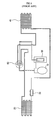
- FIG. 1 is a view schematically showing the structure of a conventional heat pump.
- the conventional heat pump comprises: a compressor 10 for compressing refrigerant into high-temperature and high-pressure gas refrigerant in a heating operation mode; a condenser, i.e., an indoor heat exchanger 20 for performing heat exchange between the refrigerant compressed by the compressor 10 and air (if the heat pump is an air-cooled type heat pump) to condense gas refrigerant into liquid refrigerant; an expansion valve 30 for expanding the high-temperature and high-pressure liquid refrigerant condensed by the indoor heat exchanger 20 into low-pressure gas refrigerant by a throttling expansion action; an outdoor heat exchanger 40 for evaporating the refrigerant expanded by the expansion valve 30, performing heat exchange between the refrigerant and air blown by a blower through the use of the latent heat of vaporization of the refrigerant to cool the air, and returning the gas refrigerant to the compressor 10; and an accumulator 50 for separating the refrigerant collected from the outdoor heat exchange
- the accumulator 50 serves to separate the refrigerant evaporated by the outdoor heat exchanger 40 into liquid refrigerant and gas refrigerant such that only the gas refrigerant is introduced into the compressor 10.
- the accumulator 50 serves to prevent the liquid refrigerant from entering into the compressor 10 such that the compressor 10 is prevented from being damaged due to compression of the liquid refrigerant.
- the heat pump is a system that produces high-temperature heating sources as sources necessary for performing a heating operation.
- the performance of the heat pump is sharply deteriorated, and the operation power of the compressor is increased as the evaporation pressure is lowered and the condensation pressure is increased. Consequently, the compressor is damaged, and the energy consumption of the heat pump is increased.
- the temperature of outdoor air is decreased in winter, the evaporation temperature is low, and therefore, the specific volume and efficiency are decreased. Consequently, the performance of the heat pump is lowered, and the energy consumption of the heat pump is increased.
- the compression ratio which is the ratio of condensation pressure to evaporation pressure, is increased when the temperature of the outdoor air is decreased. As a result, the compression efficiency of the compressor is lowered, and therefore, the performance of the heat pump is lowered.
- the present invention has been made in view of the above problems, and it is an object of the present invention to provide a heat pump having an accumulator inlet side introducing pipe extending through the discharging pipe of a compressor in order to prevent the compressor from being damaged due to the introduction of low-temperature and low-pressure liquid refrigerant having passed through an outdoor heat exchanger into the compressor, thereby preventing the liquid refrigerant from entering into the accumulator and the compressor.
- a heat pump comprising: a compressor; indoor and outdoor heat exchangers for condensing or evaporating refrigerant compressed by the compressor according to cooling or heating operation mode; a four-way valve for guiding the flow of the compressed refrigerant to the indoor heat exchanger or the outdoor heat exchanger according to the cooling or heating operation mode; an expansion valve for selectively decreasing the pressure of liquid refrigerant according to the cooling or heating operation mode; a check valve selectively opened or closed according to the cooling or heating operation mode for guiding the flow of the liquid refrigerant to the expansion valve; an accumulator for preventing the liquid refrigerant from entering into the inlet of the compressor; a plurality of connection pipes for connecting the compressor, the indoor and outdoor heat exchangers, the four-way valve, the expansion valve, the check valve, and the accumulator to one another such that the compressor, the indoor and outdoor heat exchangers, the four-way valve, the expansion valve, the expansion valve, the
- connection pipe extending through the heat exchange part is provided at the outer circumferential part thereof with a plurality of heat-sink pins.
- a heat pump comprising: a compressor; indoor and outdoor heat exchangers for condensing or evaporating refrigerant compressed by the compressor according to cooling or heating operation mode; a four-way valve for guiding the flow of the compressed refrigerant to the indoor heat exchanger or the outdoor heat exchanger according to the cooling or heating operation mode; first and second expansion valves mounted at the indoor and outdoor heat exchangers, respectively, for selectively decreasing the pressure of liquid refrigerant according to the cooling or heating operation mode; first and second check valves selectively opened or closed according to the cooling or heating operation mode for guiding the flow of the liquid refrigerant to the first and second expansion valves, respectively; an accumulator for preventing the liquid refrigerant from entering into the inlet of the compressor; and a plurality of connection pipes for connecting the compressor, the indoor and outdoor heat exchangers, the four-way valve, the first and second expansion valves, the first and second check valves, and the accumulator to one another such
- the heat pump further comprises: a plurality of distributors connected to the first and second expansion valves and the first and second check valves, respectively, wherein each of the distributors has a plurality of branch pipes, which are connected to the corresponding indoor or outdoor heat exchanger such that the indoor or outdoor heat exchanger effectively performs condensing or evaporating function according to the cooling or heating operation mode.
- a compressor discharge pressure controlling apparatus for a heat pump comprising: a compressor; indoor and outdoor heat exchangers; a four-way valve; and an expansion valve
- the apparatus comprises: a bypass pipe branching off from a refrigerant pipe through which refrigerant discharged from the compressor flows, the bypass pipe being connected to a refrigerant pipe connected between the expansion valve and the indoor heat exchanger; and an opening/closing device mounted on the bypass pipe for opening the bypass pipe, when discharged pressure from the compressor is excessive, to guide some of gas refrigerant introduced into the outdoor heat exchanger to the indoor heat exchanger.
- the opening/closing device comprises: a device body having an inlet port and an outlet port; a discharge pressure adjusting plate disposed in the device body for opening or closing the outlet port by the pressure of the gas refrigerant introduced into the device body through the inlet port; and a spring, having one end attached to the inside of the device body and the other end attached to the discharge pressure adjusting plate, for elastically supporting the discharge pressure adjusting plate toward the inlet port.
- the compressor discharge pressure controlling apparatus further comprises: an auxiliary expansion valve mounted on the refrigerant pipe, which is connected to the outlet port of the opening/closing device, for expanding high-temperature and high-pressure gas refrigerant into low-temperature and low-pressure gas refrigerant by throttling expansion action such that the low-temperature and low-pressure gas refrigerant is introduced into the indoor heat exchanger.
- an auxiliary expansion valve mounted on the refrigerant pipe, which is connected to the outlet port of the opening/closing device, for expanding high-temperature and high-pressure gas refrigerant into low-temperature and low-pressure gas refrigerant by throttling expansion action such that the low-temperature and low-pressure gas refrigerant is introduced into the indoor heat exchanger.
- FIG. 2 is a view schematically showing the structure of a heat pump according to a first preferred embodiment of the present invention.
- the heat pump to the first preferred embodiment of the present invention comprises a compressor 10, an indoor heat exchanger 20, an expansion valve 30, an outdoor heat exchanger 40, an accumulator 50, a four-way valve 60, and a plurality of connection pipes.
- the four-way valve 60 is connected to the outlet of the compressor 10 via a first connection pipe 1.
- the four-way valve 60 is also connected to the indoor heat exchanger 20 via a second connection pipe 2.
- the indoor heat exchanger 20 is connected to the outdoor heat exchanger 40 via a third connection pipe 3.
- connection pipe 3 On the third connection pipe 3 are mounted an expansion valve 30 for controlling the flow of refrigerant and a check valve 31 for preventing back-flow of the refrigerant.
- the expansion valve 30 and the check valve 31 are connected to each other in parallel on the third connection pipe 3.
- the four-way valve 60 is connected to the outdoor heat exchanger 40 via a fourth connection pipe 4.
- the four-way valve 60 is also connected to the accumulator 50 and the inlet of the compressor 10 via a fifth connection pipe 5. Refrigerant is circulated in the heat pump through the five above-mentioned connection pipes.
- Adjacent to the indoor heat exchanger 20 is disposed an indoor fan (not shown) for blowing air to the indoor heat exchanger 20.
- Adjacent to the outdoor heat exchanger 40 is disposed an outdoor fan (not shown) for blowing air to the outdoor heat exchanger 40.
- the fifth connection pipe 5 extends through the heat exchange part 110 such that heat exchange between low-temperature and low-pressure liquid refrigerant flowing toward the accumulator 50 and high-temperature and high-pressure gas refrigerant discharged from the compressor 10 is performed in the heat exchange part 110.
- the low-temperature and low-pressure liquid refrigerant is evaporated, and therefore, the liquid refrigerant discharged from the outdoor heat exchanger 40 without being evaporated is then evaporated by the heat exchange part 110. Consequently, not liquid refrigerant but gas refrigerant is introduced into the accumulator 50.
- the compressor 10 When a user selects heating operation mode in winter, the compressor 10 is operated, based on a control signal from a controller (not shown), to compress low-temperature and low-pressure gas refrigerant into high-temperature and high-pressure gas refrigerant.
- the high-temperature and high-pressure gas refrigerant is supplied to the four-way valve 60 through the first connection pipe 1.
- the high-temperature and high-pressure gas refrigerant flows from the four-way valve 60 to the indoor heat exchanger 20 through the second connection pipe 2.
- the high-temperature and high-pressure gas refrigerant is condensed by the indoor heat exchanger 20 with the result being that heat is emitted from the refrigerant.
- air is blown to the indoor heat exchanger 20 by the indoor fan, and therefore, the heat generated in the indoor heat exchanger 20 is transferred to the air blown to the indoor heat exchanger 20.
- the temperature of the interior of a room where the indoor heat exchanger is installed is increased. In this way, the heating operation of the heat pump is accomplished.
- the high-temperature and high-pressure refrigerant having passed through the indoor heat exchanger 20 flows to the outdoor heat exchanger 40 through the third connection pipe 3.
- the refrigerant flowing to the outdoor heat exchanger 40 passes through the expansion valve 30 where the refrigerant is expanded into low-temperature and low-pressure liquid refrigerant.
- the low-temperature and low-pressure liquid refrigerant is supplied to the outdoor heat exchanger 40, by which the low-temperature and low-pressure liquid refrigerant is changed into low-temperature and low-pressure gas refrigerant.
- the low-temperature and low-pressure gas refrigerant is introduced into the accumulator 50 and the compressor 10 through the fourth connection pipe 4, the four-way valve 60 and the fifth connection pipe 5. In this way, the refrigerant is continuously circulated, and therefore, the heating operation of the heat pump is continuously performed.
- the fifth connection pipe 5 extends through the heat exchange part 110 mounted on the second connection pipe 2, through which the high-temperature and high-pressure gas refrigerant passes.
- the low-temperature and low-pressure liquid refrigerant passing through the fifth connection pipe 5 is evaporated by the heat exchange part 110, and therefore, the low-temperature and low-pressure liquid refrigerant is changed into a low-temperature and low-pressure gas refrigerant, which is introduced into the accumulator 50. Consequently, the liquid refrigerant is prevented from entering into the accumulator 50 and the compressor 10, and therefore the compressor 10 is prevented from being damaged.
- the low-temperature and low-pressure liquid refrigerant discharged from the outdoor heat exchanger 40 is evaporated by the high-temperature and high-pressure gas refrigerant discharged from the compressor 10, and therefore, the compression efficiency of the compressor 10 is considerably improved in winter.
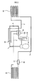
- FIG. 3 is a view schematically showing the structure of a heat pump according to a second preferred embodiment of the present invention
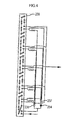
- FIG. 4 is a view schematically showing distributors connected to an outdoor heat exchanger in the heat pump according to the second preferred embodiment of the present invention.
- the four-way valve 222 is connected to the outlet of the compressor 221 via a first connection pipe 223, on which a high-pressure switch 226 is mounted.
- the high-pressure switch 226 is operated by a pressure sensor.
- the four-way valve 222 is also connected to the indoor heat exchanger 227 via a second connection pipe 228.
- the indoor heat exchanger 227 is connected to the outdoor heat exchanger 239 via a third connection pipe 229.
- connection pipe 229 On the third connection pipe 229 are mounted the first heating-operation distributor 236 and a first check valve 230 for preventing back flow of refrigerant to the indoor heat exchanger 227.
- the first heating-operation distributor 236 and the first check valve 230 are connected to each other in serial.
- On the third connection pipe 229 are also mounted the first expansion valve 231 and the first cooling-operation distributor 232 having a strainer.
- the first expansion valve 231 and the first cooling-operation distributor 232 are connected to each other in serial.
- the first expansion valve 231 and the first cooling-operation distributor 232 are connected to the first heating-operation distributor 236 and the first check valve 230 in parallel on the third connection pipe 229 for controlling the flow of refrigerant.
- connection pipe 229 On the third connection pipe 229 are also mounted a second check valve 234 for preventing back flow of refrigerant to the outdoor heat exchanger 239 and the second cooling-operation distributor 237.
- the second check valve 234 and the second cooling-operation distributor 237 are connected to each other in serial.
- second heating-operation distributor 238 On the third connection pipe 229 are also mounted the second heating-operation distributor 238 having a strainer and the second expansion valve 235.
- the second heating-operation distributor 238 and the second expansion valve 235 are connected to each other in serial.
- the second heating-operation distributor 238 and the second expansion valve 235 are connected to the second check valve 234 and the second cooling-operation distributor 237 in parallel on the third connection pipe 229 for controlling the flow of refrigerant.
- the four-way valve 222 is connected to the outdoor heat exchanger 239 via a fourth connection pipe 240.
- the four-way valve 222 is also connected to the inlet of the compressor 221 via a fifth connection pipe 245, on which a low-pressure switch 243 and the accumulator 244 are mounted.
- the low-pressure switch 243 is operated by a pressure sensor. Refrigerant is circulated in the heat pump through the five above-mentioned connection pipes.
- Adjacent to the indoor heat exchanger 227 is disposed an indoor fan 258 for blowing air to the indoor heat exchanger 227.
- Adjacent to the outdoor heat exchanger 239 is disposed an outdoor fan 259 for blowing air to the outdoor heat exchanger 239.
- the third connection pipe 229 and the accumulator 244 selectively communicate with each other through the bypass pipe 260, on which a bypass valve 261 is mounted.
- a bypass valve 261 When the temperature of outdoor air is low or the load is excessive, some of the refrigerant introduced into the compressor 221 through the outdoor heat exchanger 239 is circulated through the bypass pipe 260. As a result, the pressure of the compressor 221 is stabilized.
- each of the distributors 232, 236, 237 and 238 has a plurality of branch pipes, which are connected to the refrigerant pipe of the outdoor heat exchanger 239 such that the outdoor heat exchanger 239 optimally performs heat exchange.
- the heat exchange efficiency is considerably improved.
- the evaporation process is smoothly performed especially when the temperature of outdoor air is less than 15 degrees Celsius below zero as in winter, and therefore, the outdoor heat exchanger 239 is prevented from being covered with frost.
- the compressor 221 When a user powers the heat pump on and selects cooling operation mode in summer, the compressor 221 is operated, based on a control signal from a controller (not shown), to compress low-temperature and low-pressure gas refrigerant into high-temperature and high-pressure gas refrigerant.
- the high-temperature and high-pressure gas refrigerant is supplied to the four-way valve 222 through the first connection pipe 223.
- the high-temperature and high-pressure gas refrigerant flows from the four-way valve 222 to the outdoor heat exchanger 239 through the fourth connection pipe 240.
- the high-temperature and high-pressure gas refrigerant is condensed by the outdoor heat exchanger 239.
- the high-temperature and high-pressure gas refrigerant is changed into high-temperature and high-pressure liquid refrigerant, and heat emitted from the refrigerant is discharged to the outside by the outdoor fan 259.
- the high-temperature and high-pressure liquid refrigerant having passed through the outdoor heat exchanger 239 flows through the second cooling-operation distributor 237 and the second check valve 234 mounted on the third connection pipe 229, and then flows through the first cooling-operation distributor 232 and the first expansion valve 231.
- the high-temperature and high-pressure liquid refrigerant is expanded while passing through the first expansion valve 231 with the result that the temperature and the pressure of the refrigerant is sharply decreased.
- the low-temperature and low-pressure liquid refrigerant having passed through the first expansion valve 231 absorbs heat surrounding the refrigerant while the low-temperature and low-pressure liquid refrigerant is changed into gas refrigerant by the indoor heat exchanger 227. At this time, air whose heat is absorbed by the refrigerant is blown into the interior of a room where the indoor heat exchanger 227 is installed by the indoor fan 258. In this way, the cooling operation of the heat pump is accomplished.
- the low-temperature and low-pressure refrigerant having passed through the indoor heat exchanger 227 flows to the four-way valve 222 through the second connection pipe 228, and is then introduced into the accumulator 244 mounted on the fifth connection pipe 245.
- the refrigerant is separated into gas refrigerant and liquid refrigerant, and the gas refrigerant introduced into the compressor 221 where the gas refrigerant is compressed into high-temperature and high-pressure gas refrigerant.
- the heat pump While the cooling operation of the heat pump is performed as mentioned above, the heat pump is not affected by the difference between the temperature of outdoor air and the interior temperature of the room where the indoor heat exchanger 227 is installed. Consequently, normal cooling operation of the heat pump is possible without the excessive operation of the heat pump.
- the compressor 221 When the user selects heating operation mode in winter, the compressor 221 is operated, based on a control signal from the controller, to compress low-temperature and low-pressure gas refrigerant into a high-temperature and high-pressure gas refrigerant.
- the high-temperature and high-pressure gas refrigerant is supplied to the four-way valve 222 through the first connection pipe 223.
- the high-temperature and high-pressure gas refrigerant flows from the four-way valve 222 to the indoor heat exchanger 227 through the second connection pipe 228.
- the high-temperature and high-pressure gas refrigerant is condensed by the indoor heat exchanger 227 with the result that heat is emitted from the refrigerant.
- air is blown to the indoor heat exchanger 227 by the indoor fan 258, and therefore, the heat generated in the indoor heat exchanger 227 is transferred to the air blown to the indoor heat exchanger 227.
- the temperature of the interior of the room where the indoor heat exchanger 227 is installed is increased. In this way, the heating operation of the heat pump is accomplished.
- the high-temperature and high-pressure refrigerant having passed through the indoor heat exchanger 227 flows to the outdoor heat exchanger 239 through the third connection pipe 229.
- the refrigerant flowing to the outdoor heat exchanger 239 passes through the first heating-operation distributor 236 and the first check valve 230 for preventing back flow of refrigerant to the indoor heat exchanger 227, and then through the second heating-operation distributor 238 having the strainer and the second expansion valve 235.
- the refrigerant passes through the second expansion valve 235, the refrigerant is expanded into low-temperature and low-pressure liquid refrigerant.
- the low-temperature and low-pressure liquid refrigerant is supplied to the outdoor heat exchanger 239, by which the low-temperature and low-pressure liquid refrigerant is changed into low-temperature and low-pressure gas refrigerant.
- the low-temperature and low-pressure gas refrigerant is introduced into the accumulator 244 and the compressor 221 through the fourth connection pipe 240, the four-way valve 222 and the fifth connection pipe 245. In this way, the refrigerant is continuously circulated, and therefore, the heating operation of the heat pump is continuously performed.
- the bypass valve 261 is opened such that, when the liquid refrigerant having passed through the first heating-operation distributor 236 and the first check valve 230 flows through the third connection pipe 229, some of the liquid refrigerant having passed through the first heating-operation distributor 236 and the first check valve 230 flows to the accumulator 244 through the bypass valve 261.
- the amount of the liquid refrigerant introduced into the outdoor heat exchanger 239 is decreased, and therefore, the heat exchange operation is sufficiently carried out by the outdoor heat exchanger 239. Consequently, the compressor 221 is prevented from being frozen in winter, and the high pressure of the outdoor heat exchanger 239 is reduced.
- the temperature and the pressure of the liquid refrigerant flowing through the bypass valve 260 are decreased by the third expansion valve 249, and therefore, the low-temperature and low-pressure liquid refrigerant is introduced into the accumulator 244 where the low-temperature and low-pressure liquid refrigerant is slowly evaporated by the temperature of the gas refrigerant evaporated by the outdoor heat exchanger 239. As a result, gas refrigerant is introduced into the compressor 221.
- FIG. 5 is a view schematically showing a compressor discharge pressure controlling apparatus according to a third preferred embodiment of the present invention mounted in a heat pump
- FIG. 6 is a view schematically showing the interior structure of the compressor discharge pressure controlling apparatus according to the third preferred embodiment of the present invention.
- the compressor discharge pressure controlling apparatus comprises a bypass pipe 310 and an opening/closing device 320.
- the bypass pipe 310 branches off from a refrigerant pipe through which refrigerant discharged from a compressor 301 flows, and is connected to a refrigerant pipe connected between an indoor heat exchanger 302 and an expansion valve 303.
- the opening/closing device 320 is mounted on the bypass pipe 310 for opening the bypass pipe 310, when discharged pressure from the compressor 301 is excessive, to guide some of gas refrigerant introduced into an outdoor heat exchanger 304 to the indoor heat exchanger 302.
- the opening/closing device 320 comprises: a device body 321 having an inlet port 321a and an outlet port 321b; a discharge pressure adjusting plate 323 disposed in the device body 321 for opening or closing the outlet port 321b by the pressure of the gas refrigerant introduced into the device body 321 through the inlet port 321a; and a spring 322, having one end attached to the inside of the device body 321 and the other end attached to the discharge pressure adjusting plate 323, for elastically supporting the discharge pressure adjusting plate 323 toward the inlet port 321a.
- an auxiliary expansion valve 330 is mounted on the refrigerant pipe, which is connected to the outlet port 321b, for expanding high-temperature and high-pressure gas refrigerant into low-temperature and low-pressure gas refrigerant by throttling expansion action.
- the low-temperature and low-pressure gas refrigerant expanded by the auxiliary expansion valve 330 is introduced into the indoor heat exchanger 302.
- gas refrigerant is changed into liquid refrigerant, and then the liquid refrigerant is changed into the gas refrigerant.
- a switching operation between the heating operation mode and cooling operation mode is performed by the four-way valve in the heat pump.
- the compressor 301 mounted in the heat pump serves to compress gas refrigerant into high-temperature and high-pressure gas refrigerant.
- the discharge pressure from the compressor 301 is excessively increased, and therefore, the compressor 301 may be damaged.
- the discharge pressure adjusting plate 323 is moved away from the inlet port 321a against the elastic force of the spring 322, and therefore, the inlet port 321a communicates with the outlet port 321b.
- the gas refrigerant discharged from the compressor 301 flows through the bypass pipe 310.
- the gas refrigerant flowing through the bypass pipe 310 passes through the auxiliary expansion valve 330.
- the high-temperature and high-pressure gas refrigerant is expanded into low-temperature and low-pressure gas refrigerant by throttling expansion action.
- the low-temperature and low-pressure gas refrigerant expanded by the auxiliary expansion valve 330 is introduced into the indoor heat exchanger 302.
- the pressure and the temperature of the refrigerant discharged from the compressor 301 are decreased, and therefore, the pressure and the temperature of the refrigerant introduced into the compressor 301 are increased.
- the compressor 301 As the pressure and the temperature of the refrigerant discharged from the compressor 301 are decreased, the compressor 301 is prevented from being damaged, and the pressure and the temperature of the refrigerant introduced into the compressor 301 are increased.
- the heat pump is normally operated when the temperature of outdoor air is low, and the low-temperature and low-pressure liquid refrigerant discharged from the outdoor heat exchanger is prevented from entering into the accumulator and the compressor. Consequently, the present invention has the effect of preventing the compressor from being damaged.
- the compressor discharge pressure is maintained to a predetermined stable pressure level when the temperature of outdoor air is low or if the load is excessive. Consequently, the present invention has the effect of stabilizing the compressor suction pressure.
- the present invention has the effect of preventing the compressor from being damaged.
- the present invention has the effect of uniformly maintaining the compressor discharge pressure and the compressor suction pressure.
Landscapes
- Engineering & Computer Science (AREA)
- Physics & Mathematics (AREA)
- Mechanical Engineering (AREA)
- Thermal Sciences (AREA)
- General Engineering & Computer Science (AREA)
- Compression-Type Refrigeration Machines With Reversible Cycles (AREA)
Abstract
Description
Claims (7)
- A heat pump comprising:a compressor (10);indoor (20) and outdoor (40) heat exchangers for condensing or evaporating refrigerant compressed by the compressor (10) according to cooling or heating operation mode;a four-way valve (60) for guiding the flow of the compressed refrigerant to the indoor heat exchanger (20) or the outdoor heat exchanger (40) according to the cooling or heating operation mode;an expansion valve (30) for selectively decreasing the pressure of liquid refrigerant according to the cooling or heating operation mode;a check valve (31) selectively opened or closed according to the cooling or heating operation mode for guiding the flow of the liquid refrigerant to the expansion valve (30);an accumulator (50) for preventing the liquid refrigerant from entering into the inlet of the compressor (10);a plurality of connection pipes (1,2,3) for connecting the compressor (10), the indoor (20) and outdoor (40) heat exchangers, the four-way valve (60), the expansion valve (30), the check valve (31), and the accumulator (50) to one another such that the compressor (10), the indoor (20) and outdoor (40) heat exchangers, the four-way valve (60), the expansion valve (30), the check valve (31), and the accumulator (50) communicate with one another; anda heat exchange part (110) for performing heat exchange between the connection pipe connected to the inlet of the accumulator (50) and the connection pipe connected to the indoor heat exchanger (20).
- The heat pump as set forth in claim 1, wherein the connection pipe (5) extending through the heat exchange part (110) is provided at the outer circumferential part thereof with a plurality of heat-sink pins (5a).
- A heat pump comprising:a compressor (221);indoor (227) and outdoor (239) heat exchangers for condensing or evaporating refrigerant compressed by the compressor (221) according to cooling or heating operation mode;a four-way valve (222) for guiding the flow of the compressed refrigerant to the indoor heat exchanger (227) or the outdoor heat exchanger (239) according to the cooling or heating operation mode;first and second expansion valves (231, 235) mounted at the indoor (227) and outdoor (239) heat exchangers, respectively, for selectively decreasing the pressure of the liquid refrigerant according to the cooling or heating operation mode;first (230) and second (234) check valves selectively opened or closed according to the cooling or heating operation mode for guiding the flow of the liquid refrigerant to the first and second expansion valves (230, 234), respectively;an accumulator (244) for preventing the liquid refrigerant from entering into the inlet of the compressor; anda plurality of connection pipes (223, 228, 229, 240, 245) for connecting the compressor (221), the indoor and outdoor heat exchangers (227, 239), the four-way valve (222), the first and second expansion valves (231, 235), the first and second check valves (230, 234), and the accumulator (244) to one another such that the compressor (221), the indoor and outdoor heat exchangers (227, 239), the four-way valve (222), the first and second expansion valves (231, 235), the first and second check valves (230, 234), and the accumulator (244) communicate with one another, wherein the heat pump further comprises:a bypass pipe (260), having a bypass valve (261) mounted thereon, connected between the connection pipe connecting the indoor and outdoor heat exchangers (227, 239) and the accumulator (244) for guiding some of the refrigerant introduced into the outdoor heat exchanger (239) to the accumulator (244) therethrough when the evaporation function of the outdoor heat exchanger (239) is lowered or excessive load is applied to the compressor (244) during a heating operation of the heat pump.
- The heat pump as set forth in claim 3, further comprising:a plurality of distributors (232, 236, 237, 238) connected to the first and second expansion valves (231, 235) and the first and second check valves (230, 234), respectively, wherein each of the distributors (232, 236, 237, 238) has a plurality of branch pipes, which are connected to the corresponding indoor or outdoor heat exchanger (227, 239) such that the indoor (227) or outdoor (239) heat exchanger effectively performs a condensing or evaporating function according to the cooling or heating operation mode.
- A compressor discharge pressure control apparatus for a heat pump, the heat pump comprising: a compressor (301); indoor and outdoor heat exchangers (302, 304); a four-way valve; and an expansion valve (303), wherein the apparatus comprises:a bypass pipe (310) branching off from a refrigerant pipe through which refrigerant discharged from the compressor (301) flows, the bypass pipe (310) being connected to a refrigerant pipe connected between the expansion valve (303) and the indoor heat exchanger (302); andan opening/closing device (320) mounted on the bypass pipe (310) for opening the bypass pipe (310), when discharged pressure from the compressor (301) is excessive, to guide some of gas refrigerant introduced into the outdoor heat exchanger (304) to the indoor heat exchanger (302).
- The apparatus as set forth in claim 5, wherein the opening/closing device (320) comprises:a device body (321) having an inlet port (321a) and an outlet port (321b);a discharge pressure adjusting plate (323) disposed in the device body (321) for opening or closing the outlet port (321b) by the pressure of the gas refrigerant introduced into the device body (321) through the inlet port (321a); anda spring (322), having one end attached to the inside of the device body (321) and the other end attached to the discharge pressure adjusting plate, for elastically supporting the discharge pressure adjusting plate (323) toward the inlet port (321a).
- The apparatus as set forth in claim 5, further comprising:an auxiliary expansion valve (330) mounted on the refrigerant pipe, which is connected to the outlet port (321b) of the opening/closing device (320), for expanding high-temperature and high-pressure gas refrigerant into low-temperature and low-pressure gas refrigerant by throttling expansion action such that the low-temperature and low-pressure gas refrigerant is introduced into the indoor heat exchanger (302).
Applications Claiming Priority (6)
| Application Number | Priority Date | Filing Date | Title |
|---|---|---|---|
| KR2004027886 | 2004-04-22 | ||
| KR1020040027886A KR100554566B1 (en) | 2004-04-22 | 2004-04-22 | Cryogenic Heat Pump Cycles |
| KR1020040027883A KR20050102479A (en) | 2004-04-22 | 2004-04-22 | Structure for improving superheat degree of refrigerant in heatpump |
| KR2004027883 | 2004-04-22 | ||
| KR2004088480 | 2004-11-02 | ||
| KR1020040088480A KR100661143B1 (en) | 2004-11-02 | 2004-11-02 | Compressor discharge pressure control device of heat pump |
Publications (2)
| Publication Number | Publication Date |
|---|---|
| EP1589299A2 true EP1589299A2 (en) | 2005-10-26 |
| EP1589299A3 EP1589299A3 (en) | 2007-11-21 |
Family
ID=34935550
Family Applications (1)
| Application Number | Title | Priority Date | Filing Date |
|---|---|---|---|
| EP05008786A Withdrawn EP1589299A3 (en) | 2004-04-22 | 2005-04-21 | Heat pump and compressor discharge pressure controlling apparatus for the same |
Country Status (2)
| Country | Link |
|---|---|
| US (1) | US7353664B2 (en) |
| EP (1) | EP1589299A3 (en) |
Cited By (4)
| Publication number | Priority date | Publication date | Assignee | Title |
|---|---|---|---|---|
| WO2011109455A1 (en) * | 2010-03-03 | 2011-09-09 | Parker Hannifin Corporation | Condenser bypass for two-phase electronics cooling system |
| EP2733440A1 (en) * | 2012-11-19 | 2014-05-21 | LG Electronics, Inc. | Air conditioner and control method thereof |
| EP2623873A3 (en) * | 2012-02-03 | 2017-09-13 | LG Electronics, Inc. | Outdoor heat exchanger and air conditioner comprising the same |
| CN107421156A (en) * | 2017-09-18 | 2017-12-01 | 东莞市正旭新能源设备科技有限公司 | A kind of tobacco roasting heat pump with cold recovery function |
Families Citing this family (6)
| Publication number | Priority date | Publication date | Assignee | Title |
|---|---|---|---|---|
| US20070056311A1 (en) * | 2005-09-14 | 2007-03-15 | Kaori Heat Treatment Co., Ltd. | Heating and cooling apparatus |
| US20110088869A1 (en) * | 2009-10-13 | 2011-04-21 | Carrier Corporation | Heat treating a dairy product using a heat pump |
| US20130104574A1 (en) * | 2011-11-02 | 2013-05-02 | Daniel J. Dempsey | Hybrid Space And Hot Water Heating Heat Pump |
| US10184688B2 (en) | 2011-12-28 | 2019-01-22 | Desert Aire Corp. | Air conditioning apparatus for efficient supply air temperature control |
| KR101852374B1 (en) * | 2012-01-20 | 2018-04-26 | 엘지전자 주식회사 | Outdoor heat exchanger |
| EP3779326B1 (en) * | 2018-04-11 | 2023-11-29 | Mitsubishi Electric Corporation | Refrigeration cycle device |
Family Cites Families (23)
| Publication number | Priority date | Publication date | Assignee | Title |
|---|---|---|---|---|
| US3423954A (en) * | 1967-11-13 | 1969-01-28 | Westinghouse Electric Corp | Refrigeration systems with accumulator means |
| US4030315A (en) * | 1975-09-02 | 1977-06-21 | Borg-Warner Corporation | Reverse cycle heat pump |
| DE2709343C2 (en) * | 1976-03-05 | 1983-07-28 | Hitachi, Ltd., Tokyo | Heat pump system |
| US4238932A (en) * | 1979-07-23 | 1980-12-16 | General Electric Company | High pressure charge storage system |
| DE3139460C1 (en) * | 1981-10-03 | 1983-06-01 | Danfoss A/S, 6430 Nordborg | Cold or heat pump installation |
| JPH0686969B2 (en) | 1984-12-07 | 1994-11-02 | 株式会社日立製作所 | Air-cooled heat pump type refrigeration cycle |
| JPH02287062A (en) * | 1989-04-26 | 1990-11-27 | Hitachi Ltd | Air conditioner |
| JPH0464870A (en) * | 1990-07-02 | 1992-02-28 | Toshiba Corp | Air-conditioning machine |
| JP3009481B2 (en) * | 1990-12-26 | 2000-02-14 | 三菱重工業株式会社 | Heat pump type air conditioner |
| KR930002204B1 (en) | 1990-12-31 | 1993-03-27 | 삼성전자 주식회사 | Satellite broadcasting receiver built in tv |
| FR2704939B1 (en) * | 1993-05-06 | 1995-06-23 | Valeo Thermique Habitacle | Refrigerant circuit with improved efficiency. |
| JP3303443B2 (en) * | 1993-07-02 | 2002-07-22 | 株式会社デンソー | Air conditioner |
| US5479789A (en) * | 1994-12-29 | 1996-01-02 | Aire Solutions, Inc. | Heat exchanger for a heat pump |
| JP3692630B2 (en) * | 1995-10-24 | 2005-09-07 | ダイキン工業株式会社 | Heat transfer device |
| EP0800940A3 (en) * | 1996-04-10 | 2001-06-06 | Denso Corporation | Vehicular air conditioning system for electric vehicles |
| JPH1114177A (en) * | 1997-06-26 | 1999-01-22 | Mitsubishi Heavy Ind Ltd | Air conditioner |
| KR100248719B1 (en) | 1997-11-04 | 2000-04-01 | 구자홍 | Cooling cycle and heating cycle |
| JP3888403B2 (en) | 1997-12-18 | 2007-03-07 | 株式会社富士通ゼネラル | Method and apparatus for controlling air conditioner |
| KR100332778B1 (en) | 1999-09-22 | 2002-04-17 | 구자홍 | Flow control device for heat pump |
| KR20030043038A (en) * | 2001-11-26 | 2003-06-02 | 주식회사 엘지이아이 | Refrigerating cycle and control method |
| JP2003240362A (en) | 2002-02-20 | 2003-08-27 | Fujitsu General Ltd | Air conditioner |
| US6763673B2 (en) * | 2002-08-22 | 2004-07-20 | Parker-Hannifan Corporation | Remote distributor with integrated check valve |
| JP4321095B2 (en) * | 2003-04-09 | 2009-08-26 | 日立アプライアンス株式会社 | Refrigeration cycle equipment |
-
2005
- 2005-04-21 EP EP05008786A patent/EP1589299A3/en not_active Withdrawn
- 2005-04-21 US US11/111,035 patent/US7353664B2/en not_active Expired - Fee Related
Cited By (4)
| Publication number | Priority date | Publication date | Assignee | Title |
|---|---|---|---|---|
| WO2011109455A1 (en) * | 2010-03-03 | 2011-09-09 | Parker Hannifin Corporation | Condenser bypass for two-phase electronics cooling system |
| EP2623873A3 (en) * | 2012-02-03 | 2017-09-13 | LG Electronics, Inc. | Outdoor heat exchanger and air conditioner comprising the same |
| EP2733440A1 (en) * | 2012-11-19 | 2014-05-21 | LG Electronics, Inc. | Air conditioner and control method thereof |
| CN107421156A (en) * | 2017-09-18 | 2017-12-01 | 东莞市正旭新能源设备科技有限公司 | A kind of tobacco roasting heat pump with cold recovery function |
Also Published As
| Publication number | Publication date |
|---|---|
| US7353664B2 (en) | 2008-04-08 |
| US20050235675A1 (en) | 2005-10-27 |
| EP1589299A3 (en) | 2007-11-21 |
Similar Documents
| Publication | Publication Date | Title |
|---|---|---|
| KR101155496B1 (en) | Heat pump type speed heating apparatus | |
| US11629891B2 (en) | Heat pump system | |
| JP2003075009A (en) | Heat pump system | |
| JP2002168532A (en) | Supercritical steam compression system, and device for regulating pressure in high-pressure components of refrigerant circulating therein | |
| WO2006013834A1 (en) | Freezing apparatus | |
| KR101737365B1 (en) | Air conditioner | |
| KR101161381B1 (en) | Refrigerant cycle apparatus | |
| JP2015068564A (en) | Heat pump system and heat pump type water heater | |
| US6843425B2 (en) | Air conditioner and method for controlling the same | |
| US7353664B2 (en) | Heat pump and compressor discharge pressure controlling apparatus for the same | |
| WO2007102345A1 (en) | Refrigeration device | |
| KR200274119Y1 (en) | Heat pump system | |
| JP4084915B2 (en) | Refrigeration system | |
| WO2009096179A1 (en) | Auxiliary unit for heating and air conditioner | |
| CN100552327C (en) | Heat pump and compressor discharge pressure control device for heat pump | |
| US20220252317A1 (en) | A heat pump | |
| KR102777197B1 (en) | Compressor refrigerant bypass circulation method in winter refrigerant cycle | |
| KR100588846B1 (en) | Heat Pump Air Conditioner | |
| CN114508874B (en) | Compressor cooling system, cooling method and air conditioner | |
| KR100473712B1 (en) | Refrigeration cycle | |
| KR200362724Y1 (en) | Refrigerant cycle system | |
| KR200304217Y1 (en) | Heat pump type air conditioning apparatus with a medium heat exchanger | |
| KR200362723Y1 (en) | Refrigerant cycle system | |
| KR200362728Y1 (en) | Refrigerant cycle system | |
| KR200362725Y1 (en) | Refrigerant cycle system |
Legal Events
| Date | Code | Title | Description |
|---|---|---|---|
| PUAI | Public reference made under article 153(3) epc to a published international application that has entered the european phase |
Free format text: ORIGINAL CODE: 0009012 |
|
| AK | Designated contracting states |
Kind code of ref document: A2 Designated state(s): AT BE BG CH CY CZ DE DK EE ES FI FR GB GR HU IE IS IT LI LT LU MC NL PL PT RO SE SI SK TR |
|
| AX | Request for extension of the european patent |
Extension state: AL BA HR LV MK YU |
|
| PUAL | Search report despatched |
Free format text: ORIGINAL CODE: 0009013 |
|
| AK | Designated contracting states |
Kind code of ref document: A3 Designated state(s): AT BE BG CH CY CZ DE DK EE ES FI FR GB GR HU IE IS IT LI LT LU MC NL PL PT RO SE SI SK TR |
|
| AX | Request for extension of the european patent |
Extension state: AL BA HR LV MK YU |
|
| 17P | Request for examination filed |
Effective date: 20080311 |
|
| AKX | Designation fees paid |
Designated state(s): AT BE BG CH CY CZ DE DK EE ES FI FR GB GR HU IE IS IT LI LT LU MC NL PL PT RO SE SI SK TR |
|
| STAA | Information on the status of an ep patent application or granted ep patent |
Free format text: STATUS: THE APPLICATION HAS BEEN WITHDRAWN |
|
| 18W | Application withdrawn |
Effective date: 20091027 |