EP1589280B1 - Gaserhitzer, Gaszuführvorrichtung und Verfahren - Google Patents
Gaserhitzer, Gaszuführvorrichtung und Verfahren Download PDFInfo
- Publication number
- EP1589280B1 EP1589280B1 EP04252324.1A EP04252324A EP1589280B1 EP 1589280 B1 EP1589280 B1 EP 1589280B1 EP 04252324 A EP04252324 A EP 04252324A EP 1589280 B1 EP1589280 B1 EP 1589280B1
- Authority
- EP
- European Patent Office
- Prior art keywords
- gas
- heater
- heat
- jacket
- heat exchanger
- Prior art date
- Legal status (The legal status is an assumption and is not a legal conclusion. Google has not performed a legal analysis and makes no representation as to the accuracy of the status listed.)
- Expired - Lifetime
Links
- 238000000034 method Methods 0.000 title claims description 6
- 239000011148 porous material Substances 0.000 claims description 23
- 239000000463 material Substances 0.000 claims description 8
- 239000004020 conductor Substances 0.000 claims description 7
- 229910052751 metal Inorganic materials 0.000 claims description 6
- 239000002184 metal Substances 0.000 claims description 5
- 229910001369 Brass Inorganic materials 0.000 claims description 4
- 229910000906 Bronze Inorganic materials 0.000 claims description 4
- RYGMFSIKBFXOCR-UHFFFAOYSA-N Copper Chemical compound [Cu] RYGMFSIKBFXOCR-UHFFFAOYSA-N 0.000 claims description 4
- CWYNVVGOOAEACU-UHFFFAOYSA-N Fe2+ Chemical compound [Fe+2] CWYNVVGOOAEACU-UHFFFAOYSA-N 0.000 claims description 4
- 229910000831 Steel Inorganic materials 0.000 claims description 4
- 229910045601 alloy Inorganic materials 0.000 claims description 4
- 239000000956 alloy Substances 0.000 claims description 4
- 239000004411 aluminium Substances 0.000 claims description 4
- 229910052782 aluminium Inorganic materials 0.000 claims description 4
- XAGFODPZIPBFFR-UHFFFAOYSA-N aluminium Chemical compound [Al] XAGFODPZIPBFFR-UHFFFAOYSA-N 0.000 claims description 4
- 239000010951 brass Substances 0.000 claims description 4
- 239000010974 bronze Substances 0.000 claims description 4
- 239000010949 copper Substances 0.000 claims description 4
- 229910052802 copper Inorganic materials 0.000 claims description 4
- KUNSUQLRTQLHQQ-UHFFFAOYSA-N copper tin Chemical compound [Cu].[Sn] KUNSUQLRTQLHQQ-UHFFFAOYSA-N 0.000 claims description 4
- -1 ferrous metals Chemical class 0.000 claims description 4
- 239000010935 stainless steel Substances 0.000 claims description 4
- 229910001220 stainless steel Inorganic materials 0.000 claims description 4
- 239000010959 steel Substances 0.000 claims description 4
- 239000002131 composite material Substances 0.000 claims description 2
- 238000005245 sintering Methods 0.000 claims 1
- 239000007789 gas Substances 0.000 description 152
- 238000010438 heat treatment Methods 0.000 description 12
- 230000000694 effects Effects 0.000 description 5
- 239000002245 particle Substances 0.000 description 4
- XKRFYHLGVUSROY-UHFFFAOYSA-N Argon Chemical compound [Ar] XKRFYHLGVUSROY-UHFFFAOYSA-N 0.000 description 2
- 238000012986 modification Methods 0.000 description 2
- 230000004048 modification Effects 0.000 description 2
- 230000009467 reduction Effects 0.000 description 2
- 239000007787 solid Substances 0.000 description 2
- OKTJSMMVPCPJKN-UHFFFAOYSA-N Carbon Chemical compound [C] OKTJSMMVPCPJKN-UHFFFAOYSA-N 0.000 description 1
- 241000410537 Epipleoneura lamina Species 0.000 description 1
- 239000004760 aramid Substances 0.000 description 1
- 229910052786 argon Inorganic materials 0.000 description 1
- 229920003235 aromatic polyamide Polymers 0.000 description 1
- 230000000903 blocking effect Effects 0.000 description 1
- 229910052799 carbon Inorganic materials 0.000 description 1
- 230000003197 catalytic effect Effects 0.000 description 1
- 230000008859 change Effects 0.000 description 1
- 238000001816 cooling Methods 0.000 description 1
- 239000000835 fiber Substances 0.000 description 1
- 239000011521 glass Substances 0.000 description 1
- 230000006872 improvement Effects 0.000 description 1
- 239000007788 liquid Substances 0.000 description 1
- 230000013011 mating Effects 0.000 description 1
- 239000011159 matrix material Substances 0.000 description 1
- 230000010355 oscillation Effects 0.000 description 1
- 230000005855 radiation Effects 0.000 description 1
- 230000001105 regulatory effect Effects 0.000 description 1
Images





Classifications
-
- F—MECHANICAL ENGINEERING; LIGHTING; HEATING; WEAPONS; BLASTING
- F17—STORING OR DISTRIBUTING GASES OR LIQUIDS
- F17C—VESSELS FOR CONTAINING OR STORING COMPRESSED, LIQUEFIED OR SOLIDIFIED GASES; FIXED-CAPACITY GAS-HOLDERS; FILLING VESSELS WITH, OR DISCHARGING FROM VESSELS, COMPRESSED, LIQUEFIED, OR SOLIDIFIED GASES
- F17C7/00—Methods or apparatus for discharging liquefied, solidified, or compressed gases from pressure vessels, not covered by another subclass
- F17C7/02—Discharging liquefied gases
-
- F—MECHANICAL ENGINEERING; LIGHTING; HEATING; WEAPONS; BLASTING
- F16—ENGINEERING ELEMENTS AND UNITS; GENERAL MEASURES FOR PRODUCING AND MAINTAINING EFFECTIVE FUNCTIONING OF MACHINES OR INSTALLATIONS; THERMAL INSULATION IN GENERAL
- F16L—PIPES; JOINTS OR FITTINGS FOR PIPES; SUPPORTS FOR PIPES, CABLES OR PROTECTIVE TUBING; MEANS FOR THERMAL INSULATION IN GENERAL
- F16L53/00—Heating of pipes or pipe systems; Cooling of pipes or pipe systems
- F16L53/30—Heating of pipes or pipe systems
- F16L53/35—Ohmic-resistance heating
- F16L53/38—Ohmic-resistance heating using elongate electric heating elements, e.g. wires or ribbons
-
- F—MECHANICAL ENGINEERING; LIGHTING; HEATING; WEAPONS; BLASTING
- F28—HEAT EXCHANGE IN GENERAL
- F28D—HEAT-EXCHANGE APPARATUS, NOT PROVIDED FOR IN ANOTHER SUBCLASS, IN WHICH THE HEAT-EXCHANGE MEDIA DO NOT COME INTO DIRECT CONTACT
- F28D7/00—Heat-exchange apparatus having stationary tubular conduit assemblies for both heat-exchange media, the media being in contact with different sides of a conduit wall
- F28D7/02—Heat-exchange apparatus having stationary tubular conduit assemblies for both heat-exchange media, the media being in contact with different sides of a conduit wall the conduits being helically coiled
- F28D7/026—Heat-exchange apparatus having stationary tubular conduit assemblies for both heat-exchange media, the media being in contact with different sides of a conduit wall the conduits being helically coiled the conduits of only one medium being helically coiled and formed by bent members, e.g. plates, the coils having a cylindrical configuration
-
- F—MECHANICAL ENGINEERING; LIGHTING; HEATING; WEAPONS; BLASTING
- F28—HEAT EXCHANGE IN GENERAL
- F28F—DETAILS OF HEAT-EXCHANGE AND HEAT-TRANSFER APPARATUS, OF GENERAL APPLICATION
- F28F13/00—Arrangements for modifying heat-transfer, e.g. increasing, decreasing
- F28F13/003—Arrangements for modifying heat-transfer, e.g. increasing, decreasing by using permeable mass, perforated or porous materials
-
- F—MECHANICAL ENGINEERING; LIGHTING; HEATING; WEAPONS; BLASTING
- F17—STORING OR DISTRIBUTING GASES OR LIQUIDS
- F17C—VESSELS FOR CONTAINING OR STORING COMPRESSED, LIQUEFIED OR SOLIDIFIED GASES; FIXED-CAPACITY GAS-HOLDERS; FILLING VESSELS WITH, OR DISCHARGING FROM VESSELS, COMPRESSED, LIQUEFIED, OR SOLIDIFIED GASES
- F17C2203/00—Vessel construction, in particular walls or details thereof
- F17C2203/06—Materials for walls or layers thereof; Properties or structures of walls or their materials
- F17C2203/0634—Materials for walls or layers thereof
- F17C2203/0636—Metals
-
- F—MECHANICAL ENGINEERING; LIGHTING; HEATING; WEAPONS; BLASTING
- F17—STORING OR DISTRIBUTING GASES OR LIQUIDS
- F17C—VESSELS FOR CONTAINING OR STORING COMPRESSED, LIQUEFIED OR SOLIDIFIED GASES; FIXED-CAPACITY GAS-HOLDERS; FILLING VESSELS WITH, OR DISCHARGING FROM VESSELS, COMPRESSED, LIQUEFIED, OR SOLIDIFIED GASES
- F17C2203/00—Vessel construction, in particular walls or details thereof
- F17C2203/06—Materials for walls or layers thereof; Properties or structures of walls or their materials
- F17C2203/0634—Materials for walls or layers thereof
- F17C2203/0636—Metals
- F17C2203/0639—Steels
-
- F—MECHANICAL ENGINEERING; LIGHTING; HEATING; WEAPONS; BLASTING
- F17—STORING OR DISTRIBUTING GASES OR LIQUIDS
- F17C—VESSELS FOR CONTAINING OR STORING COMPRESSED, LIQUEFIED OR SOLIDIFIED GASES; FIXED-CAPACITY GAS-HOLDERS; FILLING VESSELS WITH, OR DISCHARGING FROM VESSELS, COMPRESSED, LIQUEFIED, OR SOLIDIFIED GASES
- F17C2203/00—Vessel construction, in particular walls or details thereof
- F17C2203/06—Materials for walls or layers thereof; Properties or structures of walls or their materials
- F17C2203/0634—Materials for walls or layers thereof
- F17C2203/0636—Metals
- F17C2203/0639—Steels
- F17C2203/0643—Stainless steels
-
- F—MECHANICAL ENGINEERING; LIGHTING; HEATING; WEAPONS; BLASTING
- F17—STORING OR DISTRIBUTING GASES OR LIQUIDS
- F17C—VESSELS FOR CONTAINING OR STORING COMPRESSED, LIQUEFIED OR SOLIDIFIED GASES; FIXED-CAPACITY GAS-HOLDERS; FILLING VESSELS WITH, OR DISCHARGING FROM VESSELS, COMPRESSED, LIQUEFIED, OR SOLIDIFIED GASES
- F17C2203/00—Vessel construction, in particular walls or details thereof
- F17C2203/06—Materials for walls or layers thereof; Properties or structures of walls or their materials
- F17C2203/0634—Materials for walls or layers thereof
- F17C2203/0636—Metals
- F17C2203/0646—Aluminium
-
- F—MECHANICAL ENGINEERING; LIGHTING; HEATING; WEAPONS; BLASTING
- F17—STORING OR DISTRIBUTING GASES OR LIQUIDS
- F17C—VESSELS FOR CONTAINING OR STORING COMPRESSED, LIQUEFIED OR SOLIDIFIED GASES; FIXED-CAPACITY GAS-HOLDERS; FILLING VESSELS WITH, OR DISCHARGING FROM VESSELS, COMPRESSED, LIQUEFIED, OR SOLIDIFIED GASES
- F17C2203/00—Vessel construction, in particular walls or details thereof
- F17C2203/06—Materials for walls or layers thereof; Properties or structures of walls or their materials
- F17C2203/0634—Materials for walls or layers thereof
- F17C2203/0636—Metals
- F17C2203/0648—Alloys or compositions of metals
-
- F—MECHANICAL ENGINEERING; LIGHTING; HEATING; WEAPONS; BLASTING
- F17—STORING OR DISTRIBUTING GASES OR LIQUIDS
- F17C—VESSELS FOR CONTAINING OR STORING COMPRESSED, LIQUEFIED OR SOLIDIFIED GASES; FIXED-CAPACITY GAS-HOLDERS; FILLING VESSELS WITH, OR DISCHARGING FROM VESSELS, COMPRESSED, LIQUEFIED, OR SOLIDIFIED GASES
- F17C2205/00—Vessel construction, in particular mounting arrangements, attachments or identifications means
- F17C2205/03—Fluid connections, filters, valves, closure means or other attachments
- F17C2205/0302—Fittings, valves, filters, or components in connection with the gas storage device
- F17C2205/0323—Valves
- F17C2205/0326—Valves electrically actuated
-
- F—MECHANICAL ENGINEERING; LIGHTING; HEATING; WEAPONS; BLASTING
- F17—STORING OR DISTRIBUTING GASES OR LIQUIDS
- F17C—VESSELS FOR CONTAINING OR STORING COMPRESSED, LIQUEFIED OR SOLIDIFIED GASES; FIXED-CAPACITY GAS-HOLDERS; FILLING VESSELS WITH, OR DISCHARGING FROM VESSELS, COMPRESSED, LIQUEFIED, OR SOLIDIFIED GASES
- F17C2205/00—Vessel construction, in particular mounting arrangements, attachments or identifications means
- F17C2205/03—Fluid connections, filters, valves, closure means or other attachments
- F17C2205/0302—Fittings, valves, filters, or components in connection with the gas storage device
- F17C2205/0338—Pressure regulators
-
- F—MECHANICAL ENGINEERING; LIGHTING; HEATING; WEAPONS; BLASTING
- F17—STORING OR DISTRIBUTING GASES OR LIQUIDS
- F17C—VESSELS FOR CONTAINING OR STORING COMPRESSED, LIQUEFIED OR SOLIDIFIED GASES; FIXED-CAPACITY GAS-HOLDERS; FILLING VESSELS WITH, OR DISCHARGING FROM VESSELS, COMPRESSED, LIQUEFIED, OR SOLIDIFIED GASES
- F17C2223/00—Handled fluid before transfer, i.e. state of fluid when stored in the vessel or before transfer from the vessel
- F17C2223/01—Handled fluid before transfer, i.e. state of fluid when stored in the vessel or before transfer from the vessel characterised by the phase
- F17C2223/0107—Single phase
- F17C2223/0123—Single phase gaseous, e.g. CNG, GNC
-
- F—MECHANICAL ENGINEERING; LIGHTING; HEATING; WEAPONS; BLASTING
- F17—STORING OR DISTRIBUTING GASES OR LIQUIDS
- F17C—VESSELS FOR CONTAINING OR STORING COMPRESSED, LIQUEFIED OR SOLIDIFIED GASES; FIXED-CAPACITY GAS-HOLDERS; FILLING VESSELS WITH, OR DISCHARGING FROM VESSELS, COMPRESSED, LIQUEFIED, OR SOLIDIFIED GASES
- F17C2227/00—Transfer of fluids, i.e. method or means for transferring the fluid; Heat exchange with the fluid
- F17C2227/03—Heat exchange with the fluid
- F17C2227/0302—Heat exchange with the fluid by heating
- F17C2227/0304—Heat exchange with the fluid by heating using an electric heater
-
- F—MECHANICAL ENGINEERING; LIGHTING; HEATING; WEAPONS; BLASTING
- F17—STORING OR DISTRIBUTING GASES OR LIQUIDS
- F17C—VESSELS FOR CONTAINING OR STORING COMPRESSED, LIQUEFIED OR SOLIDIFIED GASES; FIXED-CAPACITY GAS-HOLDERS; FILLING VESSELS WITH, OR DISCHARGING FROM VESSELS, COMPRESSED, LIQUEFIED, OR SOLIDIFIED GASES
- F17C2227/00—Transfer of fluids, i.e. method or means for transferring the fluid; Heat exchange with the fluid
- F17C2227/03—Heat exchange with the fluid
- F17C2227/0302—Heat exchange with the fluid by heating
- F17C2227/0309—Heat exchange with the fluid by heating using another fluid
- F17C2227/0311—Air heating
-
- F—MECHANICAL ENGINEERING; LIGHTING; HEATING; WEAPONS; BLASTING
- F17—STORING OR DISTRIBUTING GASES OR LIQUIDS
- F17C—VESSELS FOR CONTAINING OR STORING COMPRESSED, LIQUEFIED OR SOLIDIFIED GASES; FIXED-CAPACITY GAS-HOLDERS; FILLING VESSELS WITH, OR DISCHARGING FROM VESSELS, COMPRESSED, LIQUEFIED, OR SOLIDIFIED GASES
- F17C2227/00—Transfer of fluids, i.e. method or means for transferring the fluid; Heat exchange with the fluid
- F17C2227/03—Heat exchange with the fluid
- F17C2227/0302—Heat exchange with the fluid by heating
- F17C2227/0334—Heat exchange with the fluid by heating by radiation means
-
- F—MECHANICAL ENGINEERING; LIGHTING; HEATING; WEAPONS; BLASTING
- F17—STORING OR DISTRIBUTING GASES OR LIQUIDS
- F17C—VESSELS FOR CONTAINING OR STORING COMPRESSED, LIQUEFIED OR SOLIDIFIED GASES; FIXED-CAPACITY GAS-HOLDERS; FILLING VESSELS WITH, OR DISCHARGING FROM VESSELS, COMPRESSED, LIQUEFIED, OR SOLIDIFIED GASES
- F17C2227/00—Transfer of fluids, i.e. method or means for transferring the fluid; Heat exchange with the fluid
- F17C2227/03—Heat exchange with the fluid
- F17C2227/0367—Localisation of heat exchange
- F17C2227/0369—Localisation of heat exchange in or on a vessel
- F17C2227/0376—Localisation of heat exchange in or on a vessel in wall contact
- F17C2227/0383—Localisation of heat exchange in or on a vessel in wall contact outside the vessel
- F17C2227/0386—Localisation of heat exchange in or on a vessel in wall contact outside the vessel with a jacket
-
- F—MECHANICAL ENGINEERING; LIGHTING; HEATING; WEAPONS; BLASTING
- F17—STORING OR DISTRIBUTING GASES OR LIQUIDS
- F17C—VESSELS FOR CONTAINING OR STORING COMPRESSED, LIQUEFIED OR SOLIDIFIED GASES; FIXED-CAPACITY GAS-HOLDERS; FILLING VESSELS WITH, OR DISCHARGING FROM VESSELS, COMPRESSED, LIQUEFIED, OR SOLIDIFIED GASES
- F17C2250/00—Accessories; Control means; Indicating, measuring or monitoring of parameters
- F17C2250/06—Controlling or regulating of parameters as output values
- F17C2250/0605—Parameters
- F17C2250/0636—Flow or movement of content
Definitions
- the present invention relates to a gas heater, a gas supply apparatus and a method of providing gas.
- US 2001/030040 discloses such a gas heater having the features of the preamble of claim 1.
- a gas supply system typically, a high-pressure gas source is connected to a gas pressure regulator.
- the gas pressure regulator is operable to regulate a reduction in the pressure of gas from the high-pressure at which the gas was stored at source to a desired working pressure.
- gas is stored in high pressure cylinders at pressures of approximately 200 bar.
- Commonly available regulators have been designed to operate at this level of intake gas pressure.
- the Joule-Thomson effect i.e. the cooling of a gas as it expands.
- the reduction in temperature as gas expands is related to the change in pressure of the gas. If initially the gas is at a higher pressure (for example of about 300 bar as opposed to a pressure of about 200 bar), and in both cases the gas is regulated to the same working pressure (for example about 10 bar), the gas that started at higher pressure (300 bar) will be substantially cooler than that that started at the lower pressure.
- the temperature of a pressure regulator becomes much lower in comparison when the input pressure of gas received by it is for example about 300 bar as opposed to about 200 bar.
- United States Patent Application No. 2003/0154700 discloses a module for use as a filter, catalytic converter or heater.
- a gas heater having the features of claim 1.
- the invention provides a gas heater having a gas inlet and a gas outlet defining a cavity there between and comprising and a porous heat exchanger extending within the cavity, from the inlet to the outlet.
- Means for providing heat to the heat exchanger along the length of the heat exchanger is provided.
- the means for providing the heat to the heat exchanger may be a contact surface between the jacket and the heat exchanger or a contact surface between the heat exchanger and a heating element provided within the heat exchanger.
- a gas supply apparatus for connection to a pressurised gas source, the gas supply apparatus comprising: a gas heater according to the first aspect of the present invention; and, a pressure regulator having an input connected to an output of the gas heater, wherein the pressure regulator is arranged to receive heated gas from the gas heater and regulate the pressure thereof.
- a method of providing gas from a pressurised source comprising: feeding gas from a pressurised source to a gas heater; feeding gas from the heater to a pressure regulator to regulate the pressure thereof, wherein the gas heater is a gas heater according to the first aspect of the present invention.
- a gas heater for connection to a heat source and a pressurised gas source, the gas heater comprising: a jacket; and, a porous heat exchanger contained within the jacket, arranged in use to receive heat and heat gas flowing through the heater wherein in use a distance between a flow of gas through the heater and a heat transfer surface through which the heat exchanger is arranged to receive heat is substantially constant.
- the invention provides a gas heater having a jacket containing a porous heat exchanger or heat exchange element.
- the porous heat exchanger is configured such that in use as gas passes through the jacket it contacts a large surface area of the heat exchanger. In use, if heat is applied to the jacket such that it is then fed to the heat exchanger, heat is efficiently transferred to the gas passing through the heater. Since the heat exchanger is selected such that a larger heat exchange surface area is exposed to the gas passing through than would otherwise be experienced by the gas, the length of the heat exchange zone within the heater can be reduced.
- the gas heater of the present invention includes a porous heat exchanger arranged in use for receiving heat and heating gas flowing through the heater.
- the distance between a flow of gas in the heater and the heat transfer surface through which the heat exchanger is arranged to receive heat is substantially constant in the direction of flow of gas through the heater.
- the heat exchanger is arranged such that a heat transfer surface through which it receives heat is constant. This means that gas may be heated substantially uniformly as it passes through the heater and at substantially all parts of the path of gas through the heater it is possible to efficiently heat the gas.
- the heat exchanger By providing a porous heat conductive material as the heat exchanger, this ensures that heat may be transferred efficiently to the gas passing through the heater. Furthermore, in contrast to conventional gas heaters in which typically the contact time between the gas and heat source is very short due to the gas velocity being quite high e.g. up to 10m/s, in the present invention the heat transfer is efficient due to the large heat exchange surface.
- a slow gas velocity can be used because of the porous material.
- velocities of between 0.005 and 0.5m/s may be used.
- the heat exchange surface is limited to the internal wall of the tube of the heater or a small internal surface of the regulator body and so turbulent gas flow has been required to improve heat transfer to the gas. This has necessitated the previously used high gas velocities. This contrasts markedly with the present invention.
- a heat exchanger is used that increases the heat exchange surface experienced by gas passing through the heater so the length of the heater can be reduced substantially in comparison to conventional tube heaters. Thus, it is easier and less disruptive to build such a heater in-line into a gas supply system.
- a heater for gas comprising: a jacket suitable for containing a high pressure flow of gas; a porous heat exchanger arranged to substantially fill the jacket; and, a heat deflector arranged within the heat exchanger for providing means to transfer heat from a heat source to the heat exchanger.
- the heat deflector may be of any suitable shape and/or configuration as described in detail herein. For example, it may be of spiral form optionally having a central bore for receiving a heating element.
- the porous heat exchanger is arranged to fill all spaces within the jacket not taken up by the heat deflector.
- the materials used for the heater including the porous heat exchanger, jacket and heat defector may be as described in detail herein.
- FIG. 1A is a schematic representation of a gas supply system according to an example of an embodiment of the present invention.
- the gas supply system comprises a high-pressure gas cylinder 2 connected to a pressure regulator 4 via a through-flow gas heater 6.
- Tubing 8 is provided to provide a conduit for gas from the cylinder to the heater 6.
- Tubing 10 is arranged to provide a conduit for gas from the heater 6 to the pressure regulator 4.
- a controllable valve 7 is provided for enabling control of the flow of gas from the cylinder 2 to the heater 6.
- Figure 1B is a schematic representation of a gas supply system according to another example of an embodiment of the present invention.
- a manifold 5 is provided to receive high pressure gas from one or more of the cylinders 2 within cylinder packs 3.
- a shutoff valve 9 is provided downstream of the manifold 5.
- FIG 2 shows a longitudinal cross-section through a gas heater suitable for use in the gas supply system of Figure 1 .
- the gas heater has a high-pressure jacket 12 in which is arranged a porous heat exchanger 14 i.e. a heat-conductive porous matrix functioning as a filling medium to fill the heater and provide a large heat exchange surface area for gas passing through the heater.
- a heat source (not shown) is also provided to provide heat to the gas passing through the heater 6.
- the heat jacket has an inlet 16 and an outlet 18 arranged to enable high-pressure gas to flow into and out of the heater 6, respectively.
- a heat source serves to heat the jacket 12 and thereby to provide heat to the filling medium 14.
- the material from which the filling medium is made is selected to be heat-conductive so that when the jacket 12 is heated, heat is transferred by conduction from the jacket 12 to the filling medium 14.
- the filling medium 14 is selected such that it presents a heat exchange surface to gas passing through the heater that is larger than would be experienced by gas passing through the heater if the filling medium were not there.
- a conductive porous material is provided as the filling medium. This serves a number of functions. In addition to increasing the heat exchange surface exposed to the gas passing through the heater 6, it slows down the gas as it passes through the heater 6 thereby increasing the residence time of gas in the heater 6.
- the heat exchange surface is significantly larger due to the porous nature of the filling medium 14 and so the gas velocity through the heater 6 may be much lower e.g. between about 0.005 and about 0.5m/s.
- the porous materials used as a heat exchanger may serve to establish layers of gas flow, i.e. lamina gas flow, through the heater providing good conditions for heat transfer to the gas.
- the filling medium 14 is surrounded by the jacket 12.
- heat is provided to gas flowing through the heater throughout the length of the heater i.e. the length of the jacket.
- the distance between a flow of gas through the heater and a heat transfer surface through which the heat exchanger is arranged to receive heat is substantially constant in the direction of flow of gas through the heater. This is desirable since it means that gas may experience uniform heating throughout its passage through the heater.
- the jacket and/or filling medium have a circular cross-section.
- the cross-section of the filling medium when a porous material may be up to about 50mm and preferably between about 14 and about 25mm.
- the gas is heated whilst still at high pressure and high density.
- the gas is Argon at 300 bar, its density is about 450-550kg/m 3 .
- the high-pressure jacket 12 is preferably made of a conductive material to enable a simple heat source to be used to provide heat to the heater 6.
- a simple heat source to be used to provide heat to the heater 6.
- One example includes a heated collar arranged axially around the high-pressure jacket 12. Further examples will be described in detail below.
- the porous material used as the filling medium 14 is selected from the group consisting of copper, brass, bronze, aluminium, steel, stainless steel or other ferrous or non ferrous metals and their alloys. In fact, any suitable material may be used. To be suitable, a material must be heat-conductive so as to enable efficient transfer of heat from the high-pressure jacket 12 to the heat exchanger 14 and on to gas as it passes through the heater 6.
- the high-pressure jacket 12 may similarly be made of any material that is suitably heat-conductive and sufficiently strong to act as a conduit or housing for high-pressure gas passing through the heater. Examples include, copper, brass, bronze, aluminium, steel, stainless steel and their alloys and other ferrous and non ferrous metals.
- the high-pressure jacket may also be reinforced with composite materials such as glass, aramid, carbon fibre or any other suitable material.
- the high-pressure jacket may be of any shape or form so long as it is capable of housing a heat exchanger that can be used to present a heat exchange surface to gas passing through the heater.
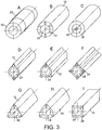
- Figures 3A to 3I show a number of examples of heat jackets suitable for use in the gas heater of Figure 2 .
- the heat jacket 12 is a circular cylinder and a heating collar 20 is shown arranged axially around the jacket 12.
- a central cylindrical bore 22 is provided within the jacket 12.
- the cylindrical bore 22 is for containing a filling medium such as a heat-conductor porous material acting as the heat exchanger.
- two or more axial bores 24 are provided to house heating rods. In use, a heating rod is inserted into one or more of the bores 24 of the high-pressure jacket 12. Thus, the jacket 12 is heated and this enables heat transfer to the filling medium 14 to occur.
- filling medium 26 is provided around a central heating element 28.
- heat is provided from the inside of the filling medium as opposed to from the outside.
- FIG 4 shows a section through a gas heater according to an example of an embodiment of the present invention.
- the heater 6 has a high-pressure jacket 12 and a filling medium 14 acting as a heat exchanger contained within it.
- an input 16 and an output 18 are provided to enable high-pressure gas to flow into and out of the heater, respectively.
- the heater 6 also has a plurality of flow deflectors 30 arranged within the jacket 12. In the example shown, five separate flow deflectors 30 are shown, although, it will be appreciated that any number may be provided.
- each flow deflector 30 comprises a disk fitted within the jacket 12.
- Each of the disks 30 has one or more through-holes 32 to provide a route and define a flow direction for gas as it passes through the heater 6.
- one through-hole is provided in each disk and the respective through-holes 32 of each of the disks 30 are staggered such that the gas is forced to take a torturous route through the heat exchanger 14. Accordingly, the residence time of the gas within the heater 6 is increased such that the efficiency of the heater is correspondingly increased.
- the route of the gas as it passes through the heater 6 is shown by arrows 34.
- the flow deflector 30 may be of any shape suitable for defining a tortuous route for gas flowing through the heat exchanger within the heater.
- the disks may be arranged such that they only contact a part of the jacket and gas can pass between the disk and the jacket where there is no contact between the disk and the jacket.
- each flow deflector 30 is made of a heat conductive material so that it is able to function as a heat distributor, i.e. conduct heat from the jacket 12 to within the heat exchanger 14. This increases the even nature of heat distribution within the filling medium 14.
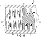
- FIG 5 shows a section through a through-flow gas heater 6 according to a further example of an embodiment of the present invention.
- the heater 6 in Figure 5 comprises a jacket 12 defining a housing having an inlet 16 and an outlet 18 to allow passage of high-pressure gas through the heater 6.
- the flow deflector 30 is preferably made from a solid heat-conductive material.
- the flow deflector is a spiral metallic element contained within the jacket 12.
- Porous filling medium 14 is provided in the spaces between the spiral turns of the heat deflector 30.
- heat is provided to the jacket 12 via a heat source (not shown).
- FIG. 6 shown an example of the flow deflector used in the heater 6 of Figure 5 .
- the flow deflector 30 has a coil 38 of width S 1 .
- the spacing or pitch between consecutive turns of the coil 38 is a distant S 2 .
- the overall diameter of the heat deflector is D 2 .
- the flow deflector 30 has a central shaft 40 of width D 1 . It will be appreciated that by varying any or all of S 1 , S 2 , D 1 and D 2 the overall performance of the heater can be changed.
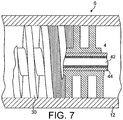
- Figure 7 shows a further example of a heater 6.
- a helical flow deflector 30 such as that shown in and described with reference to Figure 6 is provided within jacket 12.
- the flow deflector 30 is heat-conductive and has a central axial bore 42 within which is arranged a heating element 44.
- Figure 8 shows a view of another section through the heater of Figure 7 .
- the heater also comprises a locking element 46 provided in engagement with the inner wall of jacket 12.
- a mating thread 48 is provided between the locking element 46 and the jacket 12.
- the locking element 46 has a through-hole 50 arranged in use to coincide with an opening 52 at the right most end of flow deflector 30. This defines a passage for gas to leave the heater 6 after passage therethrough.
- the locking element 46 ensures that the flow deflector 30 is not forced out of the jacket 12 by the effect of the high-pressure gas it is arranged to receive.
- the heater 44 shown in Figure 8 is an electric heater and is provided with electric contacts 54 through which power may be provided to the heating element 44 such that it is able to provide heat to the heater 6. Any suitable type of heater may be used.
- the heat exchanger is preferably provided as a filling medium 40 such as a heat-conductive porous material.
- heat energy from a heat source is transferred from the jacket 12 to the porous heat exchanger through a cylindrical contact surface.
- heat transfer to the heat exchanger is also achieved through the flow deflector as well as through the cylindrical contact surface.
- the porous material is provided as a sintered or pressed material.
- the porous material is made up of a plurality of grains of the conductive porous material which can have any one of a number of desired shapes.
- Figures 9A to 9D show a number of examples of a section of the contact between the porous heat exchanger and the jacket of the heater. It can be seen that conductive bridges are formed between individual particles that enables heat to be transferred from the jacket 12 to within the porous material 14 via conduction.
- Figure 9A shows a situation in which the porous heat exchanger has been fitted within the jacket 12. In other words, it has been lightly placed within the jacket 12.
- the porous material 14 has been arranged with an interference fit with the jacket 12. In other words it has been forced into a jacket 12 with some considerable force. This causes an improvement in the amount of contact between the particles of the porous material 14 and the jacket 12.
- the porous material 14 prior to fitting into the jacket 12, is mechanically surface treated. In other words it is machined causing a deformation of grains and a consequent cylindrical surface of the porous material.
- the surface of the porous material is preferably closed so that an improved contact is achieved between the porous material 14 and the jacket 12.
- the porous material 14 has been pressed through a calibration ring to ensure it has a precisely defined size. This causes some deformation of the particles of the porous material that come into contact with the calibration ring as it is pushed through and so a good fit and good conductive engagement with the jacket 12 is achieved.
- the point to point contact between the individual particles of the porous material acts as a restriction for heat conduction through the sintered/porous material.
- the heat-conductive flow deflectors described above serve to increase the conduction of heat from the jacket 12 to within the heater 6.
- gas flowing through the heater is heated up with high efficiency due to the substantial heat transfer surface provided by the heat exchanger. Furthermore, if a heat deflector is used, transfer of heat to the heat exchanger can be improved and the route of gas flowing through the heater may be controlled to prolong the residence time of gas within the heater 6.
- the flow deflector is arranged so that it can divert the flow of gas within the heater 6.
- the flow of gas through the heater is such that at all times during the flow of gas, the distance between the flow of gas and a heat transfer surface through which the heat exchanger is arranged to receive heat, preferably remains substantially constant.
- the maximum temperature difference between the heat exchange surface of the heat exchanger and gas flowing through the heater is limited by the fact that it is desirable to maintain the outside surface temperature of the heater 6 or jacket 12 or the connections to the heater or jacket at a safe temperature, i.e. at a temperature at which a user will not be burned if direct contact is inadvertently made with the heater or jacket by a user's hand.
- a safe temperature i.e. at a temperature at which a user will not be burned if direct contact is inadvertently made with the heater or jacket by a user's hand.
- this difference can be larger. This is because in use a temperature gradient will exist between the heat source and part of the heater farthest from the heat source.
- the temperature gradient is such that the outside of the jacket 12 will be cooler than the heat source.
- the heat source can therefore be made hotter if it is arranged substantially along a central longitudinal axis of the heater 6. The heater efficiency per unit length of the heater therefore improves.
- any suitable heat source may be used with the heater and it may be integrally arranged within the heater and/or provided as a changeable or removable part. It is preferred that an electrical resistance cartridge is used fitted into either the solid heater jacket as described above with reference to Figures 3A to 3I or within a central core of a heat-conductive flow deflector 30 as described above with reference to Figures 7 and 8 . As an alternative, a heater jacket may be used, wrapped around the jacket 12. In the case of using an electrical resistance cartridge, the cartridge can be either the full length of the porous heat exchange element or only a partial length thereof. Other alternatives include the use of warm liquid or gas, steam, molten metal or radiation heat. In each case arrangement of the heater is such that the heat can be coupled to the heater from the heat source.
- Figure 10 is a graph showing the variation of temperature of a gas flowing through a gas supply apparatus as shown in either of Figures 1A or 1B .
- the graph shows the variation in temperature of gas for six different arrangements of heat source.
- the lines D and G show the situation in which the heat source or sources is or are off. As can be seen, as time progresses the temperature of the gas goes below -55°C due to the Joule-Thomson effect.
Landscapes
- Engineering & Computer Science (AREA)
- General Engineering & Computer Science (AREA)
- Mechanical Engineering (AREA)
- Physics & Mathematics (AREA)
- Thermal Sciences (AREA)
- Chemical & Material Sciences (AREA)
- Dispersion Chemistry (AREA)
- Heat-Exchange Devices With Radiators And Conduit Assemblies (AREA)
- Sampling And Sample Adjustment (AREA)
- Filling Or Discharging Of Gas Storage Vessels (AREA)
Claims (12)
- Gaserwärmer (6) zum Verbinden mit einer Wärmequelle und einer unter Druck stehenden Gasquelle, wobei der Gaserwärmer das Folgende umfasst:einen Mantel (12), der an einem ersten Ende einen Einlass (16) und an einem zweiten Ende einen Gasauslass aufweist und der dazwischen eine Höhlung definiert, wobei der Mantel (12) einen Zylinder umfasst, der aus einem wärmeleitenden Material hergestellt ist;einen porösen Wärmetauscher (14), der sich innerhalb der Höhlung erstreckt, und zwar vom Einlass zum Auslass; undMittel zum Bereitstellen von Wärme für den Wärmetauscher entlang seiner Länge;wobei der Wärmetauscher in wärmeleitender Kommunikation mit dem Mantel steht, um eine Übertragung von Wärme aus dem Mantel zu dem Wärmetauscher zu ermöglichen,dadurch gekennzeichnet, dass der Erwärmer einen Strömungsablenker (30) umfasst, der innerhalb des Mantels angeordnet ist, wobei der Strömungsablenker (30) in Verwendung so angeordnet ist, dass er Gas entlang eines turbulenten Wegs von dem ersten Ende des Mantels zu dem zweiten Ende davon durch den Wärmetauscher leitet, wobei der Strömungsablenker eine Scheibe oder ein Spiralgewinde umfasst.
- Gaserwärmer nach Anspruch 1, wobei der Wärmetauscher so angeordnet ist, dass er den Mantel (12) im Wesentlichen füllt.
- Gaserwärmer nach Anspruch 2, wobei der poröse Wärmetauscher (14) aus einem Material hergestellt ist, das aus der Gruppe ausgewählt ist, bestehend aus Kupfer, Messing, Bronze, Aluminium, Stahl, Edelstahl oder anderen eisenhaltigen oder nicht-eisenhaltigen Metallen und ihren Legierungen.
- Gaserwärmer nach Anspruch 3, wobei der poröse Wärmetauscher aus Körnern aus einem leitenden porösen Material hergestellt ist, wobei die Körner eines oder mehrere aus kugelförmig, einförmig, polyedrisch oder plattenförmig sind.
- Gaserwärmer nach Anspruch 4, wobei die Körner aus dem porösen Material durch eines oder beides aus Pressen und Sintern aneinandergebunden sind.
- Gaserwärmer nach Anspruch 6, wobei der Mantel aus einem wärmeleitenden Material hergestellt ist, das aus der Gruppe ausgewählt ist, bestehend aus Kupfer, Messing, Bronze, Aluminium, Stahl, Edelstahl oder ihren Legierungen und anderen eisenhaltigen und nicht-eisenhaltigen Metallen, wobei der Mantel mit Verbundmaterial verstärkt ist.
- Gaserwärmer nach Anspruch 1, wobei der Strömungsablenker wärmeleitend ist.
- Gaserwärmer nach Anspruch 1, wobei, wenn ein Spiralgewindeströmungsablenker bereitgestellt ist, der Spiralgewindeströmungsablenker eine im Wesentlichen zentrale Achsenbohrung (40) zum Aufnehmen von einer Wärmequelle umfasst.
- Gaserwärmer nach einem der Ansprüche 1 bis 8, umfassend eine Wärmequelle zum Bereitstellen von Wärme an den Erwärmer.
- Gasversorgungsapparat zum Verbindung mit einer unter Druck stehenden Gasquelle, wobei der Gasversorgungsapparat das Folgende umfasst:einen Gaserwärmer; undeinen Druckregulator, der einen Einlass aufweist, der mit einem Auslass des Gaserwärmers verbunden ist, wobei der Druckregulator angeordnet ist, um erwärmtes Gas aus dem Gaserwärmer aufzunehmen und den Druck davon zu regulieren, wobei der Gaserwärmer ein Gaserwärmer nach einem der Ansprüche 1 bis 9 ist.
- Gasversorgungsapparat nach Anspruch 10, umfassend ein oder mehrere unter Druck stehende Gasquellen, die damit verbunden sind.
- Verfahren zum Bereitstellen von Gas aus einer unter Druck stehenden Gasquelle, wobei das Verfahren das Folgende umfasst:Zuführen von Gas aus einer unter Druck stehenden Quelle zu einem Gaserwärmer;Zuführen von Gas aus dem Erwärmer zu einem Druckregulator, um den Druck davon zu regulieren, wobei der Gaserwärmer ein Gaserwärmer nach einem der Ansprüche 1 bis 9 ist.
Priority Applications (7)
| Application Number | Priority Date | Filing Date | Title |
|---|---|---|---|
| EP04252324.1A EP1589280B1 (de) | 2004-04-21 | 2004-04-21 | Gaserhitzer, Gaszuführvorrichtung und Verfahren |
| PT42523241T PT1589280T (pt) | 2004-04-21 | 2004-04-21 | Aquecedor a gás, aparelho de fornecimento de gás e método de proporcionar gás |
| PL04252324T PL1589280T3 (pl) | 2004-04-21 | 2004-04-21 | Grzejnik gazowy, urządzenie do doprowadzania gazu i sposób doprowadzania gazu |
| HUE04252324A HUE040444T2 (hu) | 2004-04-21 | 2004-04-21 | Gázmelegítõ egység, gázellátó berendezés, valamint gázszolgáltató eljárás |
| ES04252324.1T ES2683720T3 (es) | 2004-04-21 | 2004-04-21 | Un calentador de gas, un aparato de suministro de gas y un método para proporcionar gas |
| CA002503173A CA2503173C (en) | 2004-04-21 | 2005-04-18 | A gas heater, a gas supply apparatus and method of providing gas |
| US11/111,453 US7458807B2 (en) | 2004-04-21 | 2005-04-21 | Gas heater, a gas supply apparatus and a method of providing gas |
Applications Claiming Priority (1)
| Application Number | Priority Date | Filing Date | Title |
|---|---|---|---|
| EP04252324.1A EP1589280B1 (de) | 2004-04-21 | 2004-04-21 | Gaserhitzer, Gaszuführvorrichtung und Verfahren |
Publications (2)
| Publication Number | Publication Date |
|---|---|
| EP1589280A1 EP1589280A1 (de) | 2005-10-26 |
| EP1589280B1 true EP1589280B1 (de) | 2018-05-30 |
Family
ID=34930262
Family Applications (1)
| Application Number | Title | Priority Date | Filing Date |
|---|---|---|---|
| EP04252324.1A Expired - Lifetime EP1589280B1 (de) | 2004-04-21 | 2004-04-21 | Gaserhitzer, Gaszuführvorrichtung und Verfahren |
Country Status (7)
| Country | Link |
|---|---|
| US (1) | US7458807B2 (de) |
| EP (1) | EP1589280B1 (de) |
| CA (1) | CA2503173C (de) |
| ES (1) | ES2683720T3 (de) |
| HU (1) | HUE040444T2 (de) |
| PL (1) | PL1589280T3 (de) |
| PT (1) | PT1589280T (de) |
Families Citing this family (12)
| Publication number | Priority date | Publication date | Assignee | Title |
|---|---|---|---|---|
| US8015993B2 (en) * | 2004-10-18 | 2011-09-13 | GM Global Technology Operations LLC | Heatable hydrogen pressure regulator |
| DE102006019365A1 (de) * | 2006-04-21 | 2007-10-25 | Krautzberger Gmbh | Vorrichtung zum wasserdampfunterstützten Spritzen von Beschichtungsmaterial und Verfahren zum Beschichten von Substraten mit einem Beschichtungsmaterial |
| US8309874B2 (en) * | 2008-05-16 | 2012-11-13 | Applied Materials, Inc. | Gas heater |
| DE102012107600B4 (de) * | 2012-08-20 | 2015-10-08 | Borgwarner Ludwigsburg Gmbh | Elektrische Heizvorrichtung zum Beheizen von Fluiden |
| RS54053B1 (sr) * | 2012-09-10 | 2015-10-30 | Norma Germany Gmbh | Utisni priključak |
| KR102447439B1 (ko) * | 2017-04-25 | 2022-09-27 | 엘지전자 주식회사 | 수처리 장치용 온수생성모듈 |
| US11920878B2 (en) * | 2017-08-28 | 2024-03-05 | Watlow Electric Manufacturing Company | Continuous helical baffle heat exchanger |
| US11913736B2 (en) * | 2017-08-28 | 2024-02-27 | Watlow Electric Manufacturing Company | Continuous helical baffle heat exchanger |
| CN108151291A (zh) * | 2017-12-25 | 2018-06-12 | 上海科勒电子科技有限公司 | 一种直热式加热器 |
| DE102018113239A1 (de) * | 2018-06-04 | 2019-12-05 | Volkswagen Aktiengesellschaft | Zuführsystem zum Zuführen eines CNG- oder LNG-Kraftstoffes |
| SE546460C2 (en) * | 2021-04-22 | 2024-11-05 | Mann Teknik Ab | Device and method for drying a nozzle for liquified gas |
| CN119178103B (zh) * | 2024-11-26 | 2025-05-06 | 中国人民解放军空军勤务学院 | 一种便携式快速充氧氮气设备 |
Family Cites Families (12)
| Publication number | Priority date | Publication date | Assignee | Title |
|---|---|---|---|---|
| GB292395A (en) * | 1927-09-20 | 1928-06-21 | Rheostatic Co Ltd | Anti-freezing device for use with cylinders containing compressed gases |
| US2401797A (en) * | 1943-12-27 | 1946-06-11 | Gen Motors Corp | Heat exchanger |
| US3833791A (en) * | 1964-07-28 | 1974-09-03 | Schladitz Whiskers Ag | Resistance type fluid heating apparatus |
| DE3435319A1 (de) * | 1984-09-26 | 1986-04-03 | Michael 4150 Krefeld Laumen | Katalytischer dampferzeuger |
| EP0633423B1 (de) * | 1993-07-06 | 1997-01-15 | The Commonwealth Industrial Gases Limited | Vorrichtung zur Druckreduzierung und zur Massenstromregelung |
| US5443053A (en) * | 1993-07-27 | 1995-08-22 | Johnson; Jack E. | Fuel heater |
| GB9416822D0 (en) | 1994-08-19 | 1994-10-12 | Thompson Robert J | Toilet |
| US20010030040A1 (en) * | 1999-12-23 | 2001-10-18 | Jia Hua Xiao | Miniature cryogenic heat exchanger |
| US6345611B1 (en) * | 2000-05-11 | 2002-02-12 | Deere & Company | Thermostatically controlled heater for gas fuel and gas pressure regulator |
| DE10041992A1 (de) * | 2000-08-26 | 2002-03-14 | Gkn Sinter Metals Gmbh | Modul zur Verwendung als Filter, Katalysator oder Erhitzer sowie Verfahren zu seiner Herstellung |
| US20020108743A1 (en) * | 2000-12-11 | 2002-08-15 | Wirtz Richard A. | Porous media heat sink apparatus |
| JP2004301367A (ja) * | 2003-03-28 | 2004-10-28 | Aisin Seiki Co Ltd | 極低温発生装置 |
-
2004
- 2004-04-21 ES ES04252324.1T patent/ES2683720T3/es not_active Expired - Lifetime
- 2004-04-21 EP EP04252324.1A patent/EP1589280B1/de not_active Expired - Lifetime
- 2004-04-21 PL PL04252324T patent/PL1589280T3/pl unknown
- 2004-04-21 PT PT42523241T patent/PT1589280T/pt unknown
- 2004-04-21 HU HUE04252324A patent/HUE040444T2/hu unknown
-
2005
- 2005-04-18 CA CA002503173A patent/CA2503173C/en not_active Expired - Lifetime
- 2005-04-21 US US11/111,453 patent/US7458807B2/en not_active Expired - Lifetime
Non-Patent Citations (1)
| Title |
|---|
| None * |
Also Published As
| Publication number | Publication date |
|---|---|
| US7458807B2 (en) | 2008-12-02 |
| CA2503173C (en) | 2008-10-07 |
| PL1589280T3 (pl) | 2018-10-31 |
| US20050241632A1 (en) | 2005-11-03 |
| ES2683720T3 (es) | 2018-09-27 |
| CA2503173A1 (en) | 2005-10-21 |
| HUE040444T2 (hu) | 2019-03-28 |
| EP1589280A1 (de) | 2005-10-26 |
| PT1589280T (pt) | 2018-08-06 |
Similar Documents
| Publication | Publication Date | Title |
|---|---|---|
| US7458807B2 (en) | Gas heater, a gas supply apparatus and a method of providing gas | |
| US5949958A (en) | Integral flash steam generator | |
| CA2735836C (en) | Tube bundle heat exchanger for controlling a wide performance range | |
| US6955050B2 (en) | Thermal storage unit and methods for using the same to heat a fluid | |
| CA2220607C (en) | Heat exchanger | |
| EP2032266B1 (de) | Indirekt beheizter kapillarer aerosolerzeuger | |
| EP2462385B1 (de) | Vorrichtung zur lufterhitzung | |
| EP1666828A2 (de) | Wärmespeicher und dessen Verwendung zur Heizung einer Flüssigkeit | |
| JP5583021B2 (ja) | 高圧ガス貯蔵装置用の加温システム | |
| KR101821328B1 (ko) | 열교환 셀 세트의 제조방법 및 그 제조방법에 의해 제조된 열교환 셀 세트 | |
| US4723065A (en) | Electric automotive fuel heating system | |
| JP2009511102A (ja) | 家電装置用液体加熱デバイス | |
| US11761709B2 (en) | Heat exchanger | |
| CA2342551A1 (en) | Thermostatically controlled heater for gas fuel and gas pressure regulator | |
| US5267584A (en) | Method of fluid flow control using a porous media | |
| GB2102076A (en) | Thrust unit, especially for spacecraft | |
| JP2019196878A (ja) | 流体加熱装置 | |
| WO2023205122A1 (en) | Integrated heaters having nonlinear passageways for heating fluids, and apparatuses incorporating same | |
| US5175996A (en) | Apparatus for propellant flow control at low mass flow rates in zero G environment | |
| JP2022188976A (ja) | 蓄熱装置 | |
| CN220436206U (zh) | 一种可控温的外置换热型金属氢化物储氢瓶结构 | |
| CN114645756A (zh) | 用于将流体注射到排气管道中的装置和相关的排气系统 | |
| JP6888111B2 (ja) | 加圧装置 | |
| JPH0674688A (ja) | 特に腐食性流体のための熱交換器 | |
| GB2298478A (en) | Heat exchanger |
Legal Events
| Date | Code | Title | Description |
|---|---|---|---|
| PUAI | Public reference made under article 153(3) epc to a published international application that has entered the european phase |
Free format text: ORIGINAL CODE: 0009012 |
|
| AK | Designated contracting states |
Kind code of ref document: A1 Designated state(s): AT BE BG CH CY CZ DE DK EE ES FI FR GB GR HU IE IT LI LU MC NL PL PT RO SE SI SK TR |
|
| AX | Request for extension of the european patent |
Extension state: AL HR LT LV MK |
|
| 17P | Request for examination filed |
Effective date: 20051121 |
|
| AKX | Designation fees paid |
Designated state(s): AT BE BG CH CY CZ DE DK EE ES FI FR GB GR HU IE IT LI LU MC NL PL PT RO SE SI SK TR |
|
| 17Q | First examination report despatched |
Effective date: 20090127 |
|
| GRAP | Despatch of communication of intention to grant a patent |
Free format text: ORIGINAL CODE: EPIDOSNIGR1 |
|
| INTG | Intention to grant announced |
Effective date: 20180109 |
|
| GRAS | Grant fee paid |
Free format text: ORIGINAL CODE: EPIDOSNIGR3 |
|
| GRAA | (expected) grant |
Free format text: ORIGINAL CODE: 0009210 |
|
| AK | Designated contracting states |
Kind code of ref document: B1 Designated state(s): AT BE BG CH CY CZ DE DK EE ES FI FR GB GR HU IE IT LI LU MC NL PL PT RO SE SI SK TR |
|
| REG | Reference to a national code |
Ref country code: GB Ref legal event code: FG4D |
|
| REG | Reference to a national code |
Ref country code: CH Ref legal event code: EP |
|
| REG | Reference to a national code |
Ref country code: AT Ref legal event code: REF Ref document number: 1003958 Country of ref document: AT Kind code of ref document: T Effective date: 20180615 |
|
| REG | Reference to a national code |
Ref country code: IE Ref legal event code: FG4D |
|
| REG | Reference to a national code |
Ref country code: DE Ref legal event code: R096 Ref document number: 602004052758 Country of ref document: DE |
|
| REG | Reference to a national code |
Ref country code: PT Ref legal event code: SC4A Ref document number: 1589280 Country of ref document: PT Date of ref document: 20180806 Kind code of ref document: T Free format text: AVAILABILITY OF NATIONAL TRANSLATION Effective date: 20180731 |
|
| REG | Reference to a national code |
Ref country code: NL Ref legal event code: FP |
|
| REG | Reference to a national code |
Ref country code: ES Ref legal event code: FG2A Ref document number: 2683720 Country of ref document: ES Kind code of ref document: T3 Effective date: 20180927 |
|
| PG25 | Lapsed in a contracting state [announced via postgrant information from national office to epo] |
Ref country code: BG Free format text: LAPSE BECAUSE OF FAILURE TO SUBMIT A TRANSLATION OF THE DESCRIPTION OR TO PAY THE FEE WITHIN THE PRESCRIBED TIME-LIMIT Effective date: 20180830 Ref country code: FI Free format text: LAPSE BECAUSE OF FAILURE TO SUBMIT A TRANSLATION OF THE DESCRIPTION OR TO PAY THE FEE WITHIN THE PRESCRIBED TIME-LIMIT Effective date: 20180530 Ref country code: SE Free format text: LAPSE BECAUSE OF FAILURE TO SUBMIT A TRANSLATION OF THE DESCRIPTION OR TO PAY THE FEE WITHIN THE PRESCRIBED TIME-LIMIT Effective date: 20180530 Ref country code: CY Free format text: LAPSE BECAUSE OF FAILURE TO SUBMIT A TRANSLATION OF THE DESCRIPTION OR TO PAY THE FEE WITHIN THE PRESCRIBED TIME-LIMIT Effective date: 20180530 |
|
| PG25 | Lapsed in a contracting state [announced via postgrant information from national office to epo] |
Ref country code: GR Free format text: LAPSE BECAUSE OF FAILURE TO SUBMIT A TRANSLATION OF THE DESCRIPTION OR TO PAY THE FEE WITHIN THE PRESCRIBED TIME-LIMIT Effective date: 20180831 |
|
| REG | Reference to a national code |
Ref country code: AT Ref legal event code: MK05 Ref document number: 1003958 Country of ref document: AT Kind code of ref document: T Effective date: 20180530 |
|
| PG25 | Lapsed in a contracting state [announced via postgrant information from national office to epo] |
Ref country code: AT Free format text: LAPSE BECAUSE OF FAILURE TO SUBMIT A TRANSLATION OF THE DESCRIPTION OR TO PAY THE FEE WITHIN THE PRESCRIBED TIME-LIMIT Effective date: 20180530 Ref country code: EE Free format text: LAPSE BECAUSE OF FAILURE TO SUBMIT A TRANSLATION OF THE DESCRIPTION OR TO PAY THE FEE WITHIN THE PRESCRIBED TIME-LIMIT Effective date: 20180530 Ref country code: RO Free format text: LAPSE BECAUSE OF FAILURE TO SUBMIT A TRANSLATION OF THE DESCRIPTION OR TO PAY THE FEE WITHIN THE PRESCRIBED TIME-LIMIT Effective date: 20180530 Ref country code: DK Free format text: LAPSE BECAUSE OF FAILURE TO SUBMIT A TRANSLATION OF THE DESCRIPTION OR TO PAY THE FEE WITHIN THE PRESCRIBED TIME-LIMIT Effective date: 20180530 Ref country code: SK Free format text: LAPSE BECAUSE OF FAILURE TO SUBMIT A TRANSLATION OF THE DESCRIPTION OR TO PAY THE FEE WITHIN THE PRESCRIBED TIME-LIMIT Effective date: 20180530 |
|
| REG | Reference to a national code |
Ref country code: CH Ref legal event code: PK Free format text: BERICHTIGUNGEN |
|
| RIC2 | Information provided on ipc code assigned after grant |
Ipc: F17C 13/10 20060101AFI20041012BHEP Ipc: F28F 13/00 20060101ALI20041012BHEP Ipc: F28D 7/02 20060101ALI20041012BHEP |
|
| REG | Reference to a national code |
Ref country code: DE Ref legal event code: R097 Ref document number: 602004052758 Country of ref document: DE |
|
| REG | Reference to a national code |
Ref country code: HU Ref legal event code: AG4A Ref document number: E040444 Country of ref document: HU |
|
| PLBE | No opposition filed within time limit |
Free format text: ORIGINAL CODE: 0009261 |
|
| STAA | Information on the status of an ep patent application or granted ep patent |
Free format text: STATUS: NO OPPOSITION FILED WITHIN TIME LIMIT |
|
| 26N | No opposition filed |
Effective date: 20190301 |
|
| PG25 | Lapsed in a contracting state [announced via postgrant information from national office to epo] |
Ref country code: SI Free format text: LAPSE BECAUSE OF FAILURE TO SUBMIT A TRANSLATION OF THE DESCRIPTION OR TO PAY THE FEE WITHIN THE PRESCRIBED TIME-LIMIT Effective date: 20180530 |
|
| REG | Reference to a national code |
Ref country code: CH Ref legal event code: PL |
|
| PG25 | Lapsed in a contracting state [announced via postgrant information from national office to epo] |
Ref country code: LU Free format text: LAPSE BECAUSE OF NON-PAYMENT OF DUE FEES Effective date: 20190421 Ref country code: MC Free format text: LAPSE BECAUSE OF FAILURE TO SUBMIT A TRANSLATION OF THE DESCRIPTION OR TO PAY THE FEE WITHIN THE PRESCRIBED TIME-LIMIT Effective date: 20180530 |
|
| PG25 | Lapsed in a contracting state [announced via postgrant information from national office to epo] |
Ref country code: CH Free format text: LAPSE BECAUSE OF NON-PAYMENT OF DUE FEES Effective date: 20190430 Ref country code: LI Free format text: LAPSE BECAUSE OF NON-PAYMENT OF DUE FEES Effective date: 20190430 |
|
| PG25 | Lapsed in a contracting state [announced via postgrant information from national office to epo] |
Ref country code: TR Free format text: LAPSE BECAUSE OF FAILURE TO SUBMIT A TRANSLATION OF THE DESCRIPTION OR TO PAY THE FEE WITHIN THE PRESCRIBED TIME-LIMIT Effective date: 20180530 |
|
| PGFP | Annual fee paid to national office [announced via postgrant information from national office to epo] |
Ref country code: IE Payment date: 20230223 Year of fee payment: 20 Ref country code: FR Payment date: 20230309 Year of fee payment: 20 Ref country code: CZ Payment date: 20230329 Year of fee payment: 20 |
|
| PGFP | Annual fee paid to national office [announced via postgrant information from national office to epo] |
Ref country code: PL Payment date: 20230228 Year of fee payment: 20 Ref country code: IT Payment date: 20230310 Year of fee payment: 20 Ref country code: GB Payment date: 20230302 Year of fee payment: 20 Ref country code: BE Payment date: 20230315 Year of fee payment: 20 |
|
| P01 | Opt-out of the competence of the unified patent court (upc) registered |
Effective date: 20230515 |
|
| PGFP | Annual fee paid to national office [announced via postgrant information from national office to epo] |
Ref country code: NL Payment date: 20230314 Year of fee payment: 20 |
|
| PGFP | Annual fee paid to national office [announced via postgrant information from national office to epo] |
Ref country code: PT Payment date: 20230420 Year of fee payment: 20 Ref country code: ES Payment date: 20230511 Year of fee payment: 20 Ref country code: DE Payment date: 20230222 Year of fee payment: 20 |
|
| PGFP | Annual fee paid to national office [announced via postgrant information from national office to epo] |
Ref country code: HU Payment date: 20230308 Year of fee payment: 20 |
|
| REG | Reference to a national code |
Ref country code: DE Ref legal event code: R071 Ref document number: 602004052758 Country of ref document: DE |
|
| REG | Reference to a national code |
Ref country code: NL Ref legal event code: MK Effective date: 20240420 |
|
| PG25 | Lapsed in a contracting state [announced via postgrant information from national office to epo] |
Ref country code: ES Free format text: LAPSE BECAUSE OF EXPIRATION OF PROTECTION Effective date: 20240422 |
|
| REG | Reference to a national code |
Ref country code: ES Ref legal event code: FD2A Effective date: 20240426 |
|
| PG25 | Lapsed in a contracting state [announced via postgrant information from national office to epo] |
Ref country code: ES Free format text: LAPSE BECAUSE OF EXPIRATION OF PROTECTION Effective date: 20240422 |
|
| REG | Reference to a national code |
Ref country code: BE Ref legal event code: MK Effective date: 20240421 |
|
| REG | Reference to a national code |
Ref country code: GB Ref legal event code: PE20 Expiry date: 20240420 |
|
| REG | Reference to a national code |
Ref country code: IE Ref legal event code: MK9A |
|
| PG25 | Lapsed in a contracting state [announced via postgrant information from national office to epo] |
Ref country code: IE Free format text: LAPSE BECAUSE OF EXPIRATION OF PROTECTION Effective date: 20240421 |
|
| PG25 | Lapsed in a contracting state [announced via postgrant information from national office to epo] |
Ref country code: GB Free format text: LAPSE BECAUSE OF EXPIRATION OF PROTECTION Effective date: 20240420 |
|
| PG25 | Lapsed in a contracting state [announced via postgrant information from national office to epo] |
Ref country code: CZ Free format text: LAPSE BECAUSE OF EXPIRATION OF PROTECTION Effective date: 20240421 |
|
| PG25 | Lapsed in a contracting state [announced via postgrant information from national office to epo] |
Ref country code: IE Free format text: LAPSE BECAUSE OF EXPIRATION OF PROTECTION Effective date: 20240421 Ref country code: GB Free format text: LAPSE BECAUSE OF EXPIRATION OF PROTECTION Effective date: 20240420 Ref country code: CZ Free format text: LAPSE BECAUSE OF EXPIRATION OF PROTECTION Effective date: 20240421 |
|
| PG25 | Lapsed in a contracting state [announced via postgrant information from national office to epo] |
Ref country code: PT Free format text: LAPSE BECAUSE OF EXPIRATION OF PROTECTION Effective date: 20240503 |
|
| PG25 | Lapsed in a contracting state [announced via postgrant information from national office to epo] |
Ref country code: PT Free format text: LAPSE BECAUSE OF EXPIRATION OF PROTECTION Effective date: 20240503 |