EP1589238A1 - Verfahren zur Herstellung eines Bauteils mit einer bruchgetrennten Lageranordnung - Google Patents
Verfahren zur Herstellung eines Bauteils mit einer bruchgetrennten Lageranordnung Download PDFInfo
- Publication number
- EP1589238A1 EP1589238A1 EP05007187A EP05007187A EP1589238A1 EP 1589238 A1 EP1589238 A1 EP 1589238A1 EP 05007187 A EP05007187 A EP 05007187A EP 05007187 A EP05007187 A EP 05007187A EP 1589238 A1 EP1589238 A1 EP 1589238A1
- Authority
- EP
- European Patent Office
- Prior art keywords
- component
- connecting rod
- fracture
- recesses
- bearing
- Prior art date
- Legal status (The legal status is an assumption and is not a legal conclusion. Google has not performed a legal analysis and makes no representation as to the accuracy of the status listed.)
- Granted
Links
- 238000000034 method Methods 0.000 title claims abstract description 16
- 238000000926 separation method Methods 0.000 claims abstract description 21
- 239000011248 coating agent Substances 0.000 claims abstract description 8
- 238000000576 coating method Methods 0.000 claims abstract description 8
- 239000010410 layer Substances 0.000 claims description 18
- 238000004519 manufacturing process Methods 0.000 claims description 5
- 238000002360 preparation method Methods 0.000 claims description 5
- 230000003313 weakening effect Effects 0.000 claims description 5
- 239000002346 layers by function Substances 0.000 claims description 2
- 239000011247 coating layer Substances 0.000 description 4
- 239000010959 steel Substances 0.000 description 4
- 229910000831 Steel Inorganic materials 0.000 description 3
- 239000002184 metal Substances 0.000 description 3
- 229910052751 metal Inorganic materials 0.000 description 3
- 239000007858 starting material Substances 0.000 description 3
- 238000002485 combustion reaction Methods 0.000 description 2
- 239000002131 composite material Substances 0.000 description 2
- 230000001419 dependent effect Effects 0.000 description 2
- 230000000694 effects Effects 0.000 description 2
- 238000005242 forging Methods 0.000 description 2
- 230000001050 lubricating effect Effects 0.000 description 2
- 239000000463 material Substances 0.000 description 2
- 239000011156 metal matrix composite Substances 0.000 description 2
- 239000012791 sliding layer Substances 0.000 description 2
- 239000010936 titanium Substances 0.000 description 2
- 239000002966 varnish Substances 0.000 description 2
- 229910000906 Bronze Inorganic materials 0.000 description 1
- 229910001018 Cast iron Inorganic materials 0.000 description 1
- 229910001208 Crucible steel Inorganic materials 0.000 description 1
- RTAQQCXQSZGOHL-UHFFFAOYSA-N Titanium Chemical compound [Ti] RTAQQCXQSZGOHL-UHFFFAOYSA-N 0.000 description 1
- 229910045601 alloy Inorganic materials 0.000 description 1
- 239000000956 alloy Substances 0.000 description 1
- 229910052782 aluminium Inorganic materials 0.000 description 1
- XAGFODPZIPBFFR-UHFFFAOYSA-N aluminium Chemical compound [Al] XAGFODPZIPBFFR-UHFFFAOYSA-N 0.000 description 1
- 238000013459 approach Methods 0.000 description 1
- 239000010974 bronze Substances 0.000 description 1
- 238000005336 cracking Methods 0.000 description 1
- 238000011161 development Methods 0.000 description 1
- 230000018109 developmental process Effects 0.000 description 1
- 208000018459 dissociative disease Diseases 0.000 description 1
- 230000002349 favourable effect Effects 0.000 description 1
- 230000000977 initiatory effect Effects 0.000 description 1
- 239000007788 liquid Substances 0.000 description 1
- 229910001092 metal group alloy Inorganic materials 0.000 description 1
- 239000003973 paint Substances 0.000 description 1
- 230000036316 preload Effects 0.000 description 1
- 230000003014 reinforcing effect Effects 0.000 description 1
- 229910052719 titanium Inorganic materials 0.000 description 1
Images
Classifications
-
- F—MECHANICAL ENGINEERING; LIGHTING; HEATING; WEAPONS; BLASTING
- F16—ENGINEERING ELEMENTS AND UNITS; GENERAL MEASURES FOR PRODUCING AND MAINTAINING EFFECTIVE FUNCTIONING OF MACHINES OR INSTALLATIONS; THERMAL INSULATION IN GENERAL
- F16C—SHAFTS; FLEXIBLE SHAFTS; ELEMENTS OR CRANKSHAFT MECHANISMS; ROTARY BODIES OTHER THAN GEARING ELEMENTS; BEARINGS
- F16C9/00—Bearings for crankshafts or connecting-rods; Attachment of connecting-rods
- F16C9/04—Connecting-rod bearings; Attachments thereof
- F16C9/045—Connecting-rod bearings; Attachments thereof the bearing cap of the connecting rod being split by fracturing
Definitions
- the invention relates to a method for producing a component with a fracture-separated bearing assembly, being in preparation for fracture separation a near-surface and by means of in series via webs each other spaced-apart recesses formed weakening line is arranged and the component, in particular regions, with a as Sliding layer serving functional support is provided.
- a method for forming a tear point for fracture separation of a Component is known from DE 196 17 402 A1, according to the a fracture-separable connecting rod for an internal combustion engine a tear point in the large connecting rod eye by means of a series of embrittled webs created separate recesses, wherein first starter cracks for Break triggering emanating from the bridge tips.
- DE 196 17 402 A1 in a divisible by fracture separation Ductile metal component in a fracture separation plane for targeted Break initiation intended to form tear points such that over achieved the length of the respective tear point targeted distributed starter cracks are.
- a bearing is accommodated in the connecting rod eye, for example with Preload built-in, as a thin-wall bearing, consisting of Steel support shell, lead-bronze layer and galvanic overlay, executed connecting rod bearing shells.
- the bearing required in the connecting rod for example to form by a coating of the inner surface of the bearing eye.
- the object of the invention is to provide a method which under Avoiding the disadvantages described the preparation of an input allows said component.
- sustainable is a safer Ensures operation of the component as well as a process-safe and reproducible production are possible.
- the protection claim may also include features of the disclosure DE 196 17 402 A1 and / or WO 96/04485 A1, individually or in Combination, include.
- the functional support in the edge region of Wells has a reduced layer thickness.
- the webs between the depressions become advantageously by intersection of adjacent, funnel-shaped Wells are created and run to a point.
- the component with a 5 to 40 .mu.m, in particular about 15 to 25 microns, thick Gleitlacktik provided, which are wells formed like a blind hole and have a diameter of 0.08 to 0.4 mm, in particular from about 0.15 to 0.25 mm, on.
- the inventive method is characterized in that at Opening the fracture-separated bearing assembly, the functional layer starting from a region of reduced layer thickness breaks.
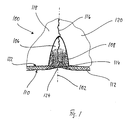
- FIG. 1 shows, in cross section, a component 100 separated into parts 118, 120.
- the component 100 is an in forging, Sintered or sintered forging process of steel or light metal, such as Aluminum (Al) or titanium (Ti) or a steel or light metal alloy or from a composite whose structure is a metallic one Alloy and a deliberately introduced reinforcing component consists of a metal rod, such as Metal Matrix Composites (MMC), for a Reciprocating internal combustion engine with a fracture-separated large Connecting rod eye, with a connecting rod bearing cap separated from the big end of the connecting rod.
- MMC Metal Matrix Composites
- the fracture separation plane 116 runs exactly as intended, is in the component 100 in preparation for fracture separation as a tear point 102 trained weakening line arranged.
- Tear points arranged diametrically opposite the bore inside.
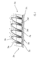
- FIG. 2 A longitudinal section through the tear point 202 in the component 200 is shown in FIG. 2. Near the surface and in series are spaced apart via webs 204 arranged recesses 106, 206 formed.
- the webs 204 between the recesses 106, 206 are defined by intersection of neighboring, funnel-shaped recesses 106, 206 generates and run to a point. From It is advantageous if the web tips at least approximately close come close to the component surface 122, 222 and / or against the Component surface 122, 222 are reset.
- the depressions 106, 206 are formed like a blind hole and have diameters of 0.08 to 0.4 mm, in particular from about 0.15 to 0.25 mm, on.
- a pulsed solid-state laser use Due to the small, locally limited heat input into the component 100, 200 are controlled Hardened layers produced, in particular, the tips of the webs 204 brittle.
- the component 100, 200 after the preparatory introduction the tear-off point 102, 202 fracture-separated, wherein the component along the Fracture separation plane 116 into parts 118, 120 breaks;
- the parts 118, 120 are reassembled and fixed after the fracture separation. Is it? in the component 100, 200 to a connecting rod with separated from the connecting rod foot Connecting rod bearing cap, connecting rod end and connecting rod bearing cover become together screwed.
- a mechanical (finish) processing of Connect components 100, 200 is optionally, a mechanical (finish) processing of Connect components 100, 200.
- the component 100, 200, 300 in assembled and fixed state with serving as a plain bearing functional support Mistake.
- the Functional support especially on the inside of the large connecting rod eye applied although it may well be appropriate, in addition to the small connecting rod eye and / or the lateral contact surfaces with a To provide functional overlay.
- the Component 100, 200, 300 appropriately cleaned after the fracture separation and / or degreased, optionally pickled, sandblasted, phosphated and / or plasma activated and / or preheated. Networked after application the Gleitlack Mrs 110, 210, 310, or cures, depending on used paint, for example, with heat in air.
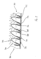
- the bonded coating forms over the joint of the fracture separation plane 116 continuous layer 110, 210, 310, wherein the Layer thickness due to the edge effect in conjunction with the Surface tension of the liquid applied lubricating varnish at each Recess 106, 206, 306 in the edge region 114, 214, 314 is less than in Area 112, 212, 312 of the flat surface; The lowest is the Layer thickness in the area 124 of the joint of the fracture separation plane 116. As a very It is considered favorable if the reduced layer thickness, in particular in the area of the joint of the fracture separation plane 116 approaches zero.
- the lubricating varnish partially runs into the depressions 106, 206, 306 and wets their upper edge regions 108, 208, 308; The reason of Recesses 106, 206, 306 is not wetted.
- the anti-friction coating 110, 210, 310 is only in the region of the webs 204, 304, in the range of the lowest Layer thickness, broken.
- the Bonded coating layer 110, 210, 310 already apply before the fracture separation. Even then arise with the inventive method advantages, it but must be paid particular attention to the fact that the Coating layer 110, 210, 310 not damaged during fracture separation becomes.
Landscapes
- Engineering & Computer Science (AREA)
- General Engineering & Computer Science (AREA)
- Mechanical Engineering (AREA)
- Shafts, Cranks, Connecting Bars, And Related Bearings (AREA)
Abstract
Description
- Figur 1
- ein Bauteil mit einer bruchgetrennten Lageranordnung mit einer Vertiefungen umfassenden Schwächungslinie und einer als Gleitlagerschicht dienenden Funktionsauflage,
- Figur 2
- ein Bauteil mit einer bruchgetrennten Lageranordnung mit einer oberflächennah und mittels in Reihe über Stege gegenseitig beabstandet angeordneter Vertiefungen ausgebildeter Schwächungslinie und einer als Gleitlagerschicht dienenden Funktionsauflage und
- Figur 3
- ein Bauteil mit einer bruchgetrennten Lageranordnung mit einer oberflächennah und mittels in Reihe über Stege gegenseitig beabstandet angeordneter Vertiefungen ausgebildeter Schwächungslinie und einer als Gleitlagerschicht dienenden Funktionsauflage.
Claims (8)
- Verfahren zur Herstellung eines Bauteils mit einer bruchgetrennten Lageranordnung, wobeidadurch gekennzeichnet, dass die Funktionsauflage (110, 210, 310) im Bereich (114, 124, 214, 314) der Bruchtrennfuge zumindest bereichsweise eine verringerte Schichtdicke aufweist.in Vorbereitung zum Bruchtrennen eine oberflächennah und mittels in Reihe über Stege gegenseitig beabstandet angeordneter Vertiefungen ausgebildete Schwächungslinie angeordnet wird unddas Bauteil, insbesondere bereichsweise, mit einer als Gleitlagerschicht dienenden Funktionsauflage versehen ist,
- Verfahren nach Anspruch 1, dadurch gekennzeichnet, dass die Funktionsauflage (110, 210, 310) im Kantenbereich (114, 214, 314) der Vertiefungen (106, 206, 306) eine verringerte Schichtdicke aufweist.
- Verfahren nach Anspruch 1 oder 2, dadurch gekennzeichnet, dass, zwischen der Bauteiloberfläche (122, 222, 322) und den Vertiefungen (106, 206, 306) scharfe Kanten (114, 214, 314) gebildet sind.
- Verfahren nach einem der vorhergehenden Ansprüche, dadurch gekennzeichnet, dass die Stege (204, 304) zwischen den Vertiefungen (106, 206, 306) durch Verschneidung benachbarter, trichterförmiger Vertiefungen (106, 206, 306) erzeugt werden und spitz zulaufen.
- Verfahren nach einem der vorhergehenden Ansprüche, dadurch gekennzeichnet, dass das Bauteil (100, 200, 300) mit einer 5 bis 40 µm, insbesondere ca. 15 bis 25 µm, dicken Gleitlackschicht (110, 210, 310) versehen wird.
- Verfahren nach einem der vorhergehenden Ansprüche, dadurch gekennzeichnet, dass die Vertiefungen (106, 206, 306) sacklochartig ausgebildet sind und einen Durchmesser von 0,08 bis 0,4 mm, insbesondere von ca. 0,15 bis 0,25 mm, aufweisen.
- Verfahren nach einem der vorhergehenden Ansprüche, dadurch gekennzeichnet, dass beim Öffnen der bruchgetrennten Lageranordnung die Funktionsschicht (110, 210, 310) ausgehend von einem Bereich (114, 124, 214, 314) verringerter Schichtdicke bricht.
- Verfahren nach einem der vorhergehenden Ansprüche, dadurch gekennzeichnet, dass das Bauteil (100, 200, 300) eine Pleuelstange für einen eine Kurbelwelle umfassenden Hubkolbenmotor mit einem der Kurbelwelle zugeordneten bruchtrennbaren Pleuelauge ist, wobei vom Pleuelfuß ein Pleuellagerdeckel trennbar ist und im Pleuelauge die Funktionsauflage (110, 210, 310) durch Beschichtung zumindest der Innenfläche des Pleuelauges gebildet ist.
Applications Claiming Priority (2)
| Application Number | Priority Date | Filing Date | Title |
|---|---|---|---|
| DE102004018922 | 2004-04-20 | ||
| DE200410018922 DE102004018922A1 (de) | 2004-04-20 | 2004-04-20 | Verfahren zur Herstellung eines Bauteils mit einer bruchgetrennten Lageranordnung |
Publications (2)
| Publication Number | Publication Date |
|---|---|
| EP1589238A1 true EP1589238A1 (de) | 2005-10-26 |
| EP1589238B1 EP1589238B1 (de) | 2009-03-18 |
Family
ID=34934690
Family Applications (1)
| Application Number | Title | Priority Date | Filing Date |
|---|---|---|---|
| EP20050007187 Ceased EP1589238B1 (de) | 2004-04-20 | 2005-04-01 | Verfahren zur Herstellung eines Bauteils mit einer bruchgetrennten Lageranordnung |
Country Status (2)
| Country | Link |
|---|---|
| EP (1) | EP1589238B1 (de) |
| DE (2) | DE102004018922A1 (de) |
Cited By (1)
| Publication number | Priority date | Publication date | Assignee | Title |
|---|---|---|---|---|
| DE102006051641A1 (de) * | 2006-11-02 | 2008-05-08 | Schaeffler Kg | Wälzlager für trockenlaufende oder mediengeschmierte Anwendungen |
Citations (5)
| Publication number | Priority date | Publication date | Assignee | Title |
|---|---|---|---|---|
| WO1996004485A1 (de) * | 1994-08-01 | 1996-02-15 | Gerold Pankl | Pleuelstange |
| DE19617402A1 (de) * | 1995-12-19 | 1997-06-26 | Bayerische Motoren Werke Ag | Verfahren zur Ausbildung einer Anrißstelle zum Bruchtrennen eines Bauteils, insbesondere Pleuel für Brennkraftmaschinen |
| EP0863322A1 (de) * | 1997-03-04 | 1998-09-09 | Volkswagen Aktiengesellschaft | Verfahren zum Herstellen eines Pleuels |
| US6379754B1 (en) * | 1997-07-28 | 2002-04-30 | Volkswagen Ag | Method for thermal coating of bearing layers |
| DE10102641A1 (de) * | 2001-01-20 | 2002-07-25 | Bayerische Motoren Werke Ag | Werkstoffverbung-Bauteil mit einer Bruchfläche sowie Verfahren zur Vorbereitung einer Bruchtrennstelle |
Family Cites Families (3)
| Publication number | Priority date | Publication date | Assignee | Title |
|---|---|---|---|---|
| DE19751640A1 (de) * | 1997-11-21 | 1999-05-27 | Bayerische Motoren Werke Ag | Geschmiedetes Pleuel für Hubkolbenmaschinen aus Kohlenstoffstahl mit bruchgetrenntem Lagerdeckel |
| DE19838745A1 (de) * | 1998-08-26 | 2000-03-09 | Daimler Chrysler Ag | Gleitlager mit einem Lagerstuhl und einem Lagerdeckel |
| AT412168B (de) * | 2002-10-04 | 2004-10-25 | Miba Gleitlager Gmbh | Verfahren zum herstellen eines wenigstens ein lagerauge bildenden werkstückes |
-
2004
- 2004-04-20 DE DE200410018922 patent/DE102004018922A1/de not_active Withdrawn
-
2005
- 2005-04-01 EP EP20050007187 patent/EP1589238B1/de not_active Ceased
- 2005-04-01 DE DE200550006857 patent/DE502005006857D1/de not_active Expired - Lifetime
Patent Citations (5)
| Publication number | Priority date | Publication date | Assignee | Title |
|---|---|---|---|---|
| WO1996004485A1 (de) * | 1994-08-01 | 1996-02-15 | Gerold Pankl | Pleuelstange |
| DE19617402A1 (de) * | 1995-12-19 | 1997-06-26 | Bayerische Motoren Werke Ag | Verfahren zur Ausbildung einer Anrißstelle zum Bruchtrennen eines Bauteils, insbesondere Pleuel für Brennkraftmaschinen |
| EP0863322A1 (de) * | 1997-03-04 | 1998-09-09 | Volkswagen Aktiengesellschaft | Verfahren zum Herstellen eines Pleuels |
| US6379754B1 (en) * | 1997-07-28 | 2002-04-30 | Volkswagen Ag | Method for thermal coating of bearing layers |
| DE10102641A1 (de) * | 2001-01-20 | 2002-07-25 | Bayerische Motoren Werke Ag | Werkstoffverbung-Bauteil mit einer Bruchfläche sowie Verfahren zur Vorbereitung einer Bruchtrennstelle |
Cited By (1)
| Publication number | Priority date | Publication date | Assignee | Title |
|---|---|---|---|---|
| DE102006051641A1 (de) * | 2006-11-02 | 2008-05-08 | Schaeffler Kg | Wälzlager für trockenlaufende oder mediengeschmierte Anwendungen |
Also Published As
| Publication number | Publication date |
|---|---|
| DE502005006857D1 (de) | 2009-04-30 |
| DE102004018922A1 (de) | 2005-11-17 |
| EP1589238B1 (de) | 2009-03-18 |
Similar Documents
| Publication | Publication Date | Title |
|---|---|---|
| EP3090188B1 (de) | Stanzniet | |
| DE102008022225A1 (de) | Verfahren zum Behandeln einer Oberfläche | |
| DE102007048753A1 (de) | Pleuelstange für einen Verbrennungsmotor und Verfahren zum Herstellen der Pleuelstange | |
| EP2529878A1 (de) | Verfahren zum Herstellen einer Pressverbindung zwischen zwei Bauteilen und Bauteileverbund aus zwei Bauteilen | |
| DE102012104172B4 (de) | Verfahren zur Herstellung eines bezogen auf das Gewicht leichten, aber hinsichtlich der Beanspruchung stark belasteten Bauteils sowie Bauteil hergestellt mit diesem Verfahren | |
| DE10035032C2 (de) | Verfahren zur Herstellung eines Pleuels | |
| DE10233263B4 (de) | Verfahren zur Herstellung eines Pleuels und Pleuel | |
| DE102005034306A1 (de) | Verfahren zur Herstellung eines Kolbens einer Brennkraftmaschine zur Bildung einer Bewehrung einer Brennraummulde des Kolbens | |
| AT518517A2 (de) | Verfahren zum Bearbeiten einer Oberfläche eines metallischen Bauteils und metallisches Bauteil | |
| EP1589238B1 (de) | Verfahren zur Herstellung eines Bauteils mit einer bruchgetrennten Lageranordnung | |
| DE10360148A1 (de) | Zylinderlaufbahn und Verfahren zur Herstellung einer Zylinderlaufbahn | |
| DE102018107716A1 (de) | Laser-umschmelzung zur verbesserung mechanischer eigenschaften von zylinderbohrungen | |
| EP2441549A2 (de) | Verfahren zur mechanischen Bearbeitung eines abgasführenden Oberflächenbereichs eines Brennkraftmaschinen- oder Kurbelgehäusebestandteils sowie Brennkraftmaschinen-Kurbelgehäuse und Zylinderlaufbuchse | |
| EP1955799B1 (de) | Verfahren zur Ausbildung einer Anrissstelle zum Bruchtrennen eines Bauteils aus einem Kohlenstoffstahl | |
| EP1034868B1 (de) | Verfahren zur Ausbildung einer Anrissstelle zum Bruchtrennen eines Bauteiles aus einem Kohlenstoffstahl | |
| DE102006019341B3 (de) | Axialzapfen, vorzugsweise zur Verwendung als Spurstangenbauteil | |
| DE102005031335B4 (de) | Verfahren zum Herstellen von Bruchtrennkerben und Werkstück | |
| DE10045174B4 (de) | Verfahren zur Herstellung eines Kolbens | |
| DE102012001057A1 (de) | Bauteil | |
| EP1225348B1 (de) | Werkstoffverbund-Bauteil mit einer Bruchfläche sowie Verfahren zur Vorbereitung einer Bruchtrennstelle | |
| DE102009021067B4 (de) | Dünnwandige Einlage für einen Zylinder einer Kolbenmaschine und eine Zylinderlaufbuchse, Zylinder und Motorblock einer Kolbenmaschine, sowie Verfahren zu deren Herstellung | |
| DE102005046061A1 (de) | Hebel einer schaltbaren Schlepphebelvorrichtung und Verfahren zur Herstellung desselben | |
| EP3009701B1 (de) | Bruchgetrenntes bauteil, insbesondere bruchgetrenntes pleuel oder bruchgetrennter hauptlagerdeckel eines kurbelgehäuses einer brennkraftmaschine | |
| DE102014004344A1 (de) | Verfahren zur Herstellung eines Leichtbauteils, Leichtbauteil und Blecheinleger | |
| WO2018202542A1 (de) | Verfahren zum bearbeiten eines zylinders |
Legal Events
| Date | Code | Title | Description |
|---|---|---|---|
| PUAI | Public reference made under article 153(3) epc to a published international application that has entered the european phase |
Free format text: ORIGINAL CODE: 0009012 |
|
| AK | Designated contracting states |
Kind code of ref document: A1 Designated state(s): AT BE BG CH CY CZ DE DK EE ES FI FR GB GR HU IE IS IT LI LT LU MC NL PL PT RO SE SI SK TR |
|
| AX | Request for extension of the european patent |
Extension state: AL BA HR LV MK YU |
|
| 17P | Request for examination filed |
Effective date: 20051109 |
|
| AKX | Designation fees paid |
Designated state(s): DE FR GB IT |
|
| GRAP | Despatch of communication of intention to grant a patent |
Free format text: ORIGINAL CODE: EPIDOSNIGR1 |
|
| GRAS | Grant fee paid |
Free format text: ORIGINAL CODE: EPIDOSNIGR3 |
|
| GRAA | (expected) grant |
Free format text: ORIGINAL CODE: 0009210 |
|
| AK | Designated contracting states |
Kind code of ref document: B1 Designated state(s): DE FR GB IT |
|
| REG | Reference to a national code |
Ref country code: GB Ref legal event code: FG4D Free format text: NOT ENGLISH |
|
| REF | Corresponds to: |
Ref document number: 502005006857 Country of ref document: DE Date of ref document: 20090430 Kind code of ref document: P |
|
| PLBE | No opposition filed within time limit |
Free format text: ORIGINAL CODE: 0009261 |
|
| STAA | Information on the status of an ep patent application or granted ep patent |
Free format text: STATUS: NO OPPOSITION FILED WITHIN TIME LIMIT |
|
| 26N | No opposition filed |
Effective date: 20091221 |
|
| REG | Reference to a national code |
Ref country code: FR Ref legal event code: PLFP Year of fee payment: 12 |
|
| REG | Reference to a national code |
Ref country code: FR Ref legal event code: PLFP Year of fee payment: 13 |
|
| PGFP | Annual fee paid to national office [announced via postgrant information from national office to epo] |
Ref country code: FR Payment date: 20170424 Year of fee payment: 13 Ref country code: GB Payment date: 20170425 Year of fee payment: 13 Ref country code: DE Payment date: 20170427 Year of fee payment: 13 |
|
| PGFP | Annual fee paid to national office [announced via postgrant information from national office to epo] |
Ref country code: IT Payment date: 20170420 Year of fee payment: 13 |
|
| REG | Reference to a national code |
Ref country code: DE Ref legal event code: R119 Ref document number: 502005006857 Country of ref document: DE |
|
| GBPC | Gb: european patent ceased through non-payment of renewal fee |
Effective date: 20180401 |
|
| PG25 | Lapsed in a contracting state [announced via postgrant information from national office to epo] |
Ref country code: DE Free format text: LAPSE BECAUSE OF NON-PAYMENT OF DUE FEES Effective date: 20181101 |
|
| PG25 | Lapsed in a contracting state [announced via postgrant information from national office to epo] |
Ref country code: GB Free format text: LAPSE BECAUSE OF NON-PAYMENT OF DUE FEES Effective date: 20180401 |
|
| PG25 | Lapsed in a contracting state [announced via postgrant information from national office to epo] |
Ref country code: FR Free format text: LAPSE BECAUSE OF NON-PAYMENT OF DUE FEES Effective date: 20180430 Ref country code: IT Free format text: LAPSE BECAUSE OF NON-PAYMENT OF DUE FEES Effective date: 20180401 |