EP1589228A1 - Pumpe mit regelbarer Liefermenge - Google Patents
Pumpe mit regelbarer Liefermenge Download PDFInfo
- Publication number
- EP1589228A1 EP1589228A1 EP05103251A EP05103251A EP1589228A1 EP 1589228 A1 EP1589228 A1 EP 1589228A1 EP 05103251 A EP05103251 A EP 05103251A EP 05103251 A EP05103251 A EP 05103251A EP 1589228 A1 EP1589228 A1 EP 1589228A1
- Authority
- EP
- European Patent Office
- Prior art keywords
- pump device
- spindle
- component
- temperature
- heat
- Prior art date
- Legal status (The legal status is an assumption and is not a legal conclusion. Google has not performed a legal analysis and makes no representation as to the accuracy of the status listed.)
- Granted
Links
- 239000012530 fluid Substances 0.000 claims abstract description 41
- 239000007788 liquid Substances 0.000 claims abstract description 9
- 239000000470 constituent Substances 0.000 claims description 12
- 238000006073 displacement reaction Methods 0.000 claims description 6
- 230000000295 complement effect Effects 0.000 claims description 2
- 230000006835 compression Effects 0.000 claims description 2
- 238000007906 compression Methods 0.000 claims description 2
- ZZUFCTLCJUWOSV-UHFFFAOYSA-N furosemide Chemical compound C1=C(Cl)C(S(=O)(=O)N)=CC(C(O)=O)=C1NCC1=CC=CO1 ZZUFCTLCJUWOSV-UHFFFAOYSA-N 0.000 claims description 2
- 230000008018 melting Effects 0.000 claims description 2
- 238000002844 melting Methods 0.000 claims description 2
- 238000004519 manufacturing process Methods 0.000 description 3
- 238000012986 modification Methods 0.000 description 2
- 230000004048 modification Effects 0.000 description 2
- 230000001105 regulatory effect Effects 0.000 description 2
- 230000005540 biological transmission Effects 0.000 description 1
- 230000007257 malfunction Effects 0.000 description 1
- 238000006467 substitution reaction Methods 0.000 description 1
- 230000001131 transforming effect Effects 0.000 description 1
Images


Classifications
-
- F—MECHANICAL ENGINEERING; LIGHTING; HEATING; WEAPONS; BLASTING
- F04—POSITIVE - DISPLACEMENT MACHINES FOR LIQUIDS; PUMPS FOR LIQUIDS OR ELASTIC FLUIDS
- F04D—NON-POSITIVE-DISPLACEMENT PUMPS
- F04D15/00—Control, e.g. regulation, of pumps, pumping installations or systems
- F04D15/0027—Varying behaviour or the very pump
- F04D15/0038—Varying behaviour or the very pump by varying the effective cross-sectional area of flow through the rotor
Definitions
- the present invention relates to the field of regulation, more particularly the regulation of the output of a liquid or viscous fluid, in relation to the use of a device for circulating said fluid, such as a pump or similar.
- the object of the present invention is a pump device of which the output is a function of the temperature of the fluid delivered, at least within a predetermined temperature range.
- a first known solution consists of measuring the temperature of the fluid by a suitable sensor and varying the speed of the motor driving the active component of the pump depending on the measured temperature, after processing the measured values.
- a second known solution consists of measuring the temperature of the fluid by a suitable sensor and displacing or positioning an obstruction element depending on the measured temperature, to modify the pump's inlet and/or outlet section, to modify the useful surface of the active component, or to modify the characteristics of the chamber of the housing of said pump, it then being possible for the speed of the active component and its actuating means to remain constant.
- the object of the present invention in particular is to overcome the aforementioned drawbacks.
- the present invention relates to a variable output pump device, comprising a movable component capable of displacing a liquid fluid, said movable component being driven at a constant speed by a motor, a similar actuating means or a means of transmitting movement, said movable component being mounted in a chamber of a housing comprising a supply passage or orifice and an outlet passage, the output of the pump device being variable depending on the temperature of the liquid fluid aspirated and delivered by said device, at least within a certain temperature range, a pump device characterised in that it also comprises a heat-sensitive component mounted in the supply passage or orifice or in the outlet passage, the apparent surface in a projection plane perpendicular to the direction of the fluid flow of said heat-sensitive component being a function of the temperature of said fluid with which it is in direct contact.
- variable output pump device 1 comprises a housing 5, 5' and a movable component 2 capable of displacing a liquid fluid, said movable component being driven at a constant speed by a motor 3, a similar actuating means or a means of movement transmission, said movable component 2 being mounted in a chamber 4 of the housing comprising a supply passage or orifice 6 and an outlet passage 7, the output of the pump device 1 being variable depending on the temperature of the liquid fluid aspirated and delivered by said device, at least within a certain temperature range.
- said pump device 1 also comprises a heat-sensitive component 8 mounted in the supply passage or orifice 6 or in the outlet passage 7, the apparent surface in a projection plane perpendicular to the fluid flow direction of said heat-sensitive component 8 being a function of the temperature of said fluid with which it is in direct contact.
- variable output pump is achieved with an extremely simple structure (that is to say only slightly more complex than a constant output pump and that could possibly be manufactured easily from a constant output pump) and that does not require a variable actuator, the heat-sensitive component 8 fulfilling simultaneously the function of sensor, transducer and output regulating component.
- heat-sensitive component existing standard components are favoured, advantageously those of simple design and low manufacturing cost, capable of directly transforming temperature variations into variations of position or form, according to a predetermined function, and that can possibly be adjusted according to the application envisaged and the variations desired.
- Modification of the apparent surface of the heat-sensitive component 8, exposed to the fluid flow may be achieved by different physical variations, namely variation of position (pivoting a plate round a spindle), variation of external form (greater or lesser deployment of constituent parts), variation of volume (greater or lesser inflation), variation of internal form (greater or lesser restriction in the region of a traversing orifice arranged in the heat-sensitive component).
- the heat-sensitive component 8 may comprise a body 9 forming an envelope or box, of which the external form changes depending on variations in the temperature of the fluid flow to which said component 8 is directly exposed, in particular the area of its apparent surface exposed to the fluid flow or obtained by projection in a plane perpendicular to the direction of said flow.
- the heat-sensitive component 8 may comprise a body 9 forming an envelope or box of which the external form is such that its apparent surface exposed to the fluid flow or obtained by projection in a plane perpendicular to the direction of said flow varies if there is a displacement of said body 9 generated by and a function of a variation in temperature of said fluid to which said component 8 is directly exposed.
- the heat-sensitive component 8 may comprise a part 9, if applicable a body 9 forming an envelope or box, for example of non-regular, non-symmetrical structure or provided with excrescence(s), mounted moving round a spindle, the degree of pivoting or the position in rotation round said spindle being a function of the temperature of the fluid to which said heat-sensitive component 8 is directly exposed.
- the heat-sensitive component to be basically composed of at least two parts 9 and 9' of different section and assembled together telescopically, said component 8 being mounted transversally in the outlet passage 7 and the telescopic structure forming it being retracted for low temperatures, with maximum obstruction of the outlet passage 7 by the part 9 of larger section, and deployed for higher temperatures, with total or partial displacement of the part 9 of greater section outside said passage 7 and exposure to the fluid flow traversing said passage 7 of the part(s) 9' of smaller section.
- the telescopic structure of the heat-sensitive component 8 is subject to an elastic constraint loading it in its state of maximum retraction, the temperature-sensitive actuating means of the component 8 (for example wax) acting positively against said elastic constraint with a magnitude corresponding to the magnitude of the rise in temperature.
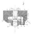
- the component 8 may consist of a wax actuator, also known currently as a thermostatic element or wax plug, comprising, on the one hand, a cylindrical box body 9 enclosing a predetermined quantity of wax forming the temperature-sensitive actuating means of which the melting temperature is substantially equal to the lower temperature of the active regulation range and, on the other hand, a spindle 9' mounted moving in translation in said box body 9, between a position of maximum retraction and a position of maximum extension, and of which the position in translation is determined by the condition of the wax.
- a wax actuator also known currently as a thermostatic element or wax plug
- Said wax actuator 8 is mounted in said outlet passage 7 of the chamber 4 of the pump device 1 with the free end 9" of the spindle 9' mounted fixed in a side recess 10 of the wall 10' of said passage 7 and its box body 9 mounted sliding in a bearing 11 of the housing, said box body 9 being subject to an elastic load in the direction of the free end 9" of the spindle 9'.
- the pump device 1 may comprise a preassembled module 12 incorporating a box 13 comprising a compression spring 14 applying an elastic load to the box body 9 of the heat-sensitive component 8, or to a drive or support part 14' integral therewith, mounted sliding and coming to a stop in the position of maximum displacement in the action direction of the spring 14 and in that said module 12 is received sealed in a suitable recess arranged in the housing 5, 5' of the pump device 1.
- a movable component 2 to consist of a finned wheel mounted on a rotating drive spindle 2' and for the housing to be formed principally of two complementary parts 5 and 5' assembled together and sealed in the region of a joint plane 5", the first part 5 having a totally or at least partly discoid cavity 15 in which the supply passage 6 and the outlet passage 7 open out and the second part 5' in the form of a cover closing said cavity 15 to delimit the chamber 4 and forming directly or indirectly a support for the rotating spindle 2' on which is mounted projecting the finned wheel 2, the supply passage 6 opening into the chamber 4 in the direction of the rotating spindle 2' and facing that spindle and the outlet passage 7 extending tangentially from the circular periphery of said chamber.
- the outlet passage 7 is formed in the first constituent part 5 of the housing and the preassembled module 12 is mounted sealed by its box 5 in the second constituent part 5' forming a cover and by the end 9" of its spindle 9' movable in translation in a recess 10 of the wall 10' delimiting the outlet passage 7 of the first constituent part 5.
- the outlet passage 7 is at least partially formed in a structural extension 16 of the second part 5' constituting the housing, which is nested and sealed in a corresponding reception recess 16' of the first constituent part 5, so as to delimit in part the chamber 4.
- the preassembled module 12 is then mounted sealed by its box 13 in the second constituent part 5' and by the end 9" of its spindle 9' movable in translation in a recess 10 of the wall 10' delimiting the outlet passage 7 and forming part of said structural extension 16, the wax actuator 8 being thus permanently in contact over the whole of its external surface with the fluid.
- FIG. 4 of the accompanying drawings shows a hybrid variant of the two aforementioned variants.
- the driving of the spindle 2' of the movable component 2 may be produced by a belt, a chain or similar means of transmitting a rotating movement.
- an electric motor 3 which may or may not be of variable speed, is mounted in the second part 5' forming a cover, its spindle 2' carrying the movable component 2 mounted fixed in rotation on this spindle.
- the heat-sensitive component 8 consists of a shape-memorising part, mounted transversally in the supply 6 or outlet 7 passage and of which the apparent surface exposed to the flow of fluid varies, by changing the orientation or form of said part, depending on the temperature of said fluid in contact with it, at least within a predetermined temperature range.
Landscapes
- Engineering & Computer Science (AREA)
- Mechanical Engineering (AREA)
- General Engineering & Computer Science (AREA)
- Control Of Positive-Displacement Pumps (AREA)
- Details Of Reciprocating Pumps (AREA)
- Steroid Compounds (AREA)
- Seal Device For Vehicle (AREA)
- Reciprocating Pumps (AREA)
- Temperature-Responsive Valves (AREA)
Applications Claiming Priority (2)
| Application Number | Priority Date | Filing Date | Title |
|---|---|---|---|
| FR0404346A FR2869370B1 (fr) | 2004-04-23 | 2004-04-23 | Dispositif de pompe a debit variable |
| FR0404346 | 2004-04-23 |
Publications (2)
| Publication Number | Publication Date |
|---|---|
| EP1589228A1 true EP1589228A1 (de) | 2005-10-26 |
| EP1589228B1 EP1589228B1 (de) | 2008-04-09 |
Family
ID=34939440
Family Applications (1)
| Application Number | Title | Priority Date | Filing Date |
|---|---|---|---|
| EP05103251A Expired - Lifetime EP1589228B1 (de) | 2004-04-23 | 2005-04-21 | Pumpe mit regelbarer Liefermenge |
Country Status (5)
| Country | Link |
|---|---|
| US (1) | US20050238498A1 (de) |
| EP (1) | EP1589228B1 (de) |
| AT (1) | ATE391853T1 (de) |
| DE (1) | DE602005005890T2 (de) |
| FR (1) | FR2869370B1 (de) |
Cited By (2)
| Publication number | Priority date | Publication date | Assignee | Title |
|---|---|---|---|---|
| WO2012003357A3 (en) * | 2010-07-01 | 2012-04-26 | Micropump, Inc. | Pumps and pump heads comprising volume-compensation feature |
| WO2019053377A1 (fr) | 2017-09-18 | 2019-03-21 | Sogefi Air & Cooling | Dispositif de pompe a debit variable et circuit comprenant une telle pompe |
Families Citing this family (5)
| Publication number | Priority date | Publication date | Assignee | Title |
|---|---|---|---|---|
| ITBS20130100A1 (it) * | 2013-07-09 | 2015-01-10 | Ind Saleri Italo Spa | Pompa di raffreddamento regolabile per motore a combustione interna |
| DE112015004301B4 (de) | 2014-09-22 | 2025-02-06 | Industrie Saleri Italo S.P.A. | Ventilgruppe mit axial bewegbarem Verschluss |
| DE102015000805B3 (de) * | 2015-01-22 | 2016-01-21 | Nidec Gpm Gmbh | Regelbare Kühlmittelpumpe |
| DE102015208354B3 (de) | 2015-05-06 | 2016-03-24 | Magna powertrain gmbh & co kg | Fluid-Fördersystem |
| KR20190072934A (ko) * | 2017-12-18 | 2019-06-26 | 현대자동차주식회사 | 차량용 워터 펌프 |
Citations (4)
| Publication number | Priority date | Publication date | Assignee | Title |
|---|---|---|---|---|
| FR2681906A1 (fr) * | 1991-09-27 | 1993-04-02 | Renault Vehicules Ind | Pompe centrifuge pour circuit de liquide de refroidissement de moteur a combustion. |
| FR2738203A1 (fr) * | 1995-08-31 | 1997-03-07 | Valeo Systemes Dessuyage | Dispositif de projection de liquide de lavage a trois voies pour vehicule automobile |
| DE19823603A1 (de) * | 1998-05-27 | 1999-12-02 | Behr Thermot Tronik Gmbh & Co | Vorrichtung zum Steuern der Kühlmitteltemperatur eines Verbrennungsmotors eines Fahrzeuges |
| US6260515B1 (en) * | 1998-10-05 | 2001-07-17 | Honda Giken Kogyo Kabushiki Kaisha | Engine cooling system |
Family Cites Families (10)
| Publication number | Priority date | Publication date | Assignee | Title |
|---|---|---|---|---|
| US1704481A (en) * | 1926-08-17 | 1929-03-05 | Worthington Pump & Mach Corp | Rotary machine, particularly in centrifugal pump |
| US2462198A (en) * | 1940-07-01 | 1949-02-22 | Roger C Johnson | Thermostatic valve |
| DE1910090A1 (de) * | 1969-02-28 | 1970-11-05 | Bosch Gmbh Robert | Kraftstoffeinspritzpumpe fuer Brennkraftmaschinen |
| US4029074A (en) * | 1975-12-04 | 1977-06-14 | Robertshaw Controls Company | Fuel valves |
| JPS5564460U (de) * | 1978-10-27 | 1980-05-02 | ||
| US4426196A (en) * | 1981-09-16 | 1984-01-17 | Hobourn-Eaton Limited | Oil supply system |
| JPS60198386A (ja) * | 1984-03-21 | 1985-10-07 | Matsushita Electric Ind Co Ltd | 能力可変圧縮機 |
| US4789301A (en) * | 1986-03-27 | 1988-12-06 | Goulds Pumps, Incorporated | Low specific speed pump casing construction |
| US6887046B2 (en) * | 1996-02-26 | 2005-05-03 | Flowork Systems Ii Llc | Coolant pump, mainly for automotive use |
| US6772958B1 (en) * | 2003-04-28 | 2004-08-10 | Rostra Precision Controls, Inc. | Thermal flow control valve |
-
2004
- 2004-04-23 FR FR0404346A patent/FR2869370B1/fr not_active Expired - Fee Related
-
2005
- 2005-04-21 DE DE602005005890T patent/DE602005005890T2/de not_active Expired - Lifetime
- 2005-04-21 EP EP05103251A patent/EP1589228B1/de not_active Expired - Lifetime
- 2005-04-21 AT AT05103251T patent/ATE391853T1/de not_active IP Right Cessation
- 2005-04-22 US US11/111,956 patent/US20050238498A1/en not_active Abandoned
Patent Citations (4)
| Publication number | Priority date | Publication date | Assignee | Title |
|---|---|---|---|---|
| FR2681906A1 (fr) * | 1991-09-27 | 1993-04-02 | Renault Vehicules Ind | Pompe centrifuge pour circuit de liquide de refroidissement de moteur a combustion. |
| FR2738203A1 (fr) * | 1995-08-31 | 1997-03-07 | Valeo Systemes Dessuyage | Dispositif de projection de liquide de lavage a trois voies pour vehicule automobile |
| DE19823603A1 (de) * | 1998-05-27 | 1999-12-02 | Behr Thermot Tronik Gmbh & Co | Vorrichtung zum Steuern der Kühlmitteltemperatur eines Verbrennungsmotors eines Fahrzeuges |
| US6260515B1 (en) * | 1998-10-05 | 2001-07-17 | Honda Giken Kogyo Kabushiki Kaisha | Engine cooling system |
Cited By (4)
| Publication number | Priority date | Publication date | Assignee | Title |
|---|---|---|---|---|
| WO2012003357A3 (en) * | 2010-07-01 | 2012-04-26 | Micropump, Inc. | Pumps and pump heads comprising volume-compensation feature |
| US8734139B2 (en) | 2010-07-01 | 2014-05-27 | Micropump, Inc. | Pumps and pump heads comprising volume-compensation feature |
| WO2019053377A1 (fr) | 2017-09-18 | 2019-03-21 | Sogefi Air & Cooling | Dispositif de pompe a debit variable et circuit comprenant une telle pompe |
| US11168694B2 (en) | 2017-09-18 | 2021-11-09 | Sogefi Air & Cooling | Variable-delivery pump device and circuit including such a pump |
Also Published As
| Publication number | Publication date |
|---|---|
| EP1589228B1 (de) | 2008-04-09 |
| DE602005005890T2 (de) | 2009-06-04 |
| US20050238498A1 (en) | 2005-10-27 |
| FR2869370A1 (fr) | 2005-10-28 |
| DE602005005890D1 (de) | 2008-05-21 |
| ATE391853T1 (de) | 2008-04-15 |
| FR2869370B1 (fr) | 2008-08-22 |
Similar Documents
| Publication | Publication Date | Title |
|---|---|---|
| US4903643A (en) | Temperature-sensing fan fluid coupling | |
| US6669439B2 (en) | Variable flow impeller-type water pump with movable shroud | |
| EP1589228B1 (de) | Pumpe mit regelbarer Liefermenge | |
| JP2000213492A (ja) | 特に自動車用の冷媒を搬送するための調節可能なラジアルポンプ | |
| US20090235766A1 (en) | Actuator With Integrated Drive Mechanism | |
| US20090160275A1 (en) | Actuator With Integrated Drive Mechanism | |
| KR20010112247A (ko) | 좌석 벨트 수축 장치 | |
| EP1729031A3 (de) | Rotationsdämpfer, Kraftfahrzeugteil mit einem Rotationsdämpfer sowie Mechanismus zur Dämpfung eines Drehvorgangs | |
| CN102333956A (zh) | 直接控制线性变排量叶片泵 | |
| US20160222963A1 (en) | Variable displacement pump with electric control of displacement regulation and method of regulating pump displacement | |
| US10648468B2 (en) | Adjustable vane pump | |
| JPS59131040A (ja) | 内燃機関の冷却空気フアン用の液体摩擦クラツチ | |
| JP3040431B2 (ja) | 回転振動緩衝装置における流体状の緩衝媒体の時間的流量を変化させるための装置 | |
| JPH0488219A (ja) | 温度感応型流体式カツプリング装置 | |
| EP1653311B1 (de) | Vorrichtung zum automatischen Regeln eines Durchflusses und Kreislauf mit einer Vorrichtung dieser Art | |
| ITBO990595A1 (it) | Corpo farfallato . | |
| RU2182996C2 (ru) | Термостатическая насадка для вентиля | |
| JPH0488220A (ja) | 温度感応型流体式カツプリング装置 | |
| WO2005095821A1 (ja) | ロータリーダンパ | |
| ITTO990873A1 (it) | Pompa rotativa a cilindrata fissa e portata variabile, particolarmente per olio. | |
| JP2007309377A (ja) | 回転ダンパ−装置 | |
| JPH062069Y2 (ja) | 車輌用伸縮駆動装置 | |
| US11899474B2 (en) | Temperature sensor for coolant control valve | |
| JP2002106607A (ja) | ファンカップリング装置 | |
| JP2007278451A (ja) | 流体継手 |
Legal Events
| Date | Code | Title | Description |
|---|---|---|---|
| PUAI | Public reference made under article 153(3) epc to a published international application that has entered the european phase |
Free format text: ORIGINAL CODE: 0009012 |
|
| AK | Designated contracting states |
Kind code of ref document: A1 Designated state(s): AT BE BG CH CY CZ DE DK EE ES FI FR GB GR HU IE IS IT LI LT LU MC NL PL PT RO SE SI SK TR |
|
| AX | Request for extension of the european patent |
Extension state: AL BA HR LV MK YU |
|
| 17P | Request for examination filed |
Effective date: 20060421 |
|
| AKX | Designation fees paid |
Designated state(s): AT BE BG CH CY CZ DE DK EE ES FI FR GB GR HU IE IS IT LI LT LU MC NL PL PT RO SE SI SK TR |
|
| 17Q | First examination report despatched |
Effective date: 20060710 |
|
| 17Q | First examination report despatched |
Effective date: 20060710 |
|
| GRAP | Despatch of communication of intention to grant a patent |
Free format text: ORIGINAL CODE: EPIDOSNIGR1 |
|
| GRAS | Grant fee paid |
Free format text: ORIGINAL CODE: EPIDOSNIGR3 |
|
| GRAA | (expected) grant |
Free format text: ORIGINAL CODE: 0009210 |
|
| AK | Designated contracting states |
Kind code of ref document: B1 Designated state(s): AT BE BG CH CY CZ DE DK EE ES FI FR GB GR HU IE IS IT LI LT LU MC NL PL PT RO SE SI SK TR |
|
| REG | Reference to a national code |
Ref country code: GB Ref legal event code: FG4D |
|
| REG | Reference to a national code |
Ref country code: CH Ref legal event code: EP |
|
| REG | Reference to a national code |
Ref country code: IE Ref legal event code: FG4D |
|
| REF | Corresponds to: |
Ref document number: 602005005890 Country of ref document: DE Date of ref document: 20080521 Kind code of ref document: P |
|
| PG25 | Lapsed in a contracting state [announced via postgrant information from national office to epo] |
Ref country code: SI Free format text: LAPSE BECAUSE OF FAILURE TO SUBMIT A TRANSLATION OF THE DESCRIPTION OR TO PAY THE FEE WITHIN THE PRESCRIBED TIME-LIMIT Effective date: 20080409 |
|
| NLV1 | Nl: lapsed or annulled due to failure to fulfill the requirements of art. 29p and 29m of the patents act | ||
| PG25 | Lapsed in a contracting state [announced via postgrant information from national office to epo] |
Ref country code: ES Free format text: LAPSE BECAUSE OF FAILURE TO SUBMIT A TRANSLATION OF THE DESCRIPTION OR TO PAY THE FEE WITHIN THE PRESCRIBED TIME-LIMIT Effective date: 20080720 Ref country code: FI Free format text: LAPSE BECAUSE OF FAILURE TO SUBMIT A TRANSLATION OF THE DESCRIPTION OR TO PAY THE FEE WITHIN THE PRESCRIBED TIME-LIMIT Effective date: 20080409 Ref country code: BG Free format text: LAPSE BECAUSE OF FAILURE TO SUBMIT A TRANSLATION OF THE DESCRIPTION OR TO PAY THE FEE WITHIN THE PRESCRIBED TIME-LIMIT Effective date: 20080709 Ref country code: PT Free format text: LAPSE BECAUSE OF FAILURE TO SUBMIT A TRANSLATION OF THE DESCRIPTION OR TO PAY THE FEE WITHIN THE PRESCRIBED TIME-LIMIT Effective date: 20080910 Ref country code: NL Free format text: LAPSE BECAUSE OF FAILURE TO SUBMIT A TRANSLATION OF THE DESCRIPTION OR TO PAY THE FEE WITHIN THE PRESCRIBED TIME-LIMIT Effective date: 20080409 |
|
| PG25 | Lapsed in a contracting state [announced via postgrant information from national office to epo] |
Ref country code: MC Free format text: LAPSE BECAUSE OF NON-PAYMENT OF DUE FEES Effective date: 20080430 Ref country code: PL Free format text: LAPSE BECAUSE OF FAILURE TO SUBMIT A TRANSLATION OF THE DESCRIPTION OR TO PAY THE FEE WITHIN THE PRESCRIBED TIME-LIMIT Effective date: 20080409 Ref country code: AT Free format text: LAPSE BECAUSE OF FAILURE TO SUBMIT A TRANSLATION OF THE DESCRIPTION OR TO PAY THE FEE WITHIN THE PRESCRIBED TIME-LIMIT Effective date: 20080409 |
|
| ET | Fr: translation filed | ||
| PG25 | Lapsed in a contracting state [announced via postgrant information from national office to epo] |
Ref country code: IS Free format text: LAPSE BECAUSE OF FAILURE TO SUBMIT A TRANSLATION OF THE DESCRIPTION OR TO PAY THE FEE WITHIN THE PRESCRIBED TIME-LIMIT Effective date: 20080809 |
|
| PG25 | Lapsed in a contracting state [announced via postgrant information from national office to epo] |
Ref country code: LT Free format text: LAPSE BECAUSE OF FAILURE TO SUBMIT A TRANSLATION OF THE DESCRIPTION OR TO PAY THE FEE WITHIN THE PRESCRIBED TIME-LIMIT Effective date: 20080409 Ref country code: EE Free format text: LAPSE BECAUSE OF FAILURE TO SUBMIT A TRANSLATION OF THE DESCRIPTION OR TO PAY THE FEE WITHIN THE PRESCRIBED TIME-LIMIT Effective date: 20080409 Ref country code: SE Free format text: LAPSE BECAUSE OF FAILURE TO SUBMIT A TRANSLATION OF THE DESCRIPTION OR TO PAY THE FEE WITHIN THE PRESCRIBED TIME-LIMIT Effective date: 20080709 Ref country code: DK Free format text: LAPSE BECAUSE OF FAILURE TO SUBMIT A TRANSLATION OF THE DESCRIPTION OR TO PAY THE FEE WITHIN THE PRESCRIBED TIME-LIMIT Effective date: 20080409 Ref country code: CZ Free format text: LAPSE BECAUSE OF FAILURE TO SUBMIT A TRANSLATION OF THE DESCRIPTION OR TO PAY THE FEE WITHIN THE PRESCRIBED TIME-LIMIT Effective date: 20080409 |
|
| PLBE | No opposition filed within time limit |
Free format text: ORIGINAL CODE: 0009261 |
|
| STAA | Information on the status of an ep patent application or granted ep patent |
Free format text: STATUS: NO OPPOSITION FILED WITHIN TIME LIMIT |
|
| PG25 | Lapsed in a contracting state [announced via postgrant information from national office to epo] |
Ref country code: RO Free format text: LAPSE BECAUSE OF FAILURE TO SUBMIT A TRANSLATION OF THE DESCRIPTION OR TO PAY THE FEE WITHIN THE PRESCRIBED TIME-LIMIT Effective date: 20080409 Ref country code: BE Free format text: LAPSE BECAUSE OF FAILURE TO SUBMIT A TRANSLATION OF THE DESCRIPTION OR TO PAY THE FEE WITHIN THE PRESCRIBED TIME-LIMIT Effective date: 20080409 Ref country code: SK Free format text: LAPSE BECAUSE OF FAILURE TO SUBMIT A TRANSLATION OF THE DESCRIPTION OR TO PAY THE FEE WITHIN THE PRESCRIBED TIME-LIMIT Effective date: 20080409 |
|
| 26N | No opposition filed |
Effective date: 20090112 |
|
| PG25 | Lapsed in a contracting state [announced via postgrant information from national office to epo] |
Ref country code: IE Free format text: LAPSE BECAUSE OF NON-PAYMENT OF DUE FEES Effective date: 20080421 |
|
| PG25 | Lapsed in a contracting state [announced via postgrant information from national office to epo] |
Ref country code: CY Free format text: LAPSE BECAUSE OF FAILURE TO SUBMIT A TRANSLATION OF THE DESCRIPTION OR TO PAY THE FEE WITHIN THE PRESCRIBED TIME-LIMIT Effective date: 20080409 |
|
| REG | Reference to a national code |
Ref country code: CH Ref legal event code: PL |
|
| GBPC | Gb: european patent ceased through non-payment of renewal fee |
Effective date: 20090421 |
|
| PG25 | Lapsed in a contracting state [announced via postgrant information from national office to epo] |
Ref country code: CH Free format text: LAPSE BECAUSE OF NON-PAYMENT OF DUE FEES Effective date: 20090430 Ref country code: LI Free format text: LAPSE BECAUSE OF NON-PAYMENT OF DUE FEES Effective date: 20090430 |
|
| PG25 | Lapsed in a contracting state [announced via postgrant information from national office to epo] |
Ref country code: GB Free format text: LAPSE BECAUSE OF NON-PAYMENT OF DUE FEES Effective date: 20090421 |
|
| PG25 | Lapsed in a contracting state [announced via postgrant information from national office to epo] |
Ref country code: LU Free format text: LAPSE BECAUSE OF NON-PAYMENT OF DUE FEES Effective date: 20080421 Ref country code: HU Free format text: LAPSE BECAUSE OF FAILURE TO SUBMIT A TRANSLATION OF THE DESCRIPTION OR TO PAY THE FEE WITHIN THE PRESCRIBED TIME-LIMIT Effective date: 20081010 |
|
| PG25 | Lapsed in a contracting state [announced via postgrant information from national office to epo] |
Ref country code: TR Free format text: LAPSE BECAUSE OF FAILURE TO SUBMIT A TRANSLATION OF THE DESCRIPTION OR TO PAY THE FEE WITHIN THE PRESCRIBED TIME-LIMIT Effective date: 20080409 |
|
| PG25 | Lapsed in a contracting state [announced via postgrant information from national office to epo] |
Ref country code: GR Free format text: LAPSE BECAUSE OF FAILURE TO SUBMIT A TRANSLATION OF THE DESCRIPTION OR TO PAY THE FEE WITHIN THE PRESCRIBED TIME-LIMIT Effective date: 20080710 |
|
| PGFP | Annual fee paid to national office [announced via postgrant information from national office to epo] |
Ref country code: IT Payment date: 20080430 Year of fee payment: 4 |
|
| PGFP | Annual fee paid to national office [announced via postgrant information from national office to epo] |
Ref country code: DE Payment date: 20120426 Year of fee payment: 8 |
|
| PG25 | Lapsed in a contracting state [announced via postgrant information from national office to epo] |
Ref country code: DE Free format text: LAPSE BECAUSE OF NON-PAYMENT OF DUE FEES Effective date: 20131101 |
|
| REG | Reference to a national code |
Ref country code: DE Ref legal event code: R119 Ref document number: 602005005890 Country of ref document: DE Effective date: 20131101 |
|
| REG | Reference to a national code |
Ref country code: FR Ref legal event code: PLFP Year of fee payment: 12 |
|
| REG | Reference to a national code |
Ref country code: FR Ref legal event code: PLFP Year of fee payment: 13 |
|
| REG | Reference to a national code |
Ref country code: FR Ref legal event code: PLFP Year of fee payment: 14 |
|
| PGFP | Annual fee paid to national office [announced via postgrant information from national office to epo] |
Ref country code: FR Payment date: 20240426 Year of fee payment: 20 |