EP1588966A1 - Dispositif d'alignement d'éléments en plaque dans une machine les travaillant - Google Patents
Dispositif d'alignement d'éléments en plaque dans une machine les travaillant Download PDFInfo
- Publication number
- EP1588966A1 EP1588966A1 EP04405243A EP04405243A EP1588966A1 EP 1588966 A1 EP1588966 A1 EP 1588966A1 EP 04405243 A EP04405243 A EP 04405243A EP 04405243 A EP04405243 A EP 04405243A EP 1588966 A1 EP1588966 A1 EP 1588966A1
- Authority
- EP
- European Patent Office
- Prior art keywords
- cheek
- plate elements
- carrier element
- guide member
- conveyor
- Prior art date
- Legal status (The legal status is an assumption and is not a legal conclusion. Google has not performed a legal analysis and makes no representation as to the accuracy of the status listed.)
- Granted
Links
- 230000001105 regulatory effect Effects 0.000 claims description 2
- 230000002441 reversible effect Effects 0.000 claims description 2
- 241000287828 Gallus gallus Species 0.000 description 9
- 235000013330 chicken meat Nutrition 0.000 description 9
- 210000000056 organ Anatomy 0.000 description 6
- 238000011144 upstream manufacturing Methods 0.000 description 6
- 238000004519 manufacturing process Methods 0.000 description 5
- 238000005520 cutting process Methods 0.000 description 4
- 238000004026 adhesive bonding Methods 0.000 description 3
- 239000011111 cardboard Substances 0.000 description 3
- 239000000463 material Substances 0.000 description 2
- 230000036515 potency Effects 0.000 description 2
- 238000003825 pressing Methods 0.000 description 2
- 125000006850 spacer group Chemical group 0.000 description 2
- 230000001154 acute effect Effects 0.000 description 1
- 238000005452 bending Methods 0.000 description 1
- 238000010276 construction Methods 0.000 description 1
- 239000000428 dust Substances 0.000 description 1
- 230000000694 effects Effects 0.000 description 1
- 238000000034 method Methods 0.000 description 1
- 238000003801 milling Methods 0.000 description 1
- 238000004806 packaging method and process Methods 0.000 description 1
- 239000011087 paperboard Substances 0.000 description 1
- 239000000725 suspension Substances 0.000 description 1
- 230000003313 weakening effect Effects 0.000 description 1
Images


Classifications
-
- B—PERFORMING OPERATIONS; TRANSPORTING
- B65—CONVEYING; PACKING; STORING; HANDLING THIN OR FILAMENTARY MATERIAL
- B65H—HANDLING THIN OR FILAMENTARY MATERIAL, e.g. SHEETS, WEBS, CABLES
- B65H9/00—Registering, e.g. orientating, articles; Devices therefor
- B65H9/16—Inclined tape, roller, or like article-forwarding side registers
- B65H9/166—Roller
-
- B—PERFORMING OPERATIONS; TRANSPORTING
- B31—MAKING ARTICLES OF PAPER, CARDBOARD OR MATERIAL WORKED IN A MANNER ANALOGOUS TO PAPER; WORKING PAPER, CARDBOARD OR MATERIAL WORKED IN A MANNER ANALOGOUS TO PAPER
- B31B—MAKING CONTAINERS OF PAPER, CARDBOARD OR MATERIAL WORKED IN A MANNER ANALOGOUS TO PAPER
- B31B50/00—Making rigid or semi-rigid containers, e.g. boxes or cartons
- B31B50/02—Feeding or positioning sheets, blanks or webs
- B31B50/04—Feeding sheets or blanks
- B31B50/044—Feeding sheets or blanks involving aligning
-
- B—PERFORMING OPERATIONS; TRANSPORTING
- B31—MAKING ARTICLES OF PAPER, CARDBOARD OR MATERIAL WORKED IN A MANNER ANALOGOUS TO PAPER; WORKING PAPER, CARDBOARD OR MATERIAL WORKED IN A MANNER ANALOGOUS TO PAPER
- B31B—MAKING CONTAINERS OF PAPER, CARDBOARD OR MATERIAL WORKED IN A MANNER ANALOGOUS TO PAPER
- B31B50/00—Making rigid or semi-rigid containers, e.g. boxes or cartons
- B31B50/02—Feeding or positioning sheets, blanks or webs
- B31B50/10—Feeding or positioning webs
- B31B50/104—Feeding or positioning webs involving aligning
Definitions
- the present invention relates to a device for aligning elements in plate in a machine working them, especially in a machine intended for the manufacture of packaging such as a folder-gluer.
- a folder-gluer usually includes a suite modules, each intended to perform a specific operation so as to that the cuts, introduced at the entrance of the machine, come out in the form of folded boxes ready for use.
- a folder-gluer includes usually a feeder feeding the machine in box cutouts from of a pile of poses.
- the conveying of these cuts in the different modules of the machine is provided by a conveyor belt which, by friction, seized the cutouts, either between lower and upper belts, or between lower belts and upper pinch rollers.
- operations performed during the machine are: the pre-breaking of some folding lines of the cut, the folding of certain parts, the gluing of the legs gluing, pressing the cutouts once folded and glued and receiving them in end of production line.
- Box cutting during the introduction momentarily obstructs the space existing between the lower end of the gauge and the surface of the belts so as to prevent the departure of the next cut until the rear edge of the cutout being introduced has left the existing space under the gauge. Because the friction force existing between the cut of the bottom of the stack and belts is much larger than that existing between two cuts, even at the bottom of the pile, the introduction can be perfectly controlled. However, these friction naturally generate wear of cuttings causing the appearance of a cardboard dust that eventually clogs the drive belts and can influence the grip of the elements in plate. Depending on the format of the box cutouts, several belts can be arranged parallel to each other to ensure their transport.
- a plurality of pressure rollers are arranged along a bar placed above the drive belt.
- the set is arranged in a movable carriage in the lateral direction in order to adapt to the different possible formats leaves.
- the orientation of the belt may vary due to the arrangement of a bearing supporting one of the end pulleys of the drive and swivel belt around a vertical axis.
- the bar supporting the support rollers is also rotated so that it can be oriented at the same angle than that of the drive belt.
- Document CH678'707 describes another cut alignment device box comprising a displaceable longitudinal guide rail, a belt without lower end driven and supported by pebbles, and a series of pebbles superior, each mounted in vertical and horizontal pivoting so that it is no only possible to lower or raise each roller to adjust its pressure on the cut, but also possible to steer independently each of them in a chosen direction.
- this device has the disadvantage of being particularly expensive and complicated to achieve.
- the multiple possibilities adjustment make it a device that can become relatively long to handle.
- this device comprises a lower carrier mounted on a spar lower and, in correspondence, a higher carrier subject to adjustment to an upper spar.
- a stem connects the lower spar with upper spar so that the angular adjustment of the lower conveyors and higher can be achieved simultaneously.
- one of the ends of the lower spar is pivotally mounted in the horizontal plane on a part fixed frame by means of a vertical axis pivot.
- a device including screw and threaded ring allows to separate this end of the longitudinal rail of guiding and thereby varying the angle of orientation of the torque of lower and upper conveyors relative to the longitudinal reference axis.
- the present invention proposes an alignment device which is particularly economical to manufacture, simpler to make and that can be used indifferently for an alignment said right or left while not requiring a minimum of handling to achieve such a reversal.
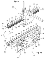
- FIGS. 1a, 1b and 2a, 2b show in perspective a device 1 for aligning plate elements, not shown, according to views respectively on the opposite side and on the driver's side of the machine.
- the arrow F indicates the direction of movement of the plate elements and allows also define the upstream and downstream sides of the device 1 by specifying that the Plate elements always move from upstream to downstream.
- the definition of this terminology allows as much as possible to avoid the use of the terms left-right and front-back who have the disadvantage of depending on the position of the observer compared to the machine considered.
- the adjectives longitudinal and lateral or transversal, as well as derived adverbs refer to the position of pieces respectively oriented in the upstream-downstream direction and in the driver side direction - opposite driver side.
- the device 1 is presented in a configuration adapted for alignment of the plate elements on the side opposite driver of a folder-gluer, namely for a so-called correction to right.
- the folder-gluer not forming part of the present invention and bringing nothing to the understanding of the device 1, it is voluntarily has not been shown in the accompanying figures.
- the choice to want illustrate the device 1 of the present invention in a configuration provided for an opposite side driver rather than driver side alignment only stems because the alignment of the plate elements is in the vast majority of case performed on the right. Nevertheless, the right-left inversion of this configuration will be explained later in the following description.
- the alignment device 1 consists of two distinct parts illustrated for one in Figures 1a, 2a and for the other in Figures 1b, 2b.
- FIGS. 1b and 2b show a lower rectifying member 10 corresponding to the lower part of the device 1
- FIGS. 1a and 2a show an organ upper rectifier 60 removable and corresponding to the upper part of this same device 1.
- the plane of passage 2 of the plate elements is between the rectifying members lower 10 and upper 60.
- lower rectifier 10 comprises a carrier element 11 constituted a vertical plate serving as a frame for the various parts that make up the organ lower rectifier 10.
- the carrier element 11 is formed of two distinct parts delimited by an opening 12 therein arranged along a line of more or less horizontal preference so that it determines a lower cheek 13 and an upper cheek 14.
- the lower and upper cheeks thus form parts of one and the same carrier element that can be described as unitary because that he is materially indivisible.
- the lower cheek 13 of this carrier element 11 has a much larger surface than that of the cheek 14.
- a centering member 15 to through which passes a six-sided shaft 16, visible in Figure 3.
- This tree 16 allows the rotation of a drive pulley 22, better visible on the Figure 2b, around which turns an endless belt 21 of a conveyor 20 for the drive of the plate elements, not shown, of upstream downstream in the direction indicated by the arrow F.
- a guide slide 17 is arranged in the lower cheek 13. This guiding slide, or plain bearing, slides along a unillustrated slide shaft connecting the driver and opposite sides driver of the folder-gluer.
- a nut 18 is secured to the lower cheek 13 and provides the moving the entire device by rotating a worm through this nut when the alignment device is arranged in the folder-gluer.
- the path of the belt 21 of the lower conveyor 20 passes around the drive pulley 22 and then turns around at least one return pulley 23 before going up to the plane of passage 2 of the elements in plate around an upstream return pulley of axis 24, then stay at the level of this plane carried by a plurality of support rollers of which we only see the axes of rotation 25, and to plunge towards the pulley 21 at the opposite end by means of a downstream pulley 26.
- the tensioning of the belt 21 is ensured, in the preferred embodiment, by the return pulley 23 which can be moved along a groove 27 so as to be able to vary the length of the forced routing of the belt 21.
- the portion of belt 21 delimited by the upstream pulley of axis 24 and the downstream pulley of axis 26 constitutes a useful portion 28 secured to the upper cheek 14.
- a removable guide member 40 is disposed at the height of the plane of passage 2 of the elements in plate against the lower cheek 13.
- this guide member 40 consists in particular of a support 41 and two amounts 42 made integral with the carrier element 11 by means of an easily removable fastening means.
- a rail longitudinal guide 43 cap the support 41 so as to cover it.
- This rail longitudinal guide 43 is, in the present example, formed of a shaped sheet U fixed on the support 41 by fasteners 44 easily dismountable, such as knurled screws or chickens for example.
- the longitudinal guide rail has at least one face profiled 45 against which can lean the side edge of a plate member.
- the longitudinal guide rail 43 has a profiled face 45, V for example, and / or an opposite flat face 46. It thus constitutes a rule advantageously reversible which, depending on the needs, can be fixed on one side or the other from the vertical plane of the lower cheek 13
- the cheek lower 13 remains fixed, once the device positioned between the frames of the folder-gluer, in a vertical plane of rest while the upper cheek 14 may, by bending with respect to the lower cheek 13, being movable in the horizontal plane.
- a member of setting 50 adjusts and locks the upper cheek 14 with respect to the cheek lower 13.
- a knurled chicken 51 passes through an oblong opening 52 formed transversely in an upper bracket 54 before screwing in a lower bracket 53.
- the lower brackets 53 and upper 54 being back to back and made integral respectively with the lower cheek 13 and the upper cheek 14.
- the knurled chicken 51 is preferably located in the middle of the stroke of the regulating member 50, namely at halfway through the length of the oblong opening 52.
- the organ upper rectifier 60 includes a gallows 61 consisting of a bent plate serving as both a carrier element, a upper conveyor 70 mounted in correspondence of the lower conveyor 20, and linking member for securing the upper carrier to the element 11 and more particularly to the lower cheek 13.
- a plurality of bolts 62 pass through the base of the bracket 61 and are intended to come to be fixed in holes 63 provided for this purpose in the lower cheek 13.
- against the upper part of the stem 61 is fixed the upper carrier 70 to the means of its stirrup 71 supported at its upper end by screws 72.
- the opposite end of the stirrup 71 is connected by knurled chickens 73 to a spar 74 supporting a plurality of pressure rollers 75.
- the latter being mounted in suspension on non-illustrated return springs.
- An angle 76 longitudinally displaceable, allows simultaneous adjustment of the height of the rollers pressers 75 by acting against the force of their return spring and to block the the position of these pressure rollers by means of the two knurled chickens 77.
- this arrangement allows adjustment of the pressing force of the pressure rollers on the underlying plate elements.
- a sheet 80 Against one of the flanks of the spar 74 is reported a sheet 80 removable and held vertically against the latter by means of two chickens knurled 81.
- This sheet 80 is folded at its base so as to form a shoe 82 whose extremities are slightly raised.
- the primary role of this sheet is to offer a protection, like a housing, for the uncovered face of the pressure rollers 75, to know the opposite side of the face that is located on the side of the organ of guidance 40 when the upper rectifier 60 is mounted above the lower rectifier as shown in Figure 3.
- the second role of this sheet is to create a higher support to tackle, against the support bar 30, the plate elements moving in the device 1 alignment, or at least to prevent their raising. To do this, the pad 82 and the support bar 30 are arranged in correspondence, preferentially in the same vertical plane.
- the driver machine With reference to the operation of the alignment device 1, the driver machine must first determine the right or left configuration should be adopted to achieve the alignment of plate elements. This configuration depending essentially on the type of plate element that is wants to work. Depending on the format of the plate elements, it will adjust the position side of the lower rectifier 10 which will move through the rotation, manual or motorized, a worm passing through the nut 18 of the carrier element 11. Being fixed rigidly to the lower cheek 13 by means of the bracket 61, the upper rectifier 60 is advantageously moved during the same operation. Once the device is correctly positioned, the driver will then choose the face longitudinal guiding rail 43 which will best suit the thickness of the plate elements that will have to be aligned.
- the profiled face 45 is advantageously adapted to thin elements while the face plane 46 is more suitable for the alignment of thick plate elements.
- the adjustment of the deflection angle of the lower conveyor 20 can be done in one way or the other so that the plate elements can be directed either towards the driver's side or towards the opposite driver's side in depending on the configuration chosen.
- the lower conveyor 20 is inclined in the direction of the driver's side and conversely for a left alignment.
- the lower conveyor 20 consists of a belt 21 and the upper conveyor 70 of a ramp of pressure rollers 75.
- the drive pulley 22 is integral with the lower cheek 13 and the useful portion 28 of the belt 21 is supported by a series pebbles well known construction (not visible in the figures).
- the primary purpose of the upper carrier 70 is to exert some pressure on the plate elements to improve their conveying in contact with the lower conveyor 20
- a variant of the object of the The present invention could be to suppress the upper rectifier 60 and to use only the lower rectifier 10 in the case where the adhesion of the elements in plate on the lower conveyor would be sufficient.
- Such a case could for example, by the arrangement of a suction device acting in conjunction with the lower conveyor 20.
- the alignment device 1 has the advantage of being able to offer the possibility of aligning plate as well on one side of the machine as on the other in a minimum of time and handling. This feature also has an advantage in the sense that it is not necessary to have two alignment devices, one for the driver's side and the other for the opposite side driver, to be able to cover all the possibilities folder-gluer could offer.
- this device In addition to its versatility, this device also has the advantage of being lightweight and economical design thanks to better equipment.
- the characteristics of the guiding member 40, the longitudinal rail is not massive design but is obtained by folding without that its geometrical properties, namely its perfect straightness, have to suffer. Compared to the milling and rectification of massive bars known to the state of the technique, this embodiment is obvious.
Landscapes
- Engineering & Computer Science (AREA)
- Mechanical Engineering (AREA)
- Registering Or Overturning Sheets (AREA)
- Attitude Control For Articles On Conveyors (AREA)
- Pile Receivers (AREA)
- Making Paper Articles (AREA)
- Feeding Of Articles By Means Other Than Belts Or Rollers (AREA)
Abstract
Description
- Séparer le rectificateur supérieur 60 du rectificateur inférieur 10 en dévissant les boulons 62 de fixation de la potence 61.
- Soulever la barre de soutient 30 de façon à la sortir de ses manchons 32 et la glisser de l'autre côté de l'élément porteur 11 dans une nouvelle paire de manchons 32 prévue à cet effet.
- Dévisser l'organe de guidage 40 et le remonter de l'autre côté de l'élément porteur 11 sur les entretoises 47 fixées à cet effet contre la joue inférieure 13 de l'élément porteur 11.
- Tourner la tôle 80 d'un demi-tour dans le plan horizontal après avoir dévissé les poulets moletés 81, puis la remonter en vissant ces derniers dans des taraudages 83 prévus à cet effet sur le flanc opposé du longeron 74.
- Tourner la potence 61 d'un demi-tour dans le plan horizontal après l'avoir séparée du transporteur supérieur 70 en dévissant les vis 72, puis la remonter contre la face opposée de la joue inférieure 13 au moyen des boulons 62 et d'une entretoise 64 prévue à cet effet.
Claims (10)
- Dispositif (1) d'alignement d'éléments en plaque défilant dans un plan de passage (2) d'une machine les travaillant, notamment dans une plieuse-colleuse, comprenant un organe rectificateur supérieur (60) et un organe rectificateur inférieur (10) équipé, d'une part d'un organe de guidage (40) monté sur une joue inférieure (13), et d'autre part d'un transporteur inférieur (20) dont au moins une portion utile (28) est rendue solidaire d'une joue supérieure (14) mobile dans le plan horizontal par rapport à ladite joue inférieure (13), caractérisé en ce que les joues inférieure (13) et supérieure (14) forment un élément porteur (11) unitaire, affaibli par une ouverture (12).
- Dispositif (1) selon la revendication 1, caractérisé en ce que ladite ouverture (12) est constituée par une fente autorisant le positionnement angulaire, dans un plan horizontal, de la joue supérieure (14), par rapport à la joue inférieure (13) de l'élément porteur (11), cela dans un sens ou dans l'autre par rapport au sens de défilement (F) des éléments en plaque dans la machine et en ce qu'un organe de réglage (50) permet d'ajuster et de bloquer la joue supérieure (14), par rapport à la joue inférieure (13), dans une position angulaire.
- Dispositif (1) selon la revendication 1, caractérisé en ce que l'organe de guidage (40) est fixé de manière amovible à la joue inférieure (13) de l'élément porteur (11).
- Dispositif (1) selon la revendication 3, caractérisé en ce que l'organe de guidage (40) est fixé sur la face droite, par rapport au sens de défilement (F) des éléments en plaque, de la joue inférieure (13) de l'élément porteur(11).
- Dispositif (1) selon la revendication 4, caractérisé en ce que l'organe de guidage (40) est fixé sur la face gauche, par rapport au sens de défilement (F) des éléments en plaque, de la joue inférieure (13) de l'élément porteur(11).
- Dispositif (1) selon la revendication 3, caractérisé en ce que l'organe de guidage (40) est constitué d'un rail longitudinal de guidage (43) réversible présentant une face profilée (45) et/ou une face plane (46).
- Dispositif (1) selon la revendication 1, caractérisé en ce que l'organe rectificateur (10) comprend une barre de soutient (30) amovible disposée du côté opposé à celui de l'organe de guidage (40) et présentant une surface supérieure située sensiblement au niveau du plan de passage (2) des éléments en plaque.
- Dispositif (1) selon la revendication 7, caractérisé en ce que ladite barre de soutient (30) est maintenue au niveau dudit plan de passage (2) au moyen de jambes (31) glissées dans des manchons (32) coulissant latéralement le long de traverses (33) agencées entre des bâtis de la plieuse-colleuse.
- Dispositif (1) selon la revendication 1, caractérisé en ce que le rectificateur supérieur (60) est équipé d'un transporteur supérieur (70) monté en correspondance du transporteur inférieur (20) et rendu solidaire de la joue inférieure (13) par une potence (61) amovible.
- Dispositif (1) selon la revendication 9, caractérisé en ce que ledit transporteur supérieur (70) est formé d'une pluralité de galets presseurs (75) protégés pour l'une de leurs faces par une tôle (80) amovible ayant à sa base un patin (82) disposé en correspondance de la barre de soutient (30).
Priority Applications (3)
| Application Number | Priority Date | Filing Date | Title |
|---|---|---|---|
| AT04405243T ATE350320T1 (de) | 2004-04-21 | 2004-04-21 | Vorrichtung zum ausrichten von plattenförmigen elementen in einer maschine zu ihrer bearbeitung |
| EP04405243A EP1588966B1 (fr) | 2004-04-21 | 2004-04-21 | Dispositif d'alignement d'éléments en plaque dans une machine les travaillant |
| DE602004004080T DE602004004080T2 (de) | 2004-04-21 | 2004-04-21 | Vorrichtung zum Ausrichten von plattenförmigen Elementen in einer Maschine zu ihrer Bearbeitung |
Applications Claiming Priority (1)
| Application Number | Priority Date | Filing Date | Title |
|---|---|---|---|
| EP04405243A EP1588966B1 (fr) | 2004-04-21 | 2004-04-21 | Dispositif d'alignement d'éléments en plaque dans une machine les travaillant |
Publications (2)
| Publication Number | Publication Date |
|---|---|
| EP1588966A1 true EP1588966A1 (fr) | 2005-10-26 |
| EP1588966B1 EP1588966B1 (fr) | 2007-01-03 |
Family
ID=34932064
Family Applications (1)
| Application Number | Title | Priority Date | Filing Date |
|---|---|---|---|
| EP04405243A Expired - Lifetime EP1588966B1 (fr) | 2004-04-21 | 2004-04-21 | Dispositif d'alignement d'éléments en plaque dans une machine les travaillant |
Country Status (3)
| Country | Link |
|---|---|
| EP (1) | EP1588966B1 (fr) |
| AT (1) | ATE350320T1 (fr) |
| DE (1) | DE602004004080T2 (fr) |
Cited By (2)
| Publication number | Priority date | Publication date | Assignee | Title |
|---|---|---|---|---|
| EP3406550A1 (fr) * | 2017-05-26 | 2018-11-28 | Kama GmbH | Dispositif d'alignement de découpes plates |
| WO2023118099A1 (fr) | 2021-12-22 | 2023-06-29 | Bobst Mex Sa | Système de transport ajustable destiné à une machine de conversion |
Citations (4)
| Publication number | Priority date | Publication date | Assignee | Title |
|---|---|---|---|---|
| US3519266A (en) | 1967-04-10 | 1970-07-07 | Camco Machinery Ltd | Paper sheet conveying mechanisms |
| CH678707A5 (fr) | 1989-02-09 | 1991-10-31 | Bobst Sa | |
| EP0610791A1 (fr) | 1993-02-09 | 1994-08-17 | Bobst S.A. | Dispositif pour aligner des découpes de boites dans une machine les travaillant |
| US6162157A (en) * | 1998-09-02 | 2000-12-19 | Bobst S.A. | Roller or belt correction device for lateral alignment, during converting, of partly folded sheet-like or plate-like workpieces in a folder-gluer |
-
2004
- 2004-04-21 DE DE602004004080T patent/DE602004004080T2/de not_active Expired - Lifetime
- 2004-04-21 EP EP04405243A patent/EP1588966B1/fr not_active Expired - Lifetime
- 2004-04-21 AT AT04405243T patent/ATE350320T1/de not_active IP Right Cessation
Patent Citations (4)
| Publication number | Priority date | Publication date | Assignee | Title |
|---|---|---|---|---|
| US3519266A (en) | 1967-04-10 | 1970-07-07 | Camco Machinery Ltd | Paper sheet conveying mechanisms |
| CH678707A5 (fr) | 1989-02-09 | 1991-10-31 | Bobst Sa | |
| EP0610791A1 (fr) | 1993-02-09 | 1994-08-17 | Bobst S.A. | Dispositif pour aligner des découpes de boites dans une machine les travaillant |
| US6162157A (en) * | 1998-09-02 | 2000-12-19 | Bobst S.A. | Roller or belt correction device for lateral alignment, during converting, of partly folded sheet-like or plate-like workpieces in a folder-gluer |
Cited By (3)
| Publication number | Priority date | Publication date | Assignee | Title |
|---|---|---|---|---|
| EP3406550A1 (fr) * | 2017-05-26 | 2018-11-28 | Kama GmbH | Dispositif d'alignement de découpes plates |
| WO2023118099A1 (fr) | 2021-12-22 | 2023-06-29 | Bobst Mex Sa | Système de transport ajustable destiné à une machine de conversion |
| US12673839B2 (en) | 2021-12-22 | 2026-07-07 | Bobst Mex Sa | Adjustable conveyor system for a converting machine |
Also Published As
| Publication number | Publication date |
|---|---|
| DE602004004080D1 (de) | 2007-02-15 |
| DE602004004080T2 (de) | 2007-07-05 |
| EP1588966B1 (fr) | 2007-01-03 |
| ATE350320T1 (de) | 2007-01-15 |
Similar Documents
| Publication | Publication Date | Title |
|---|---|---|
| EP0669274B1 (fr) | Dispositif de taquage latéral d'éléments plats sur une table | |
| EP0983951B1 (fr) | Dispositif correcteur à rouleaux ou à bande pour l'alignement latéral, en cours de faconnage, d'articles en feuilles ou en plaques partiellement pliés dans une plieuse-colleuse | |
| EP0389751B1 (fr) | Dispositif de décalage de la position latérale d'un outil dans la station d'encochage au sein d'une machine usinant des éléments en plaques | |
| EP0381845B1 (fr) | Dispositif pour aligner des découpes de boîtes dans une machine les travaillant | |
| FR2715911A1 (fr) | Station d'empilage, de séparation et d'évacuation de lots d'éléments en plaque empilés en sortie d'une machine de transformation de tels éléments. | |
| EP1369213A2 (fr) | Dispositif pour rompre des points d'attache reliant des feuilles de carton empilées | |
| FR2528019A1 (fr) | Dispositif pour le guidage longitudinal d'une bande sans fin | |
| EP0684201B1 (fr) | Dispositif auxiliaire d'entraínement pour le transport de feuilles de papier ou de carton | |
| EP0610791B1 (fr) | Dispositif pour aligner des découpes de boites dans une machine les travaillant | |
| EP0987095B1 (fr) | Dispositif de transport central escamotable au sein d'une plieuse-colleuse | |
| EP1136404B1 (fr) | Dispositif pour l'alignement longitudinal d'éléments en plaques dans une station d'introduction d'une machine les travaillant | |
| EP0741096B1 (fr) | Dispositif de transport de bandes métallisées | |
| FR2567057A1 (fr) | Appareil de meulage de plaques de verre | |
| EP1588966B1 (fr) | Dispositif d'alignement d'éléments en plaque dans une machine les travaillant | |
| FR2631947A1 (fr) | Dispositif de formation d'une pile d'objets plats tels que des lettres | |
| EP0764518A1 (fr) | Dispositif modulaire de pliage dans une machine plieuse-colleuse d'éléments en plaque | |
| EP0453984A2 (fr) | Dispositif de taquage de feuilles | |
| CH689300A5 (fr) | Machine plieuse-colleuse incorporant un transporteur à rouleaux. | |
| FR2480720A1 (fr) | Perfectionnement aux dispositifs d'empilage de plaques | |
| FR2605613A1 (fr) | Dispositif d'empilage d'objets plats | |
| EP2844460A1 (fr) | Module avec bâti et plieuse-colleuse ainsi équipée | |
| EP0741095B1 (fr) | Dispositif de chargement de bandes métallisées dans une machine de transfert d'image métallisées sur des éléments en plaque | |
| EP0458066A1 (fr) | Dispositif de pliage de feuilles pour une machine de production d'emballages dite "plieuse-colleuse" | |
| CH682910A5 (fr) | Dispositif de registre par taquage longitudinal et latéral de feuille dans une machine de production d'emballages. | |
| FR2855997A1 (fr) | Table d'entree pour machine de sciage de bois |
Legal Events
| Date | Code | Title | Description |
|---|---|---|---|
| PUAI | Public reference made under article 153(3) epc to a published international application that has entered the european phase |
Free format text: ORIGINAL CODE: 0009012 |
|
| AK | Designated contracting states |
Kind code of ref document: A1 Designated state(s): AT BE BG CH CY CZ DE DK EE ES FI FR GB GR HU IE IT LI LU MC NL PL PT RO SE SI SK TR |
|
| AX | Request for extension of the european patent |
Extension state: AL HR LT LV MK |
|
| 17P | Request for examination filed |
Effective date: 20060320 |
|
| GRAP | Despatch of communication of intention to grant a patent |
Free format text: ORIGINAL CODE: EPIDOSNIGR1 |
|
| AKX | Designation fees paid |
Designated state(s): AT BE BG CH CY CZ DE DK EE ES FI FR GB GR HU IE IT LI LU MC NL PL PT RO SE SI SK TR |
|
| GRAS | Grant fee paid |
Free format text: ORIGINAL CODE: EPIDOSNIGR3 |
|
| GRAA | (expected) grant |
Free format text: ORIGINAL CODE: 0009210 |
|
| AK | Designated contracting states |
Kind code of ref document: B1 Designated state(s): AT BE BG CH CY CZ DE DK EE ES FI FR GB GR HU IE IT LI LU MC NL PL PT RO SE SI SK TR |
|
| PG25 | Lapsed in a contracting state [announced via postgrant information from national office to epo] |
Ref country code: IE Free format text: LAPSE BECAUSE OF FAILURE TO SUBMIT A TRANSLATION OF THE DESCRIPTION OR TO PAY THE FEE WITHIN THE PRESCRIBED TIME-LIMIT Effective date: 20070103 Ref country code: DK Free format text: LAPSE BECAUSE OF FAILURE TO SUBMIT A TRANSLATION OF THE DESCRIPTION OR TO PAY THE FEE WITHIN THE PRESCRIBED TIME-LIMIT Effective date: 20070103 Ref country code: NL Free format text: LAPSE BECAUSE OF FAILURE TO SUBMIT A TRANSLATION OF THE DESCRIPTION OR TO PAY THE FEE WITHIN THE PRESCRIBED TIME-LIMIT Effective date: 20070103 Ref country code: PL Free format text: LAPSE BECAUSE OF FAILURE TO SUBMIT A TRANSLATION OF THE DESCRIPTION OR TO PAY THE FEE WITHIN THE PRESCRIBED TIME-LIMIT Effective date: 20070103 Ref country code: SI Free format text: LAPSE BECAUSE OF FAILURE TO SUBMIT A TRANSLATION OF THE DESCRIPTION OR TO PAY THE FEE WITHIN THE PRESCRIBED TIME-LIMIT Effective date: 20070103 Ref country code: FI Free format text: LAPSE BECAUSE OF FAILURE TO SUBMIT A TRANSLATION OF THE DESCRIPTION OR TO PAY THE FEE WITHIN THE PRESCRIBED TIME-LIMIT Effective date: 20070103 Ref country code: AT Free format text: LAPSE BECAUSE OF FAILURE TO SUBMIT A TRANSLATION OF THE DESCRIPTION OR TO PAY THE FEE WITHIN THE PRESCRIBED TIME-LIMIT Effective date: 20070103 |
|
| REG | Reference to a national code |
Ref country code: GB Ref legal event code: FG4D Free format text: NOT ENGLISH |
|
| REF | Corresponds to: |
Ref document number: 602004004080 Country of ref document: DE Date of ref document: 20070215 Kind code of ref document: P |
|
| REG | Reference to a national code |
Ref country code: IE Ref legal event code: FG4D Free format text: LANGUAGE OF EP DOCUMENT: FRENCH |
|
| PG25 | Lapsed in a contracting state [announced via postgrant information from national office to epo] |
Ref country code: SE Free format text: LAPSE BECAUSE OF FAILURE TO SUBMIT A TRANSLATION OF THE DESCRIPTION OR TO PAY THE FEE WITHIN THE PRESCRIBED TIME-LIMIT Effective date: 20070403 Ref country code: BG Free format text: LAPSE BECAUSE OF FAILURE TO SUBMIT A TRANSLATION OF THE DESCRIPTION OR TO PAY THE FEE WITHIN THE PRESCRIBED TIME-LIMIT Effective date: 20070403 |
|
| PG25 | Lapsed in a contracting state [announced via postgrant information from national office to epo] |
Ref country code: ES Free format text: LAPSE BECAUSE OF FAILURE TO SUBMIT A TRANSLATION OF THE DESCRIPTION OR TO PAY THE FEE WITHIN THE PRESCRIBED TIME-LIMIT Effective date: 20070414 |
|
| PG25 | Lapsed in a contracting state [announced via postgrant information from national office to epo] |
Ref country code: PT Free format text: LAPSE BECAUSE OF FAILURE TO SUBMIT A TRANSLATION OF THE DESCRIPTION OR TO PAY THE FEE WITHIN THE PRESCRIBED TIME-LIMIT Effective date: 20070604 |
|
| NLV1 | Nl: lapsed or annulled due to failure to fulfill the requirements of art. 29p and 29m of the patents act | ||
| GBV | Gb: ep patent (uk) treated as always having been void in accordance with gb section 77(7)/1977 [no translation filed] |
Effective date: 20070103 |
|
| REG | Reference to a national code |
Ref country code: IE Ref legal event code: FD4D |
|
| PLBE | No opposition filed within time limit |
Free format text: ORIGINAL CODE: 0009261 |
|
| STAA | Information on the status of an ep patent application or granted ep patent |
Free format text: STATUS: NO OPPOSITION FILED WITHIN TIME LIMIT |
|
| PG25 | Lapsed in a contracting state [announced via postgrant information from national office to epo] |
Ref country code: SK Free format text: LAPSE BECAUSE OF FAILURE TO SUBMIT A TRANSLATION OF THE DESCRIPTION OR TO PAY THE FEE WITHIN THE PRESCRIBED TIME-LIMIT Effective date: 20070103 Ref country code: GB Free format text: LAPSE BECAUSE OF FAILURE TO SUBMIT A TRANSLATION OF THE DESCRIPTION OR TO PAY THE FEE WITHIN THE PRESCRIBED TIME-LIMIT Effective date: 20070103 |
|
| 26N | No opposition filed |
Effective date: 20071005 |
|
| BERE | Be: lapsed |
Owner name: BOBST S.A. Effective date: 20070430 |
|
| PG25 | Lapsed in a contracting state [announced via postgrant information from national office to epo] |
Ref country code: CZ Free format text: LAPSE BECAUSE OF FAILURE TO SUBMIT A TRANSLATION OF THE DESCRIPTION OR TO PAY THE FEE WITHIN THE PRESCRIBED TIME-LIMIT Effective date: 20070103 Ref country code: RO Free format text: LAPSE BECAUSE OF FAILURE TO SUBMIT A TRANSLATION OF THE DESCRIPTION OR TO PAY THE FEE WITHIN THE PRESCRIBED TIME-LIMIT Effective date: 20070103 |
|
| PG25 | Lapsed in a contracting state [announced via postgrant information from national office to epo] |
Ref country code: BE Free format text: LAPSE BECAUSE OF NON-PAYMENT OF DUE FEES Effective date: 20070430 |
|
| PG25 | Lapsed in a contracting state [announced via postgrant information from national office to epo] |
Ref country code: GR Free format text: LAPSE BECAUSE OF FAILURE TO SUBMIT A TRANSLATION OF THE DESCRIPTION OR TO PAY THE FEE WITHIN THE PRESCRIBED TIME-LIMIT Effective date: 20070404 |
|
| PG25 | Lapsed in a contracting state [announced via postgrant information from national office to epo] |
Ref country code: EE Free format text: LAPSE BECAUSE OF FAILURE TO SUBMIT A TRANSLATION OF THE DESCRIPTION OR TO PAY THE FEE WITHIN THE PRESCRIBED TIME-LIMIT Effective date: 20070103 |
|
| PG25 | Lapsed in a contracting state [announced via postgrant information from national office to epo] |
Ref country code: MC Free format text: LAPSE BECAUSE OF NON-PAYMENT OF DUE FEES Effective date: 20070430 |
|
| PG25 | Lapsed in a contracting state [announced via postgrant information from national office to epo] |
Ref country code: CY Free format text: LAPSE BECAUSE OF FAILURE TO SUBMIT A TRANSLATION OF THE DESCRIPTION OR TO PAY THE FEE WITHIN THE PRESCRIBED TIME-LIMIT Effective date: 20070103 |
|
| PG25 | Lapsed in a contracting state [announced via postgrant information from national office to epo] |
Ref country code: LU Free format text: LAPSE BECAUSE OF NON-PAYMENT OF DUE FEES Effective date: 20070421 |
|
| PGFP | Annual fee paid to national office [announced via postgrant information from national office to epo] |
Ref country code: FR Payment date: 20090401 Year of fee payment: 6 |
|
| PG25 | Lapsed in a contracting state [announced via postgrant information from national office to epo] |
Ref country code: HU Free format text: LAPSE BECAUSE OF FAILURE TO SUBMIT A TRANSLATION OF THE DESCRIPTION OR TO PAY THE FEE WITHIN THE PRESCRIBED TIME-LIMIT Effective date: 20070704 Ref country code: TR Free format text: LAPSE BECAUSE OF FAILURE TO SUBMIT A TRANSLATION OF THE DESCRIPTION OR TO PAY THE FEE WITHIN THE PRESCRIBED TIME-LIMIT Effective date: 20070103 |
|
| PGFP | Annual fee paid to national office [announced via postgrant information from national office to epo] |
Ref country code: CH Payment date: 20090420 Year of fee payment: 6 |
|
| REG | Reference to a national code |
Ref country code: CH Ref legal event code: PL |
|
| REG | Reference to a national code |
Ref country code: FR Ref legal event code: ST Effective date: 20101230 |
|
| PG25 | Lapsed in a contracting state [announced via postgrant information from national office to epo] |
Ref country code: CH Free format text: LAPSE BECAUSE OF NON-PAYMENT OF DUE FEES Effective date: 20100430 Ref country code: LI Free format text: LAPSE BECAUSE OF NON-PAYMENT OF DUE FEES Effective date: 20100430 |
|
| PG25 | Lapsed in a contracting state [announced via postgrant information from national office to epo] |
Ref country code: FR Free format text: LAPSE BECAUSE OF NON-PAYMENT OF DUE FEES Effective date: 20100430 |
|
| PGFP | Annual fee paid to national office [announced via postgrant information from national office to epo] |
Ref country code: IT Payment date: 20230310 Year of fee payment: 20 |
|
| PGFP | Annual fee paid to national office [announced via postgrant information from national office to epo] |
Ref country code: DE Payment date: 20230307 Year of fee payment: 20 |
|
| REG | Reference to a national code |
Ref country code: DE Ref legal event code: R071 Ref document number: 602004004080 Country of ref document: DE |