EP1588932B1 - Ensemble de rotor de frein à disque pour une bicyclette - Google Patents
Ensemble de rotor de frein à disque pour une bicyclette Download PDFInfo
- Publication number
- EP1588932B1 EP1588932B1 EP05008509A EP05008509A EP1588932B1 EP 1588932 B1 EP1588932 B1 EP 1588932B1 EP 05008509 A EP05008509 A EP 05008509A EP 05008509 A EP05008509 A EP 05008509A EP 1588932 B1 EP1588932 B1 EP 1588932B1
- Authority
- EP
- European Patent Office
- Prior art keywords
- adapter
- rotor
- disc brake
- rotor assembly
- brake rotor
- Prior art date
- Legal status (The legal status is an assumption and is not a legal conclusion. Google has not performed a legal analysis and makes no representation as to the accuracy of the status listed.)
- Expired - Lifetime
Links
- 230000007246 mechanism Effects 0.000 claims description 76
- 238000002788 crimping Methods 0.000 claims description 24
- 230000005540 biological transmission Effects 0.000 claims description 18
- 238000003466 welding Methods 0.000 claims description 10
- 239000000725 suspension Substances 0.000 abstract description 7
- 238000010276 construction Methods 0.000 description 13
- 230000002265 prevention Effects 0.000 description 11
- 239000000463 material Substances 0.000 description 10
- 238000007373 indentation Methods 0.000 description 4
- 230000000712 assembly Effects 0.000 description 2
- 238000000429 assembly Methods 0.000 description 2
- 239000011324 bead Substances 0.000 description 2
- 230000037361 pathway Effects 0.000 description 2
- 229910052782 aluminium Inorganic materials 0.000 description 1
- XAGFODPZIPBFFR-UHFFFAOYSA-N aluminium Chemical compound [Al] XAGFODPZIPBFFR-UHFFFAOYSA-N 0.000 description 1
- 238000007796 conventional method Methods 0.000 description 1
- 230000000694 effects Effects 0.000 description 1
- 238000003780 insertion Methods 0.000 description 1
- 230000037431 insertion Effects 0.000 description 1
- 238000009434 installation Methods 0.000 description 1
- 230000013011 mating Effects 0.000 description 1
- 229910052751 metal Inorganic materials 0.000 description 1
- 239000002184 metal Substances 0.000 description 1
- 238000000034 method Methods 0.000 description 1
- 238000012986 modification Methods 0.000 description 1
- 230000004048 modification Effects 0.000 description 1
- 210000002445 nipple Anatomy 0.000 description 1
- 238000003825 pressing Methods 0.000 description 1
- 229910001220 stainless steel Inorganic materials 0.000 description 1
- 239000010935 stainless steel Substances 0.000 description 1
Images


Classifications
-
- B—PERFORMING OPERATIONS; TRANSPORTING
- B62—LAND VEHICLES FOR TRAVELLING OTHERWISE THAN ON RAILS
- B62L—BRAKES SPECIALLY ADAPTED FOR CYCLES
- B62L1/00—Brakes; Arrangements thereof
- B62L1/005—Brakes; Arrangements thereof constructional features of brake elements, e.g. fastening of brake blocks in their holders
-
- F—MECHANICAL ENGINEERING; LIGHTING; HEATING; WEAPONS; BLASTING
- F16—ENGINEERING ELEMENTS AND UNITS; GENERAL MEASURES FOR PRODUCING AND MAINTAINING EFFECTIVE FUNCTIONING OF MACHINES OR INSTALLATIONS; THERMAL INSULATION IN GENERAL
- F16D—COUPLINGS FOR TRANSMITTING ROTATION; CLUTCHES; BRAKES
- F16D65/00—Parts or details
- F16D65/02—Braking members; Mounting thereof
- F16D2065/13—Parts or details of discs or drums
- F16D2065/134—Connection
- F16D2065/1348—Connection resilient
-
- Y—GENERAL TAGGING OF NEW TECHNOLOGICAL DEVELOPMENTS; GENERAL TAGGING OF CROSS-SECTIONAL TECHNOLOGIES SPANNING OVER SEVERAL SECTIONS OF THE IPC; TECHNICAL SUBJECTS COVERED BY FORMER USPC CROSS-REFERENCE ART COLLECTIONS [XRACs] AND DIGESTS
- Y02—TECHNOLOGIES OR APPLICATIONS FOR MITIGATION OR ADAPTATION AGAINST CLIMATE CHANGE
- Y02T—CLIMATE CHANGE MITIGATION TECHNOLOGIES RELATED TO TRANSPORTATION
- Y02T10/00—Road transport of goods or passengers
- Y02T10/80—Technologies aiming to reduce greenhouse gasses emissions common to all road transportation technologies
- Y02T10/86—Optimisation of rolling resistance, e.g. weight reduction
Definitions
- the present invention relates to a rotor assembly. Specifically, a bicycle disc brake rotor assembly is mounted to a bicycle hub and is gripped by a caliper mounted to the bicycle frame. rush
- a disc brake apparatus includes a caliper that is mounted to the bicycle frame and has opposed internal pistons, as well as a disc brake rotor assembly.
- the disc brake rotor assembly is mounted to the hub of the bicycle wheel.
- the conventional rotor assembly includes a rotor having braking surfaces that are gripped by the caliper.
- the conventional rotor assembly such as that shown in Japanese Patent Laid-Open Publication No. 2003-136903 , further includes a tightening member that fixes the rotor to the hub.
- the rotor of this conventional disc brake rotor assembly includes a rotor having braking surfaces and a mounting boss that non-rotatably engages the rotor.
- the rotor is non-rotatably mounted to the hub.
- the tightening member is screwed into the hub inner surface and secures the rotor and the mounting boss to the hub via the application of pressure on the rotor toward the mounting boss.
- the disc brake rotor assembly can be disassembled simply by removing the tightening member, thereby providing for easy installation or removal of the disc brake rotor assembly. This allows the rotor to be exchanged simply.
- the rotor and mounting hub separate when the tightening member is removed, the rotor, which is manufactured as a relatively thin plate member, can become deformed. Accordingly, forming the rotor and the mounting hub as a single unit has been considered, but because the rotor must be made from a relatively hard and rigid material, it would be difficult to make the entire rotor lightweight.
- a disc brake rotor assembly as generally described in the preamble of claim 1 is disclosed in the French Laid-Open-Publication No. FR 2 810 382 A1 .
- An object of the present invention is to provide a disc brake rotor assembly that is lightweight, easy to mount, easy to detach and not prone to deformation.
- the bicycle disc brake rotor assembly of a first aspect of the present invention is mounted to a bicycle hub and is gripped by a caliper mounted to the bicycle frame.
- the rotor assembly includes a rotor and an adapter.
- the rotor is ring-shaped and has braking surfaces gripped by the caliper.
- the adapter is mounted to the outer circumferential surface of the hub and has a securing mechanism, a rotation prevention mechanism and an internal force transmission mechanism.
- the securing mechanism is for securing the rotor to the adapter.
- the securing mechanism is a simple mechanism such as crimping or welding.
- the rotation prevention mechanism is for preventing the rotation of the rotor about the adapter.
- the internal force transmission mechanism is generally located on the internal circumferential surface of the adapter.
- the internal force transmission mechanism transmits the braking force exerted on the rotor to the outer circumferential surface of the hub.
- the braking force is transmitted to the hub via the securing mechanism and the force transmission mechanism.
- the adapter is removed from the hub, the rotor is still secured to the adapter via the securing mechanism.
- the rotor is therefore less prone to deformation.
- the disc brake rotor assembly can be easily attached or removed by simply attaching or detaching the adapter from the hub.
- the rotor and the adapter can be made of different materials, enabling the adapter to be made lightweight.
- the bicycle disc brake rotor assembly of a second aspect of the present invention is the bicycle disc brake rotor assembly according to the first aspect, wherein the force transmission mechanism has a first internal thread that engages with an external thread formed on the outer circumferential surface of the hub.
- the adapter can be secured to the hub using the force transmission mechanism having the first internal thread.
- the bicycle disc brake rotor assembly of a third aspect of the present invention is the bicycle disc brake rotor assembly according to the second aspect, wherein an annular groove is formed in the external thread and the bicycle disc brake rotor assembly further includes a stopper ring mounted in the annular groove in order to prevent the adapter from becoming loose. In this case, the adapter can be prevented from becoming loose by the stopper ring.
- the bicycle disc brake rotor assembly of a fourth aspect of the present invention is the bicycle disc brake rotor assembly according to the first aspect, wherein the force transmission mechanism has splines that are non-rotatably mounted to the outer circumferential surface of the hub.
- the adapter can be non-rotatably mounted to the hub using the splines.
- the bicycle disc brake rotor assembly of a fifth aspect of the present invention is the bicycle disc brake rotor assembly according to the second or fourth aspects, wherein a second internal thread is formed on the inner circumferential surface of the hub.
- the rotor assembly further includes a tightening member that engages with the second internal thread to prevent the adapter from becoming loose. In this case, regardless of whether the adapter is connected to the hub via screwing or splines, the adapter can be reliably secured and prevented from becoming loose using the tightening member.
- the bicycle disc brake rotor assembly of a sixth aspect of the present invention is the bicycle disc brake rotor assembly according to the fifth aspect, wherein the second internal thread runs in the opposite direction from the first internal thread. In this case, even where the first internal thread rotates in the loosening direction during braking, the second internal thread rotates in the tightening direction, making the adapter less prone to loosening.
- the bicycle disc brake rotor assembly of a seventh aspect of the present invention is the bicycle disc brake rotor assembly according to any of the second, third, fifth or sixth aspects, wherein the rotor is secured to the adapter by rivets that travel through the rotor and the adapter. In this case, the rotor and the adapter can be reliably secured together.
- the bicycle disc brake rotor assembly of an eighth aspect of the present invention is the bicycle disc brake rotor assembly according to any of the first through sixth aspects, wherein the rotor is secured to the adapter via crimping that deforms the adapter.
- the rotor can be secured to the adapter using a simple construction.
- the bicycle disc brake rotor assembly of a ninth aspect of the present invention is the bicycle disc brake rotor assembly according to any of the first through sixth aspects, wherein the rotor is secured to the adapter via welding.
- the securing mechanism is simple.
- the bicycle disc brake rotor assembly of a tenth aspect of the present invention is the bicycle disc brake rotor of assembly according to the first aspect, wherein the assembly is mounted to a bicycle hub and is gripped by a caliper mounted to the bicycle frame, and includes a rotor and an adapter.
- the rotor has braking surfaces gripped by the caliper.
- the adapter is mounted to the hub and has (i) multiple external bosses disposed at equal intervals along the circumferential direction in order to secure the rotor to the adapter, and (ii) an internal force transmission mechanism that transmits the braking force exerted on the rotor to the outer circumferential surface of the hub.
- the rotor is secured to the adapter by multiple bosses aligned in the circumferential direction, and the rotation thereof is prevented by a rotation prevention mechanism.
- the adapter has on its internal circumferential surface a force transmission mechanism that transmits the braking force to the outer circumferential surface of the hub.
- the adapter is secured to the outer circumferential surface of the hub while the rotor is secured to the adapter.
- the braking force is transmitted to the hub via the force transmission mechanism, thereby braking the hub.
- the rotor can be secured to the adapter using a simple securing mechanism such as crimping.
- the rotor and the adapter can be made of different materials, enabling the adapter to be made lightweight. Furthermore, because the adapter and the rotor do not come apart when the adapter is detached from the hub, the rotor is less prone to deformation. In addition, the disc brake rotor assembly can be attached or detached by simply attaching or detaching the adapter.
- the bicycle disc brake rotor assembly of an eleventh aspect of the present invention is the bicycle disc brake rotor assembly according to the tenth aspect, wherein a hole is formed at the tip of each boss.
- the rotor assembly further includes securing members that are fixed to the holes and secure the rotor to the adapter. In this case, the rotor can be reliably secured to the adapter using the securing members.
- the bicycle disc brake rotor assembly of a twelfth aspect of the present invention is the bicycle disc brake rotor assembly according to the tenth aspect, wherein the rotor is secured to the adapter via crimping that deforms the tip of each boss.
- the rotor can be secured to the adapter using a simple construction by crimping that deforms the tip of each boss.
- the rotor is secured to the adapter by a securing mechanism and is prevented from rotating by a rotation prevention mechanism, the rotor can be secured to the adapter using a simple securing mechanism such as crimping or welding.
- the rotor and the adapter can be made of different materials such that the adapter can be made lightweight.
- the adapter and the rotor do not come apart when the adapter is detached from the hub, the rotor is less prone to deformation.
- the disc brake rotor assembly can be attached to or detached from the hub simply by attaching or detaching the adapter, the disc brake rotor assembly can be attached or detached easily.
- the rotor is secured to the adapter and is prevented from rotating by bosses, the rotor can be secured to the adapter and prevented from rotating using a simple securing mechanism such as crimping. Consequently, the rotor and the adapter can be made of different materials, enabling the adapter to be made lightweight. Furthermore, because the adapter and the rotor do not come apart when the adapter is detached from the hub, the rotor is less prone to deformation. In addition, because the disc brake rotor assembly can be attached to or detached from the hub simply by attaching or detaching the adapter, the disc brake rotor assembly can be attached or detached easily.
- a bicycle 10 that includes a frame 14 having a double-crown type suspension fork 15 in the front and a swing arm 16 in the rear.
- a front hub 12 is mounted to the ends of the suspension fork 15 and a rear hub 12' is mounted to the end of the swing arm 16.
- the front hub 12 rotatably connects the front wheel 13 to the ends of the suspension fork 15 of the frame 13.
- the rear disc brake hub 12' rotatably connects the rear wheel 13' to the end of the swing arm 16.
- the frame 14 further includes a saddle 17 that is adjustably mounted to the frame 14, a handlebar 18 that is linked to the suspension fork 15, and a drive train 19 that propels the bicycle 10.
- spokes 24 extend outward from the front and rear hubs 12 and 12' of the front and rear wheels 13 and 13', respectively, as shown in Figure 1 .
- the outer ends of the spokes 24 are connected to rims 25 via spoke nipples (not shown).
- Tires 27 are mounted to the outer circumferential surfaces of the rims 25 using a conventional method.
- the bicycle 10 further includes front and rear disc brake apparatuses 20 and 20', as shown in Figures 2 and 3 .
- the front disc brake apparatus 20 and the rear disc brake apparatus 20' have essentially the same construction. In other words, many identical components are used in the front disc brake apparatus 20 and the rear disc brake apparatus 20'.
- Each apparatus includes a caliper 21 connected to a brake lever 22 and a disc brake rotor assembly 23.
- the disc brake rotor assembly 23 is non-rotatably mounted to the front hub 12.
- the disc brake rotor assembly 23 is non-rotatably mounted to the rear hub 12' of the rear wheel 13'.
- the disk brake rotor assemblies 23 are non-rotatably and detachably mounted to the front and rear brake hubs 12 and 12', respectively.
- the front hub 12 and the disk brake rotor assembly 23 mounted thereto will be described.
- front disc brake rotor assembly 23 In view of the similarities between the front and rear disc brake rotor assembly 23, only the front disc brake rotor assembly 23 will be discussed in detail below. It will be apparent to those skilled in the art from this disclosure that the description of the front disc brake rotor assembly 23 applies to the construction and operation of the rear disc brake rotor assembly 23, unless otherwise states.
- the front hub 12 is basically identical to the rear hub 12', except for that it does not include a freewheel.
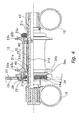
- the front hub 12 includes a hub shaft 31, a hub shell 32, a first spoke connector 33a, a second spoke connector 33b and a brake rotor mounting unit 34, as shown in Figure 4 .
- the hub shaft 31 rotatably supports the hub shell 32.
- the hub shaft 31 has a cylindrical central shaft member 31 a disposed in the center and first and second shaft members 31b and 31 c that contact the central shaft member 31a at either end thereof. These three components are cylindrical members having a center hole 31d through which a mounting bolt 41 passes in order to mount the front hub 12 to the suspension fork 15.
- the central shaft member 31a is disposed in the center of the hub shaft 31.
- the central shaft member 31a includes annular indentations 31e formed at each end. First and second O-rings 40 are mounted in the annular indentations 31 c to prevent vibration.
- the central shaft member 31 a is disposed so as to provide guidance during insertion of the mounting bolt 41.
- the hub shell 32 includes an internal pathway that extends between the first hub shell end 32a and the second hub shell end 32b, such that the hub shaft 31 is rotatably supported inside the internal pathway.
- the hub shell 32 further includes first and second spoke connectors 33a and 33b.
- the brake rotor mounting unit 34 and first and second spoke connectors 33a and 33b are integrally formed with the hub shell 32.
- the first spoke connector 33a and the brake rotor mounting unit 34 are integrally formed on the first hub shell end 32a
- the second spoke connector 33b is integrally formed on the second hub shell end 32b.
- the first spoke connector 33a is an annular spoke flange disposed on the first hub shell end 32a of the hub shell 32.
- the first spoke connector 33a includes multiple first spoke holes 43a.
- the first spoke holes 43a of this embodiment are arranged along the circumferential direction at equal intervals, for example, and are disposed such that they receive the bent ends of the spokes 24 (see Figure 1 ).
- the second hub shell end 32b of the hub shell 32 includes multiple second spoke holes 43b that receive the bent ends of the spokes 24.
- the second spoke holes 43b of this embodiment are disposed along the circumferential direction at equal intervals.
- Each spoke hole 43b is disposed such that it can receive a bent end of a spoke 24. Therefore, the front hub 12 is designed such that the spokes 24 extend toward the outer circumference of the front wheel 13.
- the disc brake rotor assembly 23 includes an annular rotor 26, an adapter 28 to which the rotor 26 is secured, and a tightening member 29 that non-rotatably secures the adapter 28 to the front hub 12.
- the rotor 26 and the adapter 28 are separated for ease of explanation, but in practice the rotor 26 is secured to the adapter 28 via a securing mechanism.
- the brake rotor mounting unit 34 is integrally formed with the first hub shell end 32a of the hub shell 32, as shown in Figures 4 through 6 .
- the brake rotor mounting unit 34 is disposed adjacent to the first spoke connector 3 3 a such that it faces the first hub shell end 32a.
- the brake rotor mounting unit 34 is a cylindrical unit that includes a cylindrical member 34a and an annular contact flange 34b that extends outward from the cylindrical member 34a.
- the annular contact flange 34b is disposed at a distance from the free end of the cylindrical member 34a.
- the cylindrical member 34a has an outer circumferential surface that includes outer circumferential splines 34c and an annular inner circumferential surface on which is formed an internal thread 34d.
- the outer circumferential splines 34c comprise protruding teeth disposed along the circumferential direction and engage non-rotatably with the disc brake rotor assembly 23.
- the tightening member 29 has an external thread 29e that engages the internal thread 34d. As a result, the tightening member 29 exerts pressure on the disc brake rotor assembly 23 in the direction of the annular contact flange 34b, and the disc brake rotor assembly 23 is non-rotatably secured to the brake rotor mounting unit 34 between the tightening member 29 and the annular contact flange 34b.
- the annular rotor 26 is non-rotatably mounted to the front hub 12 via the adapter 28.
- the adapter 28 links the rotor 26 and the front hub 12 such that they cannot rotate relative to each other.
- the tightening member 29 screws into the internal thread 34d formed in one end of the front hub 12, thereby securing to the front hub 12 the adapter 28 to which the rotor 26 is secured.
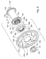
- the rotor 26 includes an annular brake ring 26a having braking surfaces 26e that are gripped by the caliper 21, multiple arms 26b that are integrally formed with the annular brake ring 26a, and an inner mounting area 26c that is integrally formed with the arms 26b.
- the rotor 26 is preferably an integrally-formed member obtained via press-forming of a metal plate.
- the annular brake ring 26a comprises the outer braking area of the rotor 26.
- the outer ends of the arms 26b are disposed in an equidistant fashion within the inner circumferential area of the annular brake ring 26a.
- the arms 26b comprise the central connecting area for the rotor 26, and extend between the annular brake ring 26a and the inner mounting area 26c.
- the arms 26b extend in a tangential fashion from the inner mounting area 26c such that triangular openings are formed between the adjacent arms 26b.
- the inner mounting area 26c has an annular configuration and has multiple inner circumferential splines 26d that have multiple notch-like indentations disposed at equal intervals on the inner circumferential surface of the inner mounting area 26c along the circumferential direction.
- the adapter 28 is a round cylindrical member that includes a cylindrical part 28a that is mounted to the brake rotor mounting unit 34 and a guard 28b that extends radially outward from one end of the cylindrical part 28a, as shown in Figures 5 and 6 .
- the adapter 28 further includes a force transmission mechanism such as multiple inner circumferential splines 28c or multiple outer circumferential splines 28d.
- Inner circumferential splines 28c are formed on the inner circumferential surface of the cylindrical part 28a and engage with the outer circumferential splines 34c.
- another rotation prevention mechanism such as the outer circumferential splines 28d are formed on the outer circumferential surface of the cylindrical part 28a and engage with the inner circumferential splines 26d of the rotor 26.
- the edge surface of the cylindrical part 28a of the adapter 28 is deformed in the outer circumferential direction via pressure exerted using a suitable jig to form a securing mechanism.
- the securing mechanism secures the rotor 26 is secured via crimping using a deformed area 28e.
- the adapter 28 be made of aluminum or other suitable material.
- the rotor 26 be made of stainless steel or other suitable material having a higher relative density than the first material used for the adapter 28.
- the tightening member 29 is a cylindrical member having a cylindrical part 29a, a guard 29b and external threads 29c.
- the cylindrical part 29a engages with the internal thread 34d formed in the inner circumferential surface of the cylindrical member 34a.
- the guard 29b extends radially outward from one end of the cylindrical part 29a.
- the external threads 29c engage with the internal threads 34d and are formed on the outer circumferential surface of the cylindrical part 29a.
- the guard 29b contacts the end surface of the cylindrical part 28a of the adapter 28 when the tightening member 29 is fully threaded into the internal thread 34d, thereby applying pressure on the adapter 28 in the direction of the annular contact flange 34b.
- the rotor 26 and the adapter 28 are non-rotatably secured to the brake rotor mounting unit 34.
- the rotor 26 Prior to mounting, the rotor 26 is secured to the adapter 28 via crimping.
- the adapter 28 is mounted to the rotor 26 by aligning the protrusions and indentations of the splines 28d and 26d. Pressure is then applied to the end surface of the cylindrical part 28a of the adapter 28 using a suitable crimping jig. A deformed area 28e that protrudes radially outward is then formed such that it contacts the inner mounting area 26c of the rotor 26. Securing the rotor 26 to the adapter 28 via crimping in this fashion enables the disk brake rotor assembly 23 to be easily attached or detached.
- the adapter 28, to which the rotor 26 is secured via crimping, is mounted to the brake rotor mounting unit 34 by aligning the splines 28c and 34c.
- the tightening member 29 is then mounted such that the adapter 28 sits between the annular contact flange 34b and the tightening member 29.
- the mounting of the tightening member 29 is carried out by screwing the external thread 29e of the tightening member 29 into the internal thread 34d formed in the brake rotor mounting unit 34 disposed at one end of the front hub 12. In this way, the disc brake rotor assembly 23 is non-rotatably secured to the brake rotor mounting unit 34a between the annular contact flange 34b and the tightening member 29.
- the rotor 26 is secured to the adapter via the deformation 28e formed through crimping and is prevented from rotating by the outer circumferential splines 28d and the inner circumferential splines 26d, the rotor 26 can be easily secured to the adapter 28 using the simple securing mechanism of deforming the adapter 28. Furthermore, the rotor 26 and the adapter 28 can be made of different materials, enabling the adapter 28 to be made lightweight. Furthermore, because the adapter 28 and the rotor 26 do not come apart when the adapter is detached from the front hub 12, the rotor 26 is less prone to deformation. In addition, because the disc brake rotor assembly 23 can be attached to or detached from the front hub 12 simply by attaching or detaching the adapter 28, the disc brake rotor assembly 23 can be attached or detached easily.
- the disc brake rotor assembly 23' differs from the assembly of the first embodiment in regard to the securing mechanism used for the rotor 26. That is, the adapter 28' is not deformed from crimping. Rather, in the second embodiment, the rotor 26 is secured to the adapter 28' via welding.
- the adapter 28' is identical to the adapter 28, except that the adapter 28' has been welded to the rotor 26 instead of being deformed to form the deformed area 28e.
- the adapter 28' is intended for welding and replaces the adapter 28 of the first embodiment that is intended for crimping.
- the rotor 26 and the adapter 28' are connected via welding beads 28f. Accordingly, the welding beads 28f form the securing mechanism in the second embodiment of the present invention. All other components of the disc brake rotor assembly 23' are identical to the disc brake rotor assembly 23 of the first embodiment.
- the rotor 26 is secured to the adapter via welding and is prevented from rotating by the splines 28d and a rotation prevention mechanism 26d.
- the rotor 26 can be secured to the adapter 28' by the simple securing mechanism of welding.
- the rotor 26 and the adapter 28' can be made of different materials, such that the adapter 28' can be made lightweight.
- the adapter 28' and the rotor 26 do not come apart when the adapter is detached from the front hub 12, the rotor 26 is less prone to deformation.
- the disc brake rotor assembly 23' can be attached to or detached from the front hub 12 simply by attaching or detaching the adapter 28', the disc brake rotor assembly 23' can be attached or detached easily.
- a disc brake rotor assembly 123 in accordance with a third embodiment will now be explained.
- the parts of the third embodiment that are identical to the parts of the prior embodiments will be given the same reference numerals as the parts of the prior embodiments.
- the descriptions of the parts of the third embodiment that are identical to the parts of the prior embodiments may be omitted for the sake of brevity.
- the securing mechanism for a rotor 126 of a disc brake rotor assembly 123 of a third embodiment is different from the securing mechanism used in the above embodiments.
- the adapter 128 is identical to the adapter 28, except that the splines 28d have been replaced with a plurality (eight) of bosses 128g and the adapter 128 has not be deformed to form the deformed area 28e.
- the (eight) bosses 128g are disposed on the outer surface of the guard 128b.
- the bosses 128g are round pillar-shaped protrusions disposed at equal spaced apart intervals along a circumferential direction of the adapter 128, while being parallel to the axis of rotation of the front hub 12.
- the bosses 128g are long enough to enable them to pass through the rotor 126.
- the rotor 126 is identical to the rotor 26, except that the notches 26d have been substituted with a plurality (eight) of through-holes 126f.
- the through-holes 126f are formed in the rotor 126 at equally spaced apart intervals along the circumferential direction so that the (eight) bosses 128g can pass therethrough.
- the tip of each boss 128g is deformed using a crimping tool so as to form a deformation 128e that widens around the periphery of the through-hole 126 so as to resemble the head of a round-head bolt.
- the rotor 126 and the adapter 128 of the disc brake assembly 123 are meant to replace the rotor 26 and the adapter 28 or 28' of the first and second embodiments. It will be apparent to one of skill in the art that the securing mechanisms of the first and second embodiments can be used in conjunction with the securing mechanism of the third embodiment.
- the rotor 126 is secured to the adapter 128 and prevented from rotating relative thereto by the (eight) bosses 128g disposed along the circumferential direction. Therefore, a rotation prevention mechanism, such as splines, need not be formed on the inner circumferential surface of the rotor 126 and the outer circumferential surface of the adapter 128. Furthermore, because the rotor 126 is secured to the adapter 128 and is prevented from rotating by the (eight) bosses 128g, the rotor 126 can be secured to the adapter 128 using a simple securing method such as crimping. As a result, the same effects as those obtained in the previous embodiments can be obtained.
- a disc brake rotor assembly 223 in accordance with a fourth embodiment will now be explained.
- the parts of the fourth embodiment that are identical to the parts of the prior embodiments will be given the same reference numerals as the parts of the prior embodiments.
- the descriptions of the parts of the fourth embodiment that are identical to the parts of the prior embodiments may be omitted for the sake of brevity.
- the disc brake rotor assembly 223 of the fourth embodiment differs from the third embodiment in regard to the securing mechanism for the rotor 226.
- the rotor 226 is secured to the adapter 228 by a plurality of rivets 230 that serve as securing members.
- the adapter 228 is identical to the adapter 28, except that the splines 28d have been replaced with a plurality (eight) of bosses 228g and the adapter 228 has not be deformed to form the deformed area 28e.
- the (eight) bosses 228g are disposed on the outer surface of the guard 228b.
- the bosses 228g are round pillar-shaped members disposed at equally spaced apart intervals along the circumferential direction and parallel to the rotational axis of the front hub 12.
- the rotor 226 is identical to the rotor 26, except that the notches 26d have been substituted with a plurality (eight) of through-holes 226f.
- the through-holes 226f are formed in the rotor 226 at equally spaced apart intervals along the circumferential direction so that the (eight) bosses 228g can pass therethrough.
- a crimping hole 228h is formed in the tip of each boss 228g.
- a rivet or rivet 230 having a round head 230a and a shaft 230b that extends from the center of the head 230a is pressed into each crimping hole 228h.
- the diameter of the shaft 230b of the rivet 230 is larger than the inner diameter of the crimping hole 228h, such that when the rivet 230 is pressed into the crimping hole 228h, the boss 228g widens and presses tightly against the walls of the through-hole 226f, thereby securing the rotor 226 to the adapter 228.
- the adapter 228 and the rotor 226 of the disc brake assembly 223 are meant to replace the adapter 128 and the rotor 126 of the third embodiment.
- the rivets 230 are used in place of the deformations 128e.
- the securing mechanisms of the first and second embodiments can be used in conjunction with the securing mechanism of the fourth embodiment.
- the rotor 226 is secured to the adapter 228 by the rivets 230, the rotor 226 can be reliably secured to the adapter 228 and a securing mechanism and rotation prevention mechanism can be obtained by the bosses 228g.
- a disc brake rotor assembly 323 in accordance with a fifth embodiment will now be explained.
- the parts of the fifth embodiment that are identical to the parts of the prior embodiments will be given the same reference numerals as the parts of the prior embodiments.
- the descriptions of the parts of the fifth embodiment that are identical to the parts of the prior embodiments may be omitted for the sake of brevity.
- the disc brake rotor assembly 323 of the fifth embodiment differs from the fourth embodiment in regard to the securing mechanism for the rotor 326, and the rotor 326 is secured to the adapter 328 by securing bolts 330 that serve as securing members.
- the adapter 328 is identical to the adapter 28, except that the splines 28d have been replaced with a plurality (eight) of bosses 328g and the adapter 328 has not be deformed to form the deformed area 28e.
- the (eight) bosses 328g are disposed on the outer surface of the guard 228b.
- the bosses 328g are round pillar-shaped members disposed at equal intervals along the circumferential direction and parallel to the rotational axis of the front hub 12.
- the bosses 328g are shorter than the thickness of the rotor 326.
- the rotor 326 is identical to the rotor 26, except that the notches 26d have been substituted with a plurality (eight) of through-holes 326f.
- the through-holes 326f are formed in the rotor 326 at equally spaced apart intervals along the circumferential direction so that the (eight) bosses 328g can pass therethrough.
- a screw hole 328h is formed in the tip of each boss 328g.
- a fixing bolt 330 having a round head 330a and a shaft 330b that extends from the center of the head 330a is screwed into the screw hole 328h.
- the head 330a exerts pressure on the rotor 236 toward the guard 328b, thereby securing the rotor 326 to the adapter 328.
- the adapter 328 and the rotor 326 of the disc brake assembly 323 are meant to replace the adapter 228 and the rotor 226 of the fourth embodiment.
- the fixing or securing bolts 330 are used in place of the rivets 230.
- the securing mechanisms of the first and second embodiments can be used in conjunction with the securing mechanism of the fifth embodiment.
- the rotor 326 is secured to the adapter 328 by the securing bolts 330, the rotor 326 can be reliably secured to the adapter 328 and a securing mechanism and rotation prevention mechanism can be obtained by the bosses 328g.
- a disc brake rotor assembly 423 in accordance with a sixth embodiment will now be explained.
- the parts of the sixth embodiment that are identical to the parts of the prior embodiments will be given the same reference numerals as the parts of the prior embodiments.
- the descriptions of the parts of the sixth embodiment that are identical to the parts of the prior embodiments may be omitted for the sake of brevity.
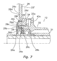
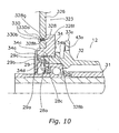
- the disc brake rotor assembly 423 of the sixth embodiment differs from the first through fifth embodiments described above in regard to the force transmission mechanism of the adapter 428.
- Force is transmitted from the adapter 428 to the front hub 412 via an internal thread 428c formed on the inner circumferential surface of the cylindrical part 428a of the adapter 428.
- the adapter 428 is identical to the adapter 28, except that the inner splines 28c have been replaced with internal thread 428c, the outer splines 28d have been replaced with a plurality (eight) of through-holes 428i, and the adapter 428 has not be deformed to form the deformed area 28e.
- the (eight) through-holes 428i are disposed on the outer surface of the guard 428b.
- the cylindrical part 434a of the brake rotor mounting unit 434 of the front hub 412 has an outer circumferential surface that includes an external thread 434c and an annular groove 434d formed in the external thread 434c.
- the external thread 434c engages with the internal thread 428c of the adapter 428 of the disc brake rotor assembly 423.
- An elastic stopper ring 429 that prevents the adapter 428 from becoming loose is mounted in the annular groove 434d.
- the annular groove 434d is formed such that the elastic stopper ring 429 comes into contact with the adapter 428 and is mounted at a distance from the contact surface of the annular contact flange 434b substantially equal to the thickness of the adapter 428.
- the sixth embodiment further differs from the first through fifth embodiments in regard to the securing mechanism.
- the rotor 426 is identical to the rotor 26, except that the notches 26d have been substituted with a plurality (eight) of through-holes 426f.
- the through-holes 426f are formed in the rotor 426 at equally spaced apart intervals along the circumferential direction so that (eight) rivets 430 can pass therethrough.
- the adapter 428 has the through-holes 428i disposed at equal intervals along the circumferential direction and parallel to the rotational axis of the front hub 412. Furthermore, the through-holes 426f and the through-holes 428i are configured and arranged to align with each other.
- One of the rivets 430 passes through each corresponding pair of holes 428i and 426f. Either end of the rivets 430 are deformed by having its diameter widened using a crimping tool such that it resembles the head of a round-head bolt.
- the adapter 428 and the rotor 426 of the disc brake assembly 423 are meant to replace the adapter 328 and the rotor 326 of the fifth embodiment.
- the rivets 430 are used in place of the fixing or securing bolts 330.
- the transmission mechanism of the sixth embodiment is meant to replace the transmission mechanism of the first through fifth embodiments.
- the tightening member 29 and the brake rotor mounting unit 34 of the first through fifth embodiments are replaced with the elastic stopper ring 429 and the brake rotor mounting unit 434 of the sixth embodiment.
- the rivets 430 were used as both the securing mechanism and the rotation prevention mechanism for the rotor 426 and the adapter 428.
- the construction for the securing mechanism and rotation mechanism used in the first through fifth embodiments can be used as well with this sixth embodiment.
- the force transmission mechanism has a simple construction. Because the mechanism to prevent loosening is achieved using the elastic stopper ring 429, the mechanism to prevent loosening is simpler as well.
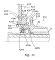
- a disc brake rotor assembly 523 in accordance with a seventh embodiment will now be explained.
- the parts of the seventh embodiment that are identical to the parts of the prior embodiments will be given the same reference numerals as the parts of the prior embodiments.
- the descriptions of the parts of the seventh embodiment that are identical to the parts of the prior embodiments may be omitted for the sake of brevity.
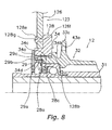
- the disc brake rotor assembly 523 of the seventh embodiment differs from the sixth embodiment described above in regard to the mechanism to prevent the adapter 528 from loosening, in that the tightening member 29 has the same construction as that used in the first through fifth embodiments. Therefore, an annular groove for mounting of an elastic stopper ring is not formed on the outer circumferential surface of the cylindrical part 534a of the brake rotor mounting unit 534 of the front hub 5. Rather, an internal thread 534d is formed on the inner circumferential surface of the cylindrical part 534a.
- the cylindrical part 534a of the brake rotor mounting unit 534 of the front hub 512 has an outer circumferential surface that includes an external thread 534c and an inner circumferential surface that includes an internal thread 534d.
- the adapter 528 is identical to the adapter 428.
- the adapter 528 is identical to the adapter 28,except that the inner splines 28c have been replaced with internal thread 528c, the outer splines 28d have been replaced with a plurality (eight) of through-holes 526g, and the adapter 528 has not be deformed to form the deformed area 28e.
- the (eight) through-holes 528i are disposed on the outer surface of the guard 528b.
- the external thread 534c engages with the internal thread 528c of the adapter 528 of the disc brake rotor assembly 523. Force is transmitted from the adapter 528 to the front hub 512 via an internal thread 528c formed on the internal circumferential surface of the cylindrical part 528a of the adapter 528.
- the internal thread 534d engages with the external thread 29e of the tightening member 29.
- the external thread 534c is a right-handed thread while the internal thread 534d is a left-handed thread. Therefore, when normal braking is carried out, the adapter 528 rotates in the direction of tightening relative to the front hub 512.
- the adapter 528 when braking on an uphill slope or backing up, the adapter 528 is less prone to becoming loose because the tightening member 29 rotates in the tightening direction relative to the adapter 528 even though the adapter 528 rotates in the loosening direction relative to the front hub 512.
- the rotor 526 is identical to the rotor 26, except that the notches 26d have been substituted with a plurality (eight) of through-holes 526f.
- the through-holes 526f are formed in the rotor 526 at equally spaced apart intervals along the circumferential direction so that (eight) rivets 530 can pass therethrough.
- the adapter 528 and the rotor 526 of the disc brake assembly 523 are meant to replace the adapter 428 and the rotor 426 of the sixth embodiment.
- the tightening member 29 has a construction identical to that of the corresponding member in the first though fifth embodiments.
- the right handed external threads 534c and the left handed internal threads 534d are used in place of the outer circumferential splines 34c and the inner circumferential splines 26c.
- the rivets 530 were used as the securing mechanism and the rotation prevention mechanism for the rotor 526 and the adapter 528.
- the construction for the securing mechanism and rotation mechanism used in the first through fifth embodiments can be used as well with the seventh embodiment.
Landscapes
- Engineering & Computer Science (AREA)
- Mechanical Engineering (AREA)
- Braking Arrangements (AREA)
Claims (12)
- Ensemble de rotor de frein à disque de bicyclette (23, 123, 223, 323, 423, 523) comprenant :un rotor en forme d'anneau (26, 126, 226, 326, 426, 526) ayant une paire de pistes de freinage (26e) devant être saisies par un étrier (21), etun adaptateur (28, 28', 128, 228, 328, 428, 528) incluant un mécanisme de fixation configuré pour y fixer le rotor, et un mécanisme empêchant une rotation (28g, 128g, 228g, 328g) formé entre la surface extérieure de l'adaptateur (28, 28', 128, 228, 328, 428, 528) et le rotor (26, 126, 226, 326, 426, 526) pour empêcher la rotation du rotor par rapport à l'adaptateur (28, 28', 128, 228, 328, 428, 528) ; etcaractérisé en ce que l'adaptateur (28, 28', 128, 228, 328, 428, 528) comprend en outre un mécanisme interne de transmission de force configuré pour transmettre la force de freinage exercée sur le rotor (26, 126, 226, 326, 426, 526) à une surface périphérique extérieure d'un moyeu (12).
- Ensemble de rotor de frein à disque de bicyclette (23, 123, 223, 323, 423, 523) selon la revendication 1, dans lequel
le mécanisme interne de transmission de force comprend un premier filetage intérieur (428c, 528c) configuré pour coopérer avec un premier filetage extérieur (434c) formé sur la surface périphérique extérieure du moyeu (412, 512). - Ensemble de rotor de frein à disque de bicyclette (23, 123, 223, 323, 423, 523) selon la revendication 2, comprenant en outre
une rondelle d'arrêt (429) configurée pour être montée dans une rainure annulaire (434d) formée dans le premier filetage extérieur (434c) du moyeu (12, 412) afin d'empêcher l'adaptateur (28, 428) de se desserrer. - Ensemble de rotor de frein à disque de bicyclette (23, 123, 223, 323) selon la revendication 1, dans lequel
le mécanisme interne de transmission de force comprend des cannelures (28c) qui s'apparient de manière non rotative avec la surface périphérique extérieure du moyeu (12). - Ensemble de rotor de frein à disque de bicyclette (23, 123, 223, 323, 423, 523) selon la revendication 2, comprenant en outre
un élément de serrage (29) comprenant un deuxième filetage extérieur (29c) configuré pour coopérer avec le moyeu (12) de bicyclette afin d'empêcher l'adaptateur (28) de se desserrer. - Ensemble de rotor de frein à disque de bicyclette (23, 123, 223, 323, 423, 523) selon la revendication 5, dans lequel
le deuxième filetage extérieur (29c) passe dans une direction opposée à celle du premier filetage intérieur (428c). - Ensemble de rotor de frein à disque de bicyclette (423, 523) selon la revendication 2, dans lequel
le mécanisme de fixation de l'adaptateur (428, 528) comprend des rivets (430, 530) qui couplent le rotor (426, 526) à l'adaptateur (428, 528). - Ensemble de rotor de frein à disque de bicyclette (23) selon la revendication 1, dans lequel
le mécanisme de fixation de l'adaptateur (28) comprend un sertissage (28e) qui déforme l'adaptateur (28). - Ensemble de rotor de frein à disque de bicyclette (23) selon la revendication 1, dans lequel
le mécanisme de fixation de l'adaptateur (28') comprend une soudure (28f). - Ensemble de rotor de frein à disque de bicyclette (23, 123, 223, 323, 423, 523) selon la revendication 1, dans lequel l'adaptateur (28, 228, 328) comprend une pluralité de bossages extérieurs (128g, 228g, 328g) disposés à des intervalles égaux dans une direction périphérique de l'adaptateur (28) pour fixer de manière non rotative le rotor (26) sur l'adaptateur (28).
- Ensemble de rotor de frein à disque de bicyclette (123, 223, 323) selon la revendication 10, dans lequel
chacun des bossages (128g, 228g) comprend un trou (228h) formé dans une extrémité de chacun des bossages (128g, 228g) avec des éléments de fixation (230, 330) fixés dans les trous pour fixer le rotor (126, 226, 326) sur l'adaptateur (128, 228, 328). - Ensemble de rotor de frein à disque de bicyclette (123, 223, 323) selon la revendication 10, dans lequel
le rotor (126) est fixé sur l'adaptateur (128) par l'intermédiaire d'un sertissage (128e) qui déforme une extrémité de chacun des bossages (128g).
Applications Claiming Priority (2)
| Application Number | Priority Date | Filing Date | Title |
|---|---|---|---|
| JP2004124395 | 2004-04-20 | ||
| JP2004124395A JP2005308059A (ja) | 2004-04-20 | 2004-04-20 | 自転車用ディスクブレーキロータ組立体 |
Publications (2)
| Publication Number | Publication Date |
|---|---|
| EP1588932A1 EP1588932A1 (fr) | 2005-10-26 |
| EP1588932B1 true EP1588932B1 (fr) | 2009-07-08 |
Family
ID=34935373
Family Applications (1)
| Application Number | Title | Priority Date | Filing Date |
|---|---|---|---|
| EP05008509A Expired - Lifetime EP1588932B1 (fr) | 2004-04-20 | 2005-04-19 | Ensemble de rotor de frein à disque pour une bicyclette |
Country Status (7)
| Country | Link |
|---|---|
| US (1) | US7216743B2 (fr) |
| EP (1) | EP1588932B1 (fr) |
| JP (1) | JP2005308059A (fr) |
| CN (1) | CN100453399C (fr) |
| AT (1) | ATE435806T1 (fr) |
| DE (1) | DE602005015271D1 (fr) |
| TW (1) | TWI276567B (fr) |
Cited By (1)
| Publication number | Priority date | Publication date | Assignee | Title |
|---|---|---|---|---|
| EP3441235B1 (fr) * | 2017-08-08 | 2022-06-15 | Campagnolo S.r.l. | Moyeu de roue de bicyclette et son ensemble de moyeu |
Families Citing this family (34)
| Publication number | Priority date | Publication date | Assignee | Title |
|---|---|---|---|---|
| US6371252B1 (en) * | 2001-08-30 | 2002-04-16 | Shimano Inc. | Bicycle disc brake hub |
| US20060081425A1 (en) * | 2004-10-15 | 2006-04-20 | Hubert Chen | Brake disk and a brakable wheel hub device having the same |
| US20060238019A1 (en) * | 2005-04-21 | 2006-10-26 | Mark Yu | Brakable wheel hub device |
| EP1963713B1 (fr) * | 2005-12-09 | 2015-02-25 | Fallbrook Intellectual Property Company LLC | Transmission a variation continue |
| US7367632B2 (en) * | 2005-12-14 | 2008-05-06 | Ming Cycle Industrial Co., Ltd. | Hub assembly for disk brake of bicycle |
| JP4610532B2 (ja) * | 2006-02-17 | 2011-01-12 | 株式会社シマノ | 自転車用ディスクブレーキハブ |
| ES2379588T3 (es) * | 2006-09-14 | 2012-04-27 | Otis Elevator Company, A New Jersey Corporation | Freno de ascensor con buje de freno compuesto |
| JP4754543B2 (ja) * | 2007-11-08 | 2011-08-24 | 曙ブレーキ工業株式会社 | 多板式ディスクブレーキ装置、及びその組立方法 |
| US7695073B1 (en) * | 2007-11-29 | 2010-04-13 | Chosen Co., Ltd. | Bicycle rear hub that is especially available for acrobatics |
| US20110193403A1 (en) * | 2010-02-11 | 2011-08-11 | Wu-Hui Chen | Bicycle Spoke and Hub Assembly |
| TWI408061B (zh) * | 2010-02-11 | 2013-09-11 | Gigantex Composite Technologies Co Ltd | A combination of radiant and hubs |
| DE102010035492A1 (de) * | 2010-08-26 | 2012-03-01 | Gustav Magenwirth Gmbh & Co. Kg | Hydraulische Scheibenbremse |
| EP2698311A3 (fr) * | 2010-08-26 | 2014-05-07 | Gustav Magenwirth GmbH & Co. KG | Frein à disque hydraulique |
| DE102010040045A1 (de) * | 2010-08-31 | 2012-03-01 | Gustav Magenwirth Gmbh & Co. Kg | Geberarmatur und hydraulische Scheibenbremse |
| US8186698B2 (en) * | 2010-10-27 | 2012-05-29 | Gunderson Mark E | Tricycle |
| FR2973462A1 (fr) * | 2011-04-04 | 2012-10-05 | Bosch Gmbh Robert | Capuchon de piston de frein a disque et frein a disque ainsi equipe |
| US10189305B2 (en) * | 2011-08-29 | 2019-01-29 | Sram, Llc | Bicycle front wheel hub with torque tube |
| RU2508219C1 (ru) * | 2012-10-24 | 2014-02-27 | Общество с ограниченной ответственностью "Трейд-Импорт" | Дисковое велосипедное тормозное устройство |
| US9878577B2 (en) * | 2013-09-12 | 2018-01-30 | Walther Engineering And Manufacturing Company, Inc. | Hub-rotor adapter |
| CN203996714U (zh) * | 2013-10-09 | 2014-12-10 | 黄国政 | 一种用于机械碟刹的双轴转子装置 |
| CN103953670B (zh) * | 2014-05-04 | 2016-09-07 | 宏展五金塑胶制品(苏州)有限公司 | 自行车盘式制动器 |
| CN103950500B (zh) * | 2014-05-04 | 2017-06-30 | 宏展五金塑胶制品(苏州)有限公司 | 一种自行车盘式制动器 |
| CN104260813A (zh) * | 2014-09-23 | 2015-01-07 | 宏展五金塑胶制品(苏州)有限公司 | 一种自行车盘式制动器用的安全轴套及自行车盘式制动器 |
| DE102014117145A1 (de) * | 2014-11-24 | 2016-05-25 | Dt Swiss Ag | Fahrradkomponente mit einem Endanschlag und Endanschlag |
| CN104512197B (zh) * | 2014-12-18 | 2017-06-09 | 余迪青 | 自行车花毂装置 |
| US10480601B2 (en) | 2016-06-22 | 2019-11-19 | Sram, Llc | Heat dissipating brake rotor |
| DE102016111942A1 (de) | 2016-06-30 | 2018-01-04 | Knorr-Bremse Systeme für Nutzfahrzeuge GmbH | Achsenend-Baugruppe mit einer Radnabeneinheit und einer Radbremse |
| IT201600069575A1 (it) | 2016-07-05 | 2018-01-05 | Campagnolo Srl | Disco freno per bicicletta |
| IT201600069580A1 (it) * | 2016-07-05 | 2018-01-05 | Campagnolo Srl | Disco freno per bicicletta |
| CN106043575A (zh) * | 2016-07-12 | 2016-10-26 | 温芫鋐 | 碟盘保护盖 |
| CN108297846B (zh) | 2017-01-13 | 2024-01-12 | 株式会社岛野 | 盘式制动器转子的适配器、包括该适配器的盘式制动器转子及磁发生装置 |
| IT201700046888A1 (it) * | 2017-05-02 | 2018-11-02 | Campagnolo Srl | Assieme di disco freno per bicicletta |
| US10919339B2 (en) * | 2017-05-22 | 2021-02-16 | Shimano Inc. | Bicycle hub assembly and bicycle drive train assembly |
| CN110778630A (zh) * | 2019-09-28 | 2020-02-11 | 徐州顺达钢轮制造有限公司 | 一种便于拆卸的刹车片 |
Family Cites Families (12)
| Publication number | Priority date | Publication date | Assignee | Title |
|---|---|---|---|---|
| IT1284314B1 (it) | 1996-01-11 | 1998-05-18 | Skf Ind Spa | Gruppo cuscinetto per mozzo ruota di veicolo. |
| IT1285868B1 (it) * | 1996-05-10 | 1998-06-24 | Skf Ind Spa | Gruppo cuscinetto/organo frenante perfezionato per autotrazione, provvisto di un elemento di collegamento intermedio tra cuscinetto ed |
| IT1305623B1 (it) * | 1998-05-05 | 2001-05-09 | Rivolta S P A | Impianto frenante per bicicletta |
| FR2799520B1 (fr) * | 1999-10-08 | 2002-01-25 | Messier Bugatti | Dispositif de fixaion axiale d'un disque ventile de freinage sur le moyeu d'une roue d'un vehicule automobile |
| FR2810382B1 (fr) | 2000-06-16 | 2002-08-30 | Peugeot Citroen Automobiles Sa | Dispositif d'assemblage d'un element rotatif d'un mecanisme de frein avec un moyen de roue de vehicule |
| DE10104256A1 (de) | 2001-01-31 | 2002-08-29 | Magenwirth Gmbh Co Gustav | Bremssystem |
| US6540306B2 (en) * | 2001-06-29 | 2003-04-01 | Shimano Inc. | Bicycle disc brake hub |
| US6371252B1 (en) * | 2001-08-30 | 2002-04-16 | Shimano Inc. | Bicycle disc brake hub |
| CA2415809A1 (fr) * | 2002-01-09 | 2003-07-09 | First Principles Engineering Inc. | Adaptateur de moyeu pour frein a disque de bicyclette |
| JP3732166B2 (ja) * | 2002-08-22 | 2006-01-05 | 株式会社シマノ | 自転車用ハブ |
| US6854569B2 (en) * | 2003-03-18 | 2005-02-15 | Kun Teng Industry Co., Ltd. | Brakable wheel hub device |
| WO2004088162A1 (fr) | 2003-03-28 | 2004-10-14 | Hayes Disc Brakes, Llc | Rotor de frein a disque a montage rapide |
-
2004
- 2004-04-20 JP JP2004124395A patent/JP2005308059A/ja not_active Withdrawn
-
2005
- 2005-03-01 TW TW094106155A patent/TWI276567B/zh not_active IP Right Cessation
- 2005-04-05 US US11/098,568 patent/US7216743B2/en not_active Expired - Fee Related
- 2005-04-19 AT AT05008509T patent/ATE435806T1/de not_active IP Right Cessation
- 2005-04-19 DE DE602005015271T patent/DE602005015271D1/de not_active Expired - Lifetime
- 2005-04-19 EP EP05008509A patent/EP1588932B1/fr not_active Expired - Lifetime
- 2005-04-20 CN CNB2005100669435A patent/CN100453399C/zh not_active Expired - Fee Related
Cited By (1)
| Publication number | Priority date | Publication date | Assignee | Title |
|---|---|---|---|---|
| EP3441235B1 (fr) * | 2017-08-08 | 2022-06-15 | Campagnolo S.r.l. | Moyeu de roue de bicyclette et son ensemble de moyeu |
Also Published As
| Publication number | Publication date |
|---|---|
| US20050230199A1 (en) | 2005-10-20 |
| CN1689899A (zh) | 2005-11-02 |
| TWI276567B (en) | 2007-03-21 |
| DE602005015271D1 (de) | 2009-08-20 |
| CN100453399C (zh) | 2009-01-21 |
| TW200538348A (en) | 2005-12-01 |
| ATE435806T1 (de) | 2009-07-15 |
| JP2005308059A (ja) | 2005-11-04 |
| EP1588932A1 (fr) | 2005-10-26 |
| US7216743B2 (en) | 2007-05-15 |
Similar Documents
| Publication | Publication Date | Title |
|---|---|---|
| EP1588932B1 (fr) | Ensemble de rotor de frein à disque pour une bicyclette | |
| EP1288117B2 (fr) | Moyeu pour frein à disque de bicyclette | |
| TWI259878B (en) | Disk brake rotor assembly | |
| EP1413506B1 (fr) | Ensemble moyeu essieu pour bicyclette | |
| US7143872B2 (en) | Apparatus for retaining a bicycle disk brake rotor to a bicycle wheel hub | |
| US6880897B2 (en) | Hub adapter for a bicycle disc brake | |
| US11274717B2 (en) | Brake rotor assembly | |
| EP1847452B1 (fr) | Dispositif de fixation d'un rotor d'un frein à disque | |
| US8292046B2 (en) | Wheel carrier for vehicles with a disc brake | |
| JP3703781B2 (ja) | 自転車用ディスクブレーキハブ | |
| US6974275B2 (en) | Locking member for bicycle component | |
| JP2001213107A (ja) | タンジェントスポーク用自転車ハブ | |
| US6485108B1 (en) | Bicycle hub | |
| GB2189576A (en) | Coupling asembly for a wheel and axle | |
| CN116323381A (zh) | 将驱动单元连接到车轮的连接装置 | |
| GB2165497A (en) | Motor cycle wheel assembly |
Legal Events
| Date | Code | Title | Description |
|---|---|---|---|
| PUAI | Public reference made under article 153(3) epc to a published international application that has entered the european phase |
Free format text: ORIGINAL CODE: 0009012 |
|
| 17P | Request for examination filed |
Effective date: 20050712 |
|
| AK | Designated contracting states |
Kind code of ref document: A1 Designated state(s): AT BE BG CH CY CZ DE DK EE ES FI FR GB GR HU IE IS IT LI LT LU MC NL PL PT RO SE SI SK TR |
|
| AX | Request for extension of the european patent |
Extension state: AL BA HR LV MK YU |
|
| AKX | Designation fees paid |
Designated state(s): AT BE BG CH CY CZ DE DK EE ES FI FR GB GR HU IE IS IT LI LT LU MC NL PL PT RO SE SI SK TR |
|
| RAP1 | Party data changed (applicant data changed or rights of an application transferred) |
Owner name: SHIMANO INC. |
|
| 17Q | First examination report despatched |
Effective date: 20060725 |
|
| GRAP | Despatch of communication of intention to grant a patent |
Free format text: ORIGINAL CODE: EPIDOSNIGR1 |
|
| GRAS | Grant fee paid |
Free format text: ORIGINAL CODE: EPIDOSNIGR3 |
|
| GRAA | (expected) grant |
Free format text: ORIGINAL CODE: 0009210 |
|
| AK | Designated contracting states |
Kind code of ref document: B1 Designated state(s): AT BE BG CH CY CZ DE DK EE ES FI FR GB GR HU IE IS IT LI LT LU MC NL PL PT RO SE SI SK TR |
|
| REG | Reference to a national code |
Ref country code: GB Ref legal event code: FG4D |
|
| REG | Reference to a national code |
Ref country code: CH Ref legal event code: EP |
|
| REG | Reference to a national code |
Ref country code: IE Ref legal event code: FG4D |
|
| REF | Corresponds to: |
Ref document number: 602005015271 Country of ref document: DE Date of ref document: 20090820 Kind code of ref document: P |
|
| PG25 | Lapsed in a contracting state [announced via postgrant information from national office to epo] |
Ref country code: SI Free format text: LAPSE BECAUSE OF FAILURE TO SUBMIT A TRANSLATION OF THE DESCRIPTION OR TO PAY THE FEE WITHIN THE PRESCRIBED TIME-LIMIT Effective date: 20090708 |
|
| NLV1 | Nl: lapsed or annulled due to failure to fulfill the requirements of art. 29p and 29m of the patents act | ||
| PG25 | Lapsed in a contracting state [announced via postgrant information from national office to epo] |
Ref country code: LT Free format text: LAPSE BECAUSE OF FAILURE TO SUBMIT A TRANSLATION OF THE DESCRIPTION OR TO PAY THE FEE WITHIN THE PRESCRIBED TIME-LIMIT Effective date: 20090708 Ref country code: IS Free format text: LAPSE BECAUSE OF FAILURE TO SUBMIT A TRANSLATION OF THE DESCRIPTION OR TO PAY THE FEE WITHIN THE PRESCRIBED TIME-LIMIT Effective date: 20091108 Ref country code: FI Free format text: LAPSE BECAUSE OF FAILURE TO SUBMIT A TRANSLATION OF THE DESCRIPTION OR TO PAY THE FEE WITHIN THE PRESCRIBED TIME-LIMIT Effective date: 20090708 Ref country code: ES Free format text: LAPSE BECAUSE OF FAILURE TO SUBMIT A TRANSLATION OF THE DESCRIPTION OR TO PAY THE FEE WITHIN THE PRESCRIBED TIME-LIMIT Effective date: 20091019 Ref country code: AT Free format text: LAPSE BECAUSE OF FAILURE TO SUBMIT A TRANSLATION OF THE DESCRIPTION OR TO PAY THE FEE WITHIN THE PRESCRIBED TIME-LIMIT Effective date: 20090708 |
|
| PG25 | Lapsed in a contracting state [announced via postgrant information from national office to epo] |
Ref country code: PL Free format text: LAPSE BECAUSE OF FAILURE TO SUBMIT A TRANSLATION OF THE DESCRIPTION OR TO PAY THE FEE WITHIN THE PRESCRIBED TIME-LIMIT Effective date: 20090708 Ref country code: NL Free format text: LAPSE BECAUSE OF FAILURE TO SUBMIT A TRANSLATION OF THE DESCRIPTION OR TO PAY THE FEE WITHIN THE PRESCRIBED TIME-LIMIT Effective date: 20090708 |
|
| PG25 | Lapsed in a contracting state [announced via postgrant information from national office to epo] |
Ref country code: PT Free format text: LAPSE BECAUSE OF FAILURE TO SUBMIT A TRANSLATION OF THE DESCRIPTION OR TO PAY THE FEE WITHIN THE PRESCRIBED TIME-LIMIT Effective date: 20091109 Ref country code: BG Free format text: LAPSE BECAUSE OF FAILURE TO SUBMIT A TRANSLATION OF THE DESCRIPTION OR TO PAY THE FEE WITHIN THE PRESCRIBED TIME-LIMIT Effective date: 20091008 |
|
| PG25 | Lapsed in a contracting state [announced via postgrant information from national office to epo] |
Ref country code: EE Free format text: LAPSE BECAUSE OF FAILURE TO SUBMIT A TRANSLATION OF THE DESCRIPTION OR TO PAY THE FEE WITHIN THE PRESCRIBED TIME-LIMIT Effective date: 20090708 Ref country code: DK Free format text: LAPSE BECAUSE OF FAILURE TO SUBMIT A TRANSLATION OF THE DESCRIPTION OR TO PAY THE FEE WITHIN THE PRESCRIBED TIME-LIMIT Effective date: 20090708 Ref country code: RO Free format text: LAPSE BECAUSE OF FAILURE TO SUBMIT A TRANSLATION OF THE DESCRIPTION OR TO PAY THE FEE WITHIN THE PRESCRIBED TIME-LIMIT Effective date: 20090708 Ref country code: CZ Free format text: LAPSE BECAUSE OF FAILURE TO SUBMIT A TRANSLATION OF THE DESCRIPTION OR TO PAY THE FEE WITHIN THE PRESCRIBED TIME-LIMIT Effective date: 20090708 |
|
| PLBE | No opposition filed within time limit |
Free format text: ORIGINAL CODE: 0009261 |
|
| STAA | Information on the status of an ep patent application or granted ep patent |
Free format text: STATUS: NO OPPOSITION FILED WITHIN TIME LIMIT |
|
| PG25 | Lapsed in a contracting state [announced via postgrant information from national office to epo] |
Ref country code: SK Free format text: LAPSE BECAUSE OF FAILURE TO SUBMIT A TRANSLATION OF THE DESCRIPTION OR TO PAY THE FEE WITHIN THE PRESCRIBED TIME-LIMIT Effective date: 20090708 Ref country code: BE Free format text: LAPSE BECAUSE OF FAILURE TO SUBMIT A TRANSLATION OF THE DESCRIPTION OR TO PAY THE FEE WITHIN THE PRESCRIBED TIME-LIMIT Effective date: 20090708 |
|
| 26N | No opposition filed |
Effective date: 20100409 |
|
| PG25 | Lapsed in a contracting state [announced via postgrant information from national office to epo] |
Ref country code: GR Free format text: LAPSE BECAUSE OF FAILURE TO SUBMIT A TRANSLATION OF THE DESCRIPTION OR TO PAY THE FEE WITHIN THE PRESCRIBED TIME-LIMIT Effective date: 20091009 |
|
| PG25 | Lapsed in a contracting state [announced via postgrant information from national office to epo] |
Ref country code: MC Free format text: LAPSE BECAUSE OF NON-PAYMENT OF DUE FEES Effective date: 20100430 |
|
| REG | Reference to a national code |
Ref country code: CH Ref legal event code: PL |
|
| GBPC | Gb: european patent ceased through non-payment of renewal fee |
Effective date: 20100419 |
|
| REG | Reference to a national code |
Ref country code: FR Ref legal event code: ST Effective date: 20101230 |
|
| PG25 | Lapsed in a contracting state [announced via postgrant information from national office to epo] |
Ref country code: IE Free format text: LAPSE BECAUSE OF NON-PAYMENT OF DUE FEES Effective date: 20100419 |
|
| PG25 | Lapsed in a contracting state [announced via postgrant information from national office to epo] |
Ref country code: CH Free format text: LAPSE BECAUSE OF NON-PAYMENT OF DUE FEES Effective date: 20100430 Ref country code: LI Free format text: LAPSE BECAUSE OF NON-PAYMENT OF DUE FEES Effective date: 20100430 |
|
| PG25 | Lapsed in a contracting state [announced via postgrant information from national office to epo] |
Ref country code: IT Free format text: LAPSE BECAUSE OF FAILURE TO SUBMIT A TRANSLATION OF THE DESCRIPTION OR TO PAY THE FEE WITHIN THE PRESCRIBED TIME-LIMIT Effective date: 20090708 Ref country code: GB Free format text: LAPSE BECAUSE OF NON-PAYMENT OF DUE FEES Effective date: 20100419 |
|
| PG25 | Lapsed in a contracting state [announced via postgrant information from national office to epo] |
Ref country code: FR Free format text: LAPSE BECAUSE OF NON-PAYMENT OF DUE FEES Effective date: 20100430 |
|
| PG25 | Lapsed in a contracting state [announced via postgrant information from national office to epo] |
Ref country code: CY Free format text: LAPSE BECAUSE OF FAILURE TO SUBMIT A TRANSLATION OF THE DESCRIPTION OR TO PAY THE FEE WITHIN THE PRESCRIBED TIME-LIMIT Effective date: 20090708 |
|
| PG25 | Lapsed in a contracting state [announced via postgrant information from national office to epo] |
Ref country code: LU Free format text: LAPSE BECAUSE OF NON-PAYMENT OF DUE FEES Effective date: 20100419 Ref country code: HU Free format text: LAPSE BECAUSE OF FAILURE TO SUBMIT A TRANSLATION OF THE DESCRIPTION OR TO PAY THE FEE WITHIN THE PRESCRIBED TIME-LIMIT Effective date: 20100109 Ref country code: SE Free format text: LAPSE BECAUSE OF FAILURE TO SUBMIT A TRANSLATION OF THE DESCRIPTION OR TO PAY THE FEE WITHIN THE PRESCRIBED TIME-LIMIT Effective date: 20090708 |
|
| PG25 | Lapsed in a contracting state [announced via postgrant information from national office to epo] |
Ref country code: TR Free format text: LAPSE BECAUSE OF FAILURE TO SUBMIT A TRANSLATION OF THE DESCRIPTION OR TO PAY THE FEE WITHIN THE PRESCRIBED TIME-LIMIT Effective date: 20090708 |
|
| PGFP | Annual fee paid to national office [announced via postgrant information from national office to epo] |
Ref country code: DE Payment date: 20150414 Year of fee payment: 11 |
|
| REG | Reference to a national code |
Ref country code: DE Ref legal event code: R119 Ref document number: 602005015271 Country of ref document: DE |
|
| PG25 | Lapsed in a contracting state [announced via postgrant information from national office to epo] |
Ref country code: DE Free format text: LAPSE BECAUSE OF NON-PAYMENT OF DUE FEES Effective date: 20161101 |