EP1588844B1 - Composite material with impact absorbing layer - Google Patents
Composite material with impact absorbing layer Download PDFInfo
- Publication number
- EP1588844B1 EP1588844B1 EP05008723A EP05008723A EP1588844B1 EP 1588844 B1 EP1588844 B1 EP 1588844B1 EP 05008723 A EP05008723 A EP 05008723A EP 05008723 A EP05008723 A EP 05008723A EP 1588844 B1 EP1588844 B1 EP 1588844B1
- Authority
- EP
- European Patent Office
- Prior art keywords
- layer
- plastic
- composite
- layers
- plastic material
- Prior art date
- Legal status (The legal status is an assumption and is not a legal conclusion. Google has not performed a legal analysis and makes no representation as to the accuracy of the status listed.)
- Active
Links
- 239000002131 composite material Substances 0.000 title claims abstract description 102
- 229920003023 plastic Polymers 0.000 claims abstract description 124
- 239000004033 plastic Substances 0.000 claims abstract description 124
- 239000000463 material Substances 0.000 claims abstract description 26
- 238000004519 manufacturing process Methods 0.000 claims abstract description 23
- 230000001681 protective effect Effects 0.000 claims abstract description 18
- 238000000034 method Methods 0.000 claims abstract description 15
- 239000006260 foam Substances 0.000 claims abstract description 8
- 229920001684 low density polyethylene Polymers 0.000 claims description 8
- 239000004702 low-density polyethylene Substances 0.000 claims description 8
- 239000004743 Polypropylene Substances 0.000 claims description 7
- -1 polypropylene Polymers 0.000 claims description 7
- 229920001155 polypropylene Polymers 0.000 claims description 7
- 229920001179 medium density polyethylene Polymers 0.000 claims description 3
- 239000004701 medium-density polyethylene Substances 0.000 claims description 3
- 239000000155 melt Substances 0.000 claims description 3
- 229920000098 polyolefin Polymers 0.000 claims description 3
- BLDFSDCBQJUWFG-UHFFFAOYSA-N 2-(methylamino)-1,2-diphenylethanol Chemical compound C=1C=CC=CC=1C(NC)C(O)C1=CC=CC=C1 BLDFSDCBQJUWFG-UHFFFAOYSA-N 0.000 claims description 2
- 238000003466 welding Methods 0.000 claims description 2
- VGGSQFUCUMXWEO-UHFFFAOYSA-N Ethene Chemical compound C=C VGGSQFUCUMXWEO-UHFFFAOYSA-N 0.000 claims 3
- 238000012856 packing Methods 0.000 claims 2
- 230000006978 adaptation Effects 0.000 claims 1
- 230000015572 biosynthetic process Effects 0.000 claims 1
- 238000001125 extrusion Methods 0.000 claims 1
- 230000007797 corrosion Effects 0.000 abstract description 12
- 238000005260 corrosion Methods 0.000 abstract description 12
- 238000004806 packaging method and process Methods 0.000 abstract description 12
- 239000000654 additive Substances 0.000 abstract description 10
- 230000000996 additive effect Effects 0.000 abstract description 7
- 230000008018 melting Effects 0.000 abstract description 3
- 238000002844 melting Methods 0.000 abstract description 3
- 239000010410 layer Substances 0.000 description 152
- 239000004698 Polyethylene Substances 0.000 description 8
- 230000002401 inhibitory effect Effects 0.000 description 7
- SHAHPWSYJFYMRX-GDLCADMTSA-N (2S)-2-(4-{[(1R,2S)-2-hydroxycyclopentyl]methyl}phenyl)propanoic acid Chemical compound C1=CC([C@@H](C(O)=O)C)=CC=C1C[C@@H]1[C@@H](O)CCC1 SHAHPWSYJFYMRX-GDLCADMTSA-N 0.000 description 5
- 150000001875 compounds Chemical class 0.000 description 4
- 230000000694 effects Effects 0.000 description 4
- 230000009969 flowable effect Effects 0.000 description 3
- 239000004615 ingredient Substances 0.000 description 3
- 229920000573 polyethylene Polymers 0.000 description 3
- VTYYLEPIZMXCLO-UHFFFAOYSA-L Calcium carbonate Chemical group [Ca+2].[O-]C([O-])=O VTYYLEPIZMXCLO-UHFFFAOYSA-L 0.000 description 2
- 239000004952 Polyamide Substances 0.000 description 2
- 229910052751 metal Inorganic materials 0.000 description 2
- 239000002184 metal Substances 0.000 description 2
- 239000000203 mixture Substances 0.000 description 2
- 239000004745 nonwoven fabric Substances 0.000 description 2
- 229920002647 polyamide Polymers 0.000 description 2
- 238000004804 winding Methods 0.000 description 2
- UNILWMWFPHPYOR-KXEYIPSPSA-M 1-[6-[2-[3-[3-[3-[2-[2-[3-[[2-[2-[[(2r)-1-[[2-[[(2r)-1-[3-[2-[2-[3-[[2-(2-amino-2-oxoethoxy)acetyl]amino]propoxy]ethoxy]ethoxy]propylamino]-3-hydroxy-1-oxopropan-2-yl]amino]-2-oxoethyl]amino]-3-[(2r)-2,3-di(hexadecanoyloxy)propyl]sulfanyl-1-oxopropan-2-yl Chemical compound O=C1C(SCCC(=O)NCCCOCCOCCOCCCNC(=O)COCC(=O)N[C@@H](CSC[C@@H](COC(=O)CCCCCCCCCCCCCCC)OC(=O)CCCCCCCCCCCCCCC)C(=O)NCC(=O)N[C@H](CO)C(=O)NCCCOCCOCCOCCCNC(=O)COCC(N)=O)CC(=O)N1CCNC(=O)CCCCCN\1C2=CC=C(S([O-])(=O)=O)C=C2CC/1=C/C=C/C=C/C1=[N+](CC)C2=CC=C(S([O-])(=O)=O)C=C2C1 UNILWMWFPHPYOR-KXEYIPSPSA-M 0.000 description 1
- 239000012790 adhesive layer Substances 0.000 description 1
- 229910052782 aluminium Inorganic materials 0.000 description 1
- XAGFODPZIPBFFR-UHFFFAOYSA-N aluminium Chemical compound [Al] XAGFODPZIPBFFR-UHFFFAOYSA-N 0.000 description 1
- 230000004888 barrier function Effects 0.000 description 1
- 229910000019 calcium carbonate Inorganic materials 0.000 description 1
- 238000005266 casting Methods 0.000 description 1
- 238000010276 construction Methods 0.000 description 1
- 238000010924 continuous production Methods 0.000 description 1
- 238000009826 distribution Methods 0.000 description 1
- 238000005516 engineering process Methods 0.000 description 1
- 239000011888 foil Substances 0.000 description 1
- 229920001903 high density polyethylene Polymers 0.000 description 1
- 239000004700 high-density polyethylene Substances 0.000 description 1
- 238000010348 incorporation Methods 0.000 description 1
- 239000003112 inhibitor Substances 0.000 description 1
- 239000011810 insulating material Substances 0.000 description 1
- 238000009413 insulation Methods 0.000 description 1
- 239000007788 liquid Substances 0.000 description 1
- 238000000465 moulding Methods 0.000 description 1
- 230000002093 peripheral effect Effects 0.000 description 1
- 239000002985 plastic film Substances 0.000 description 1
- 229920006255 plastic film Polymers 0.000 description 1
- 238000002360 preparation method Methods 0.000 description 1
- 230000035939 shock Effects 0.000 description 1
- 239000002356 single layer Substances 0.000 description 1
- 238000007711 solidification Methods 0.000 description 1
- 230000008023 solidification Effects 0.000 description 1
- 230000000087 stabilizing effect Effects 0.000 description 1
- 239000006228 supernatant Substances 0.000 description 1
Images
Classifications
-
- B—PERFORMING OPERATIONS; TRANSPORTING
- B32—LAYERED PRODUCTS
- B32B—LAYERED PRODUCTS, i.e. PRODUCTS BUILT-UP OF STRATA OF FLAT OR NON-FLAT, e.g. CELLULAR OR HONEYCOMB, FORM
- B32B27/00—Layered products comprising a layer of synthetic resin
- B32B27/06—Layered products comprising a layer of synthetic resin as the main or only constituent of a layer, which is next to another layer of the same or of a different material
- B32B27/08—Layered products comprising a layer of synthetic resin as the main or only constituent of a layer, which is next to another layer of the same or of a different material of synthetic resin
-
- B—PERFORMING OPERATIONS; TRANSPORTING
- B32—LAYERED PRODUCTS
- B32B—LAYERED PRODUCTS, i.e. PRODUCTS BUILT-UP OF STRATA OF FLAT OR NON-FLAT, e.g. CELLULAR OR HONEYCOMB, FORM
- B32B27/00—Layered products comprising a layer of synthetic resin
- B32B27/06—Layered products comprising a layer of synthetic resin as the main or only constituent of a layer, which is next to another layer of the same or of a different material
- B32B27/065—Layered products comprising a layer of synthetic resin as the main or only constituent of a layer, which is next to another layer of the same or of a different material of foam
-
- B—PERFORMING OPERATIONS; TRANSPORTING
- B32—LAYERED PRODUCTS
- B32B—LAYERED PRODUCTS, i.e. PRODUCTS BUILT-UP OF STRATA OF FLAT OR NON-FLAT, e.g. CELLULAR OR HONEYCOMB, FORM
- B32B27/00—Layered products comprising a layer of synthetic resin
- B32B27/12—Layered products comprising a layer of synthetic resin next to a fibrous or filamentary layer
-
- B—PERFORMING OPERATIONS; TRANSPORTING
- B32—LAYERED PRODUCTS
- B32B—LAYERED PRODUCTS, i.e. PRODUCTS BUILT-UP OF STRATA OF FLAT OR NON-FLAT, e.g. CELLULAR OR HONEYCOMB, FORM
- B32B27/00—Layered products comprising a layer of synthetic resin
- B32B27/32—Layered products comprising a layer of synthetic resin comprising polyolefins
-
- B—PERFORMING OPERATIONS; TRANSPORTING
- B32—LAYERED PRODUCTS
- B32B—LAYERED PRODUCTS, i.e. PRODUCTS BUILT-UP OF STRATA OF FLAT OR NON-FLAT, e.g. CELLULAR OR HONEYCOMB, FORM
- B32B7/00—Layered products characterised by the relation between layers; Layered products characterised by the relative orientation of features between layers, or by the relative values of a measurable parameter between layers, i.e. products comprising layers having different physical, chemical or physicochemical properties; Layered products characterised by the interconnection of layers
- B32B7/02—Physical, chemical or physicochemical properties
- B32B7/027—Thermal properties
-
- B—PERFORMING OPERATIONS; TRANSPORTING
- B32—LAYERED PRODUCTS
- B32B—LAYERED PRODUCTS, i.e. PRODUCTS BUILT-UP OF STRATA OF FLAT OR NON-FLAT, e.g. CELLULAR OR HONEYCOMB, FORM
- B32B7/00—Layered products characterised by the relation between layers; Layered products characterised by the relative orientation of features between layers, or by the relative values of a measurable parameter between layers, i.e. products comprising layers having different physical, chemical or physicochemical properties; Layered products characterised by the interconnection of layers
- B32B7/04—Interconnection of layers
- B32B7/12—Interconnection of layers using interposed adhesives or interposed materials with bonding properties
-
- B—PERFORMING OPERATIONS; TRANSPORTING
- B32—LAYERED PRODUCTS
- B32B—LAYERED PRODUCTS, i.e. PRODUCTS BUILT-UP OF STRATA OF FLAT OR NON-FLAT, e.g. CELLULAR OR HONEYCOMB, FORM
- B32B2307/00—Properties of the layers or laminate
- B32B2307/50—Properties of the layers or laminate having particular mechanical properties
- B32B2307/558—Impact strength, toughness
-
- B—PERFORMING OPERATIONS; TRANSPORTING
- B32—LAYERED PRODUCTS
- B32B—LAYERED PRODUCTS, i.e. PRODUCTS BUILT-UP OF STRATA OF FLAT OR NON-FLAT, e.g. CELLULAR OR HONEYCOMB, FORM
- B32B2307/00—Properties of the layers or laminate
- B32B2307/70—Other properties
- B32B2307/714—Inert, i.e. inert to chemical degradation, corrosion
-
- B—PERFORMING OPERATIONS; TRANSPORTING
- B32—LAYERED PRODUCTS
- B32B—LAYERED PRODUCTS, i.e. PRODUCTS BUILT-UP OF STRATA OF FLAT OR NON-FLAT, e.g. CELLULAR OR HONEYCOMB, FORM
- B32B2323/00—Polyalkenes
- B32B2323/04—Polyethylene
- B32B2323/046—LDPE, i.e. low density polyethylene
Definitions
- the invention relates to a composite of plastic layers for packaging articles according to claim 1. Furthermore, the invention relates to a protective cover, in particular for pieces of furniture, made of at least one such composite according to claim 12, a method for producing such a composite according to claim 14 and a method for Production of such a protective cover according to claim 19.
- a composite of the type mentioned is known by public prior use.
- the known composites can only be used to a very limited extent in demanding packaging tasks, since either predetermined strength requirements are not met or the composite as a whole becomes too thick or too heavy.
- DE 101 01 996 A1 is a composite of plastic layers for the insulation of a building described. Shown there is also a composite layer, which in addition to layers of HDPE and LDPE has an air cushion film.
- the first layer of the composite according to the invention with a layer of a less easily fusible plastic is stable and can be designed very tear-resistant. Due to the further layer of the first layer of a fusible plastic, a good connection of this first layer is given to the second layer of the composite. An unwanted detachment of the first layer of the second layer is thus prevented.
- easily fusible means that the corresponding layer melts at a temperature which is at most a few tens of degrees C above room temperature, and z. B. is about 100 ° C.
- the second layer can be designed for optimal shock absorbing effect. Due to the stabilizing effect of the first layer, the tear strength of the second layer does not play a major role, so that flexible material selection is possible in the second layer.
- the result is a plastic layer composite, which at the same time has a high tensile strength and, in particular because of the impact-absorbing effect, good packaging properties at a low basis weight.
- the composite can be provided in particular as a roll film material.
- the individual composite layers may be polyolefins which are produced in a mono- or also in a coextrusion process.
- the composite layers may in particular also be metal-coated.
- the composite according to the invention can be used as protective packaging with a cushioning effect given due to the impact-absorbing plastic material, as moisture protection, as transport protection, as surface protection, as a gas barrier, in particular for aroma protection, and as insulating material.
- the composite layer may also be a plastic film filled with ingredients. An example of such an ingredient is calcium carbonate or chalk.
- Such a plastic / ingredient layer can be made as a compound.
- the at least one layer having a corrosion inhibiting additive effectively protects an article to be covered or encased in the composite from corrosion.
- Suitable additives are those known under the heading of vapor corrosion inhibitor (VCI).
- Layers of the first layer according to claims 2 and 3 can be finished with high quality.
- PELD has a good adhesion to it on further layers of the composite.
- PEMD has a high tear resistance.
- An air cushion layer according to claim 4, a nonwoven layer according to claim 5 or a foam layer according to claim 6 have good packaging properties depending on the packaging requirement. These layers, which can form a second layer or several second layers, can also be combined with one another.
- the air cushion layer can be made of PE (polyethylene), preferably also in combination with PA (polyamide) or PP (polypropylene).
- the air cushion layer can in turn be two or more layers.
- a supernatant according to claims 7 or 8 facilitates the production of a protective cover from the composite.
- a simpler marginal welding of the composite is possible because due to the protruding layers not the entire composite strength must be welded, but only the respective protruding layers.
- a composite structure according to claim 9 has very good packaging properties, since the foam layer also protects sensitive surfaces of objects to be packaged and at the same time the air cushion layer has a good shock-absorbing effect.
- An air cushion layer according to claim 10 can be manufactured continuously during the production of the composite.
- PELD layers according to claim 11 lead to a simple construction of the composite, since z. B. can be dispensed with additional adhesive layers.
- a segmental or segmental connection is the composite layers possible depending on the extent and extent of the PELD layer.
- Another object of the invention is to provide a protective cover, in particular for pieces of furniture, which has good tear-resistance and good packaging properties at the same time as low weight as possible.
- a protective cover according to the invention can be produced inexpensively and has the advantages which have been explained above with respect to the composite according to the invention.
- a protective cover according to claim 13 is particularly inexpensive to produce.
- a further object of the invention is to specify a production method for a composite according to the invention, which in particular enables continuous composite production.
- the poured-on plastic compound simultaneously serves as an adhesion layer and as a composite layer.
- the composite properties can be determined by the composition of the plastics used to make the composite, by the setting of the casting parameters and by the temperature of the Specify carrier roll.
- a discontinuous process management is possible in which the individual composite layers produced separately and then welded together, possibly also in segments.
- the incorporation of the corrosion-inhibiting additive results in a cost-effective method for producing a corrosion-protecting composite.
- a molding according to claim 15 offers the possibility of producing a structured composite. This can be utilized, for example, for the subsequent production of an air cushion layer.
- a preparation of the plastic composition according to claim 17 enables a continuous mass production of the composite.
- a slot nozzle according to claim 18 allows the production of composites of different widths. In this case, if a plurality of plastic compounds are poured, slot nozzles come with different widths used, so that mutually offset mutually connected plastic layers result. This has, as already shown above in connection with the composite, advantages in terms of the subsequent production of a protective cover from the composite.
- Another object of the invention is to provide a method for producing a protective cover according to the invention.
- the manufacturing apparatus 1 has two extruders 2, 3. These feed a first slot die 4 with a flowable plastic compound 5a, in the present embodiment with flowable low density polyethylene (LDPE).
- a slot 5 of the slot die 4 extends perpendicular to the plane of the Fig. 1 , The width of the slot nozzle 5 is adjustable.
- a film 6 of the plastic compound 5a is poured from the first slot die 5 onto a jacket wall 7 of a tempered carrier roll 8.
- the carrier roller 8 rotates in Fig. 1 about an axis of rotation coincident with its axis of symmetry perpendicular to the line of the Fig.
- the jacket wall 7 of the support roller 8 is adjustably tempered so that their Temperature in the range just below the melting point of the infused plastic mass 5a is.
- the support roller 8 has a temperature of 30 ° C.
- the jacket wall 7 has a three-dimensional surface structure in the form of depressions, not shown. The latter can be pressurized from the interior of the carrier roller 8 ago with negative pressure.
- a first plastic layer 9 is placed on the carrier roller 8. This is unrolled from a supply roll 10 and deflected by a preferably temperature-controlled deflection roller 11 just before application to the support roller 8.
- the plastic layer 9 has a thickness of 40 ⁇ m, wherein the first layer 22 has one fourth of this layer thickness and the second layer 23 three quarters of this layer thickness.
- the second layer 23 may itself be composed of several, for example, two individual layers.
- the further plastic mass 13 is poured out as a film from a slot nozzle 14 of another slot die 15.
- the latter is constructed in the same way as the first slot die 4.
- the slot die 15 can also be made of the two Extruders 2, 3 with plastic material, in the present embodiment with LDPE supplied.
- plastic mass 5a Since the solidified after removal from the support roller 8 plastic mass 5a is three-dimensionally preformed due to the three-dimensional surface structure of the shell wall 7 of the support roller 8 and since the further plastic mass 13 is poured as a flat film on this, arise between the two plastic mass layers air cushion, so that from these two layers a total of 16 designated air cushion layer is formed.
- the resulting air cushions are in Fig. 1 symbolized by a rectangular dotted line.
- the plastic layer 17 made of PE (polyethylene) has a thickness of 1 mm.
- This further plastic layer 17 is unrolled from a supply roll 18 and deflected via a preferably heatable deflection roller 19 immediately before application to the air cushion layer 16.
- the plastic layer 9 and the plastic layer 17 are brought via the temperature-controlled deflection rollers 11, 19 to a corresponding temperature in the range of 30 ° C.
- the resulting after application of the other plastic layer 17 plastic layer composite 20 is 17 after application of the further plastic layer transported to a winding device, not shown, for winding on a bearing roller.
- the plastic layer composite 20 cools down, wherein the further plastic mass 13 solidifies completely.
- the two plastic masses 5a and 13 thus serve both to construct the air cushion layer 16 and as adhesion layers for connecting the plastic layer 9 on the one hand and the plastic layer 17 on the other.
- the plastic layers 5a and 13 after solidification of these resulting plastic layers have a thickness of 70 .mu.m.
- Fig. 2 shows schematically and, as far as the layer thicknesses of the individual layers, not to scale, the structure of the plastic layer composite 20. It is shown in Fig. 2 a cut across to a Fig. 1 shown conveying direction 21 of the composite 20.
- the in Fig. 2 lower plastic layer 9 comprises a first layer 22 of a fusible plastic, in the present example of LDPE, and a in Fig. 2 underlying second layer 23 of a compared to the first layer 22 less easily meltable plastic, in the present example of MDPE, ie medium density polyethylene.
- the air cushion layer 16 rests against the first layer 22 of the plastic layer 9 via the plastic compound 5a. The latter is located between the plastic layer 9 and the further plastic layer 17th
- the plastic layer 9 and the air cushion layer 16 flush with each other.
- the first plastic layer 9 has a width of 1600 mm.
- the air cushion layer 16 has a width of 1500 mm.
- the plastic layer 17 has a width of 1400 mm.
- a plastic layer composite 20 is produced with a plastic layer 9, wherein the plastic layer 9 has the same structure and the same layer thickness distribution of the layer thicknesses 22, 23 as the plastic layer 9 after Fig. 2 , but a total thickness of 100 microns.
- at least one IR emitter 26 is provided in this alternative manufacturing device 1, which preheats the plastic layer 9 to a temperature of 30 ° C. Otherwise, the structure of the manufacturing apparatus 1 and the process sequence in producing the plastic layer composite 20 corresponds to what has been described above with reference to FIGS Fig. 1 and 2 was explained.
- an alternative plastic layer composite can be produced, in which the further plastic layer 17 is omitted, which thus comprises the plastic layer 9 and the air cushion layer 16.
- a plastic layer 17 made of nonwoven fabric may alternatively be applied to the air cushion layer become.
- This may in particular be a polypropylene (PP) nonwoven layer.
- PP polypropylene
- a nonwoven layer of another polyolefin, in particular of PE (polyethylene) is possible.
- the nonwoven layer may be impregnated with additives.
- a variant of a plastic layer composite 20 is possible, in which the plastic layer 9 is designed as a nonwoven fabric layer.
- the adjoining layers are glued together over their entire surface.
- the individual layers 9, 16, 17 of the composite 20 are not bonded over the entire surface, but only in sections or segments.
- it is possible to produce a plastic layer composite with a uniform layer width for example a composite of two plastic layers 9, 17 with an intermediate air cushion layer 16, wherein all three layers have a width of 1500 mm.
- a protective cover is then produced, which can serve in particular for the protection of furniture.
- This will be explained below with reference to the composite 20.
- two composites 20 are mirror-symmetrical to a in Fig. 2 shown, perpendicular to the plane of the drawing Fig. 2 standing mirror plane 27 to each other. Subsequently, these two opposing composites 20 are welded together over the mutually facing edge portions 24, 25 and over a further edge portion so that a protective cover open on one side is formed.
- the production of a two-layered air cushion layer 16 has been described above.
- the air cushion layer may also have more than two layers.
- the air cushion layer may also comprise layers of PA (polyamide) or PP (polypropylene).
- the individual composite layers 9, 16, 17 may in turn be designed as metal / plastic composites.
- the individual layers 9, 16, 17 z. B. be designed as PE coated aluminum foils or as metallized PE films.
- the individual composite layers 9, 16, 17 or the single layers 22, 23 constituting these can have a corrosion-inhibiting additive, for example based on VCI technology. It is sufficient if one of the composite layers 9, 16, 17 or the layers 22, 23 has a corrosion-inhibiting additive.
- the corrosion-inhibiting additive is introduced into the plastic compound 5a or 13 before the artificial liquid mass 5a or 13 is poured.
- an additional corrosion-inhibiting layer or layer can also be added to the composite.
- the result is a composite from which a protective cover can be produced, which effectively protects the object to be protected by means of the composite against corrosion.
Abstract
Description
Die Erfindung betrifft einen Verbund aus Kunststofflagen zur Verpackung von Gegenständen nach Anspruch 1. Ferner betrifft die Erfindung eine Schutzhülle, insbesondere für Möbelstücke, hergestellt aus mindestens einem derartigen Verbund nach Anspruch 12, ein Verfahren zur Herstellung eines derartigen Verbundes nach Anspruch 14 sowie ein Verfahren zur Herstellung einer derartigen Schutzhülle nach Anspruch 19.The invention relates to a composite of plastic layers for packaging articles according to claim 1. Furthermore, the invention relates to a protective cover, in particular for pieces of furniture, made of at least one such composite according to
Ein Verbund der eingangs genannten Art ist durch offenkundige Vorbenutzung bekannt. Die bekannten Verbunde lassen sich nur sehr eingeschränkt bei anspruchsvollen Verpackungsaufgaben einsetzen, da entweder vorgegebene Festigkeitsanforderungen nicht erfüllt werden oder der Verbund insgesamt zu dick beziehungsweise zu schwer wird.A composite of the type mentioned is known by public prior use. The known composites can only be used to a very limited extent in demanding packaging tasks, since either predetermined strength requirements are not met or the composite as a whole becomes too thick or too heavy.
In der
Es ist eine Aufgabe der vorliegenden Erfindung, einen Verbund der eingangs genannten Art derart weiterzubilden, dass er neben einer hohen Festigkeit gute Verpackungseigenschaften bei möglichst geringem Gewicht aufweist.It is an object of the present invention, a composite of the type mentioned in such a way that it has good packaging properties in addition to a high strength with the lowest possible weight.
Diese Aufgabe ist erfindungsgemäß gelöst durch einen Verbund mit den Merkmalen nach Anspruch 1.This object is achieved by a composite with the features of claim 1.
Die erste Lage des erfindungsgemäßen Verbundes mit einer Schicht aus einem weniger leicht schmelzbaren Kunststoff ist stabil und kann sehr reißfest ausgelegt sein. Aufgrund der weiteren Schicht der ersten Lage aus einem leicht schmelzbaren Kunststoff ist eine gute Anbindung dieser ersten Lage an die zweite Lage des Verbundes gegeben. Ein unerwünschtes Ablösen der ersten Lage von der zweiten Lage ist damit verhindert. Leicht schmelzbar bedeutet in diesem Zusammenhang, dass die entsprechende Schicht bei einer Temperatur schmilzt, die maximal einige zehn °C oberhalb der Raumtemperatur liegt, und z. B. ca. 100 °C beträgt. Die zweite Lage kann auf optimale stoßabsorbierende Wirkung ausgelegt sein. Aufgrund der stabilisierenden Wirkung der ersten Lage spielt die Reißfestigkeit der zweiten Lage keine große Rolle, so dass bei der zweiten Lage eine flexible Materialwahl möglich ist. Es resultiert ein Kunststofflagenverbund, der bei niedrigem Flächengewicht gleichzeitig eine hohe Reißfestigkeit und, insbesondere aufgrund der stoßabsorbierenden Wirkung, gute Verpackungseigenschaften aufweist. Der Verbund kann insbesondere als Rollen-Folienmaterial bereitgestellt werden. Die einzelnen Verbundlagen können Polyolefine sein, die in einem Mono- oder auch in einem Coextrusionsverfahren hergestellt sind. Die Verbundlagen können insbesondere auch metallbeschichtet sein. Der erfindungsgemäße Verbund kann eingesetzt werden als Schutzverpackung mit aufgrund des stoßabsorbierenden Kunststoffmaterials gegebener Polsterwirkung, als Feuchtigkeitsschutz, als Transportschutz, als Oberflächenschutz, als Gassperre, insbesondere für den Aromaschutz, und als Isoliermaterial. Als Verbundlage kann auch eine mit Inhaltsstoffen gefüllte Kunststofffolie zum Einsatz kommen. Ein Beispiel für einen derartigen Inhaltsstoff ist Kalziumkarbonat bzw. Kreide.The first layer of the composite according to the invention with a layer of a less easily fusible plastic is stable and can be designed very tear-resistant. Due to the further layer of the first layer of a fusible plastic, a good connection of this first layer is given to the second layer of the composite. An unwanted detachment of the first layer of the second layer is thus prevented. In this context, easily fusible means that the corresponding layer melts at a temperature which is at most a few tens of degrees C above room temperature, and z. B. is about 100 ° C. The second layer can be designed for optimal shock absorbing effect. Due to the stabilizing effect of the first layer, the tear strength of the second layer does not play a major role, so that flexible material selection is possible in the second layer. The result is a plastic layer composite, which at the same time has a high tensile strength and, in particular because of the impact-absorbing effect, good packaging properties at a low basis weight. The composite can be provided in particular as a roll film material. The individual composite layers may be polyolefins which are produced in a mono- or also in a coextrusion process. The composite layers may in particular also be metal-coated. The composite according to the invention can be used as protective packaging with a cushioning effect given due to the impact-absorbing plastic material, as moisture protection, as transport protection, as surface protection, as a gas barrier, in particular for aroma protection, and as insulating material. The composite layer may also be a plastic film filled with ingredients. An example of such an ingredient is calcium carbonate or chalk.
Eine derartige Kunststoff/Inhaltsstoff-Lage kann als Compound gefertigt sein. Die mindestens eine Lage bzw. Schicht, die ein korrosionshemmendes Additiv aufweist, schützt einen mit dem Verbund abzudeckenden bzw. zu umhüllenden Gegenstand effizient vor Korrosion. Als Additive kommen diejenigen in Betracht, die unter dem Stichwort vapour corrosion inhibitor (VCI) bekannt sind.Such a plastic / ingredient layer can be made as a compound. The at least one layer having a corrosion inhibiting additive effectively protects an article to be covered or encased in the composite from corrosion. Suitable additives are those known under the heading of vapor corrosion inhibitor (VCI).
Schichten der ersten Lage nach den Ansprüchen 2 und 3 lassen sich mit hoher Qualität fertigen. PELD weist eine gute Haftfähigkeit zu hieran anliegenden weiteren Lagen des Verbundes auf. PEMD hat eine hohe Reißfestigkeit.Layers of the first layer according to
Eine Luftpolsterschicht nach Anspruch 4, eine Vliesschicht nach Anspruch 5 oder eine Schaumstoffschicht nach Anspruch 6 weisen je nach Verpackungsanforderung gute Verpackungseigenschaften auf. Diese Schichten, die eine zweite Lage oder mehrere zweite Lagen bilden können, können auch miteinander kombiniert werden. Die Luftpolsterschicht kann aus PE (Polyethylen), vorzugsweise auch in Kombination mit PA (Polyamid) oder PP (Polypropylen) gefertigt sind. Die Luftpolsterschicht kann ihrerseits zwei- oder mehrlagig sein.An air cushion layer according to
Ein Überstand gemäß den Ansprüchen 7 oder 8 erleichtert die Herstellung einer Schutzhülle aus dem Verbund. Insbesondere ist ein einfacheres randseitiges Verschweißen des Verbundes möglich, da aufgrund der überstehenden Lagen nicht die gesamte Verbundstärke verschweißt werden muss, sondern nur die jeweils überstehenden Lagen.A supernatant according to
Ein Verbundaufbau nach Anspruch 9 weist sehr gute Verpackungseigenschaften auf, da die Schaumstoffschicht auch empfindliche Oberflächen von zu verpackenden Gegenständen schützt und die Luftpolsterschicht gleichzeitig eine gute stoßabsorbierende Wirkung hat.A composite structure according to
Eine Luftpolsterschicht nach Anspruch 10 lässt sich kontinuierlich beim Herstellen des Verbundes fertigen.An air cushion layer according to
PELD-Schichten nach Anspruch 11 führen zu einem einfachen Aufbau des Verbundes, da z. B. auf zusätzliche Klebstoffschichten verzichtet werden kann. Insbesondere ist auch eine abschnittsweise oder segmentweise Anbindung der Verbundlagen je nach Ausdehnung und Erstreckung der PELD-Schicht möglich.PELD layers according to
Eine weitere Aufgabe der Erfindung ist es, eine Schutzhülle, insbesondere für Möbelstücke, anzugeben, welche bei hoher Reißfestigkeit gute Verpackungseigenschaften bei gleichzeitig möglichst niedrigem Gewicht aufweist.Another object of the invention is to provide a protective cover, in particular for pieces of furniture, which has good tear-resistance and good packaging properties at the same time as low weight as possible.
Diese Aufgabe ist erfindungsgemäß gelöst durch eine Schutzhülle nach Anspruch 12.This object is achieved by a protective cover according to
Eine erfindungsgemäße Schutzhülle ist kostengünstig herstellbar und weist die Vorteile auf, die vorstehend in Bezug auf den erfindungsgemäßen Verbund erläutert wurden.A protective cover according to the invention can be produced inexpensively and has the advantages which have been explained above with respect to the composite according to the invention.
Eine Schutzhülle nach Anspruch 13 ist besonders unaufwändig herstellbar.A protective cover according to
Eine weitere Aufgabe der Erfindung ist es, ein Herstellungsverfahren für einen erfindungsgemäßen Verbund anzugeben, welches insbesondere eine kontinuierliche Verbundherstellung ermöglicht.A further object of the invention is to specify a production method for a composite according to the invention, which in particular enables continuous composite production.
Diese Aufgabe ist erfindungsgemäß gelöst durch ein Verfahren mit den Merkmalen nach Anspruch 14.This object is achieved by a method with the features of
Die aufgegossene Kunststoffmasse dient gleichzeitig als Adhäsionsschicht und als Verbundlage. Die Verbundeigenschaften lassen sich über die Zusammensetzung der zur Herstellung des Verbundes eingesetzten Kunststoffe, durch die Einstellung der Gießparameter und über die Temperatur der Trägerwalze vorgeben. Neben der kontinuierlichen Verfahrensführung ist im Prinzip auch eine diskontinuierliche Verfahrensführung möglich, bei der die einzelnen Verbundlagen getrennt hergestellt und anschließend miteinander, ggf. auch segmentweise, verschweißt werden. Durch die Einbringung des korrosionshemmenden Additivs ergibt sich ein kostengünstiges Verfahren zur Herstellung eines vor Korrosion schützenden Verbundes.The poured-on plastic compound simultaneously serves as an adhesion layer and as a composite layer. The composite properties can be determined by the composition of the plastics used to make the composite, by the setting of the casting parameters and by the temperature of the Specify carrier roll. In addition to the continuous process control in principle, a discontinuous process management is possible in which the individual composite layers produced separately and then welded together, possibly also in segments. The incorporation of the corrosion-inhibiting additive results in a cost-effective method for producing a corrosion-protecting composite.
Ein Ausformen nach Anspruch 15 bietet die Möglichkeit der Herstellung eines strukturierten Verbundes. Dies kann beispielsweise zur nachfolgenden Herstellung einer Luftpolsterschicht ausgenutzt werden.A molding according to
Bei der Durchführung eines Verfahrens nach Anspruch 16 resultiert ein dreilagiger Verbund mit der ersten Kunststofflage, einer zweiten Kunststofflage aus den beiden verfestigten und zunächst fließfähigen Kunststoffmassen und der weiteren, dritten Kunststofflage. Dieser Verbund kann hinsichtlich seiner Reißfestigkeit, seiner Verpackungseigenschaften sowie seines Flächengewichtes durch Wahl der Materialien und Parameter für die verschiedenen Lagen optimiert werden.In carrying out a method according to claim 16 results in a three-layer composite with the first plastic layer, a second plastic layer of the two solidified and initially flowable plastic masses and the other, third plastic layer. This composite can be optimized in terms of tear resistance, packaging properties and basis weight by choosing the materials and parameters for the different layers.
Eine Herstellung der Kunststoffmasse nach Anspruch 17 ermöglicht eine kontinuierliche Massenfertigung des Verbundes.A preparation of the plastic composition according to
Eine Schlitzdüse nach Anspruch 18 erlaubt die Fertigung von Verbunden unterschiedlicher Breite. Dabei können, wenn mehrere Kunststoffmassen aufgegossen werden, Schlitzdüsen mit unterschiedlicher Breite zum Einsatz kommen, so dass zueinander versetzt miteinander verbundene Kunststofflagen resultieren. Dies hat, wie oben im Zusammenhang mit dem Verbund schon dargestellt, Vorteile, was die nachfolgende Fertigung einer Schutzhülle aus dem Verbund angeht.A slot nozzle according to claim 18 allows the production of composites of different widths. In this case, if a plurality of plastic compounds are poured, slot nozzles come with different widths used, so that mutually offset mutually connected plastic layers result. This has, as already shown above in connection with the composite, advantages in terms of the subsequent production of a protective cover from the composite.
Eine weitere Aufgabe der Erfindung ist es, ein Verfahren zur Herstellung einer erfindungsgemäßen Schutzhülle anzugeben.Another object of the invention is to provide a method for producing a protective cover according to the invention.
Diese Aufgabe ist erfindungsgemäß gelöst durch ein Verfahren nach Anspruch 19. Die Vorteile dieses Verfahrens entsprechen denjenigen, die oben im Zusammenhang mit den Ansprüchen 1 bis 18 genannt wurden.This object is achieved by a method according to
Ein Ausführungsbeispiel der Erfindung wird nachfolgend anhand der Zeichnung näher erläutert. In dieser zeigen:
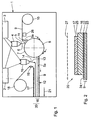
- Fig. 1
- schematisch eine Vorrichtung zur Herstellung eines Verbundes aus Kunststofflagen; und
- Fig. 2
- schematisch einen Schnitt durch einen mit der Vorrichtung nach
Fig. 1 hergestellten Verbund aus Kunststofflagen.
- Fig. 1
- schematically a device for producing a composite of plastic layers; and
- Fig. 2
- schematically a section through one with the device according to
Fig. 1 produced composite of plastic layers.
Eine Herstellungsvorrichtung 1, die in
In Umfangsrichtung im Uhrzeigersinn dem Aufgießpunkt der Kunststoffmasse 5a nachgeordnet wird auf die Trägerwalze 8 eine erste Kunststofflage 9 aufgelegt. Diese wird von einer Vorratsrolle 10 abgerollt und von einer vorzugsweise temperierbaren Umlenkrolle 11 kurz vor dem Aufbringen auf die Trägerwalze 8 umgelenkt. Die Kunststofflage 9 hat eine Stärke von 40µm, wobei die erste Schicht 22 ein Viertel dieser Schichtstärke und die zweite Schicht 23 drei Viertel dieser Schichtstärke aufweist. Die zweite Schicht 23 kann ihrerseits aus mehreren, zum Beispiel aus zwei Einzelschichten aufgebaut sein.Subordinate in the circumferential direction in the clockwise direction to the pouring point of the
Ab der Umfangsposition auf der Trägerwalze 8, bei der die Kunststofflage 9 beginnt, an der Trägerwalze 8 anzuliegen, wird ein hierdurch entstehender Verbund 12 aus der Kunststoffmasse 5a einerseits und der Kunststofflage 9 andererseits auf der rotierenden Trägerwalze 8 gefördert, wobei er an der Mantelwand 7 anliegt. Während dieses Förderweges, der einen Bruchteil einer vollen Umdrehung der Trägerwalze 8 beträgt, wird die Kunststoffmasse 5a verfestigt. Nachdem der Verbund 12 während dieses Fördervorgangs an einem Umfangsabschnitt der Trägerwalze 8 angelegen hat, wird der Verbund 12, der nun die verfestigte Kunststoffmasse 5a sowie die Kunststofflage 8 umfasst, von der Trägerwalze 8 abgezogen. Nach dem Abziehen wird auf den Verbund 12 zunächst eine weitere Kunststoffmasse 13 aufgegossen. Das Aufgießen der Kunststoffmasse 13 erfolgt auf die verfestigte Kunststoffmasse 5a des Verbunds 12. Ausgegossen wird die weitere Kunststoffmasse 13 als Film aus einer Schlitzdüse 14 einer weiteren Breitschlitzdüse 15. Letztere ist genauso aufgebaut wie die erste Breitschlitzdüse 4. Auch die Breitschlitzdüse 15 kann von den beiden Extrudern 2, 3 mit Kunststoffmasse, im vorliegenden Ausführungsbeispiel mit LDPE, versorgt werden.From the circumferential position on the
Da die nach dem Abziehen von der Trägerwalze 8 verfestigte Kunststoffmasse 5a aufgrund der dreidimensionalen Oberflächenstruktur der Mantelwand 7 der Trägerwalze 8 dreidimensional vorgeformt ist und da die weitere Kunststoffmasse 13 als ebener Film auf diese aufgegossen wird, entstehen zwischen den beiden Kunststoffmassenschichten Luftpolster, so dass aus diesen beiden Schichten eine insgesamt mit 16 bezeichnete Luftpolsterschicht entsteht. Die entstehenden Luftpolster sind in
Auf die Luftpolsterschicht 16 wird unmittelbar nach dem Aufgießen der weiteren Kunststoffmasse 13, d. h. dort, wo diese weitere Kunststoffmasse 13 noch nicht verfestigt vorliegt, eine weitere Kunststofflage 17, im vorliegenden Ausführungsbeispiel aus Schaumstoff, aufgebracht. Die Kunststofflage 17 aus PE (Polyethylen) hat eine Stärke von 1 mm. Diese weitere Kunststofflage 17 wird von einer Vorratsrolle 18 abgerollt und über eine vorzugsweise temperierbare Umlenkrolle 19 unmittelbar vor dem Aufbringen auf die Luftpolsterschicht 16 umgelenkt. Die Kunststofflage 9 und die Kunststofflage 17 werden über die temperierbaren Umlenkrollen 11, 19 auf eine entsprechende Temperatur im Bereich von 30°C gebracht. Der nach Aufbringen der weiteren Kunststofflage 17 entstandene Kunststofflagenverbund 20 wird nach dem Aufbringen der weiteren Kunststofflage 17 hin zu einer nicht dargestellten Wickeleinrichtung zum Aufwickeln auf eine Lagerrolle transportiert. Hierbei kühlt der Kunststofflagen-Verbund 20 ab, wobei die weitere Kunststoffmasse 13 sich vollständig verfestigt. Die beiden Kunststoffmassen 5a und 13 dienen also sowohl zum Aufbau der Luftpolsterschicht 16 als auch als Adhäsionsschichten zur Anbindung der Kunststofflage 9 einerseits und der Kunststofflage 17 andererseits. Die aus den Kunststoffmassen 5a und 13 nach dem Verfestigen von diesen entstehenden Kunststoffschichten haben eine Stärke von 70µm.On the
Wie dem in
Bei einer zweiten Variante einer Herstellvorrichtung 1 wird ein Kunststofflagen-Verbund 20 mit einer Kunststofflage 9 hergestellt, wobei die Kunststofflage 9 den gleichen Aufbau und die gleiche Schichtstärkenverteilung der Schichtstärken 22, 23 hat wie die Kunststofflage 9 nach
Mit der Herstellungsvorrichtung 1 kann auch ein alternativer Kunststofflagen-Verbund hergestellt werden, bei dem die weitere Kunststofflage 17 weggelassen ist, der also die Kunststofflage 9 und die Luftpolsterschicht 16 umfasst. Anstelle der Kunststofflage 17 aus Schaumstoff kann alternativ auch eine Kunststofflage 17 aus Vliesstoff auf die Luftpolsterschicht aufgebracht werden. Hierbei kann es sich insbesondere um eine Polypropylen-(PP) Vliesschicht handeln. Alternativ ist auch eine Vliesschicht aus einem anderen Polyolefin, insbesondere aus PE (Polyethylen) möglich. Die Vliesschicht kann mit Additiven getränkt sein. Schließlich ist eine Variante eines Kunststofflagen-Verbundes 20 möglich, bei dem die Kunststofflage 9 als Vliesstoffschicht ausgeführt ist.With the production device 1, an alternative plastic layer composite can be produced, in which the
Über die Kunststoffmassen 5a und 13 sind die hieran angrenzenden Schichten vollflächig miteinander verklebt. Alternativ ist es denkbar, die einzelnen Lagen 9, 16, 17 des Verbundes 20 nicht vollflächig, sondern nur abschnitts- oder segmentweise miteinander zu verkleben. Als weitere Variante ist es möglich, einen Kunststofflagen-Verbund mit einheitlicher Schichtbreite herzustellen, zum Beispiel einen Verbund aus zwei Kunststofflagen 9, 17 mit einer zwischenliegenden Luftpolsterschicht 16, wobei alle drei Lagen eine Breite von 1500 mm aufweisen.About the
Aus dem hergestellten Verbund 12 beziehungsweise 20 wird anschließend eine Schutzhülle hergestellt, die insbesondere zum Schutz von Möbelstücken dienen kann. Dies wird nachfolgend anhand des Verbundes 20 erläutert. Hierzu werden zwei Verbunde 20 spiegelsymmetrisch zu einer in
Die einzelnen Verbundlagen 9, 16, 17 können ihrerseits als Metall/Kunststoff-Verbunde ausgeführt sein. So können die einzelnen Lagen 9, 16, 17 z. B. als mit PE beschichtete Aluminiumfolien oder als metallisierte PE-Folien gestaltet sein.The individual
Die einzelnen Verbundlagen 9, 16, 17 bzw. die diese aufbauenden Einzelschichten 22, 23 können ein koirosionshemmendes Additiv, zum Beispiel auf Basis der VCI-Technologie aufweisen. Es reicht dabei, wenn eine der Verbundlagen 9, 16, 17 bzw. der Schichten 22, 23 ein korrosionshemmendes Additiv aufweist. Hierzu wird das korrosionshemmende Additiv in die Kunststoffmasse 5a bzw. 13 eingebracht, bevor die Kunststosmasse 5a bzw. 13 aufgegossen wird. Alternativ oder zusätzlich zum Einbringen eines korrosionshemmenden Additivs in eine schon bestehende Lage bzw. Schicht kann dem Verbund auch eine zusätzliche korrosionshemmende Lage bzw. Schicht hinzugefügt werden.The individual
Es resultiert ein Verbund, aus dem eine Schutzhülle hergestellt werden kann, die den mittels des Verbundes zu schützenden Gegenstand wirksam auch vor Korrosion schützt.The result is a composite from which a protective cover can be produced, which effectively protects the object to be protected by means of the composite against corrosion.
Claims (19)
- Composite (12; 20) of plastic layers (9, 16; 9, 16, 17) for packing goods, comprising- a first layer (9) comprising-- a first sublayer (22) of a plastic material that melts easily, and-- at least one second sublayer (23) of a plastic material that melts less easily when compared to the first sublayer (22), and- at least one second layer (16; 16, 17) which has a greater layer thickness than the first layer (9) and consists of a shock-absorbing plastic material,characterized in that- the plastic material of which at least one sublayer (22, 23) of the first layer (9) and/or at least a second layer (16; 16, 17) is composed includes an anti-corrosive; or- an additional sublayer and/or layer, including an anti-corrosive, is provided.
- Composite according to claim 1, characterized in that the first sublayer (22) is an LDPE sublayer.
- Composite according to claim 1 or 2, characterized in that the second sublayer (23) is an MDPE sublayer.
- Composite according to one of the claims 1 to 3, characterized by an air cushion layer (16) as second layer.
- Composite according to one of the claims 1 to 4, characterized by a fleece layer, in particular of polypropylene, as second layer.
- Composite according to one of the claims 1 to 5, characterized by a foam layer (17) as second layer.
- Composite according to one of the claims 1 to 6, characterized in that the layers (9, 16; 9, 16, 17) have a different width, in particular that the first layer (9) projects beyond the edge of the second layer (16).
- Composite according to one of the claims 1 to 7, characterized in that at least two second layers (16, 17) are provided, wherein one (16) of the second layers (16, 17) projects beyond the edge of the other (17) of the second layers (16, 17).
- Composite according to one of the claims 1 to 8, characterized by a composite design comprising a first plastic layer (9), a foam layer (17) as second layer and an air cushion layer (16) disposed between the first layer (9) and the foam layer (17).
- Composite according to claim 9, characterized in that the air cushion layer (16) is composed of two LDPE sublayers (5a, 13) of which at least one (5a) has air cushion bubbles.
- Composite according to claim 10, characterized in that the LDPE sublayers (5a, 13) of the air cushion layer (16) simultaneously serve as adhesion sublayers for the adhesion of additional layers (9; 9, 17) of the composite (12; 20).
- Protective cover, in particular for furniture, manufactured of at least one composite (12; 20) according to one of the claims 1 to 11.
- Protective cover according to claim 12, characterized by two composites (20) according to one of the claims 1 to 12 which are welded at the edges.
- Method for manufacturing a composite (12; 12, 20) of plastic layers (9, 16; 9, 16, 17) for packing goods according to one of the claims 1 to 13, comprising the following steps:- preparing a plastic material (5a, 13) that is capable of flowing;- pouring the plastic material (5a, 13) onto the outer wall (7) of a tempered support roller (8) in a way as to comply with a predefined width;- applying a plastic layer (9) to the support roller (8) in a way that the plastic material (5a), which has been applied and has not hardened yet, lies between the support roller (8) and the first sublayer (22) of the plastic layer (9);- conveying the composite (12) of hardened plastic material (5a) and plastic layer (9) over the support roller (8) during a fraction of a full revolution thereof;- removing the composite (12) of hardened plastic material (5a) and plastic layer (9) from the support roller (8);- adding an anti-corrosive to the plastic material (5a, 13) prior to the pouring thereof.
- Method according to claim 14, characterized in that during the conveyance, a formation of a three-dimensional surface structure of the plastic material (5a) occurs due to the adaptation thereof to the corresponding three-dimensional shape of the outer wall (7) of the support roller (8).
- Method according to claim 14 or 15, characterized in that after removal, another plastic layer (17) is applied to the composite (12) as follows:- preparing an additional plastic material (13) that is capable of flowing;- pouring the additional plastic material (13) onto the composite (12) of hardened first plastic material (5a) and plastic layer (9), which is available upon removal, in a way as to comply with a predefined width;- applying an additional plastic layer (17) to the composite (12) that is available upon removal in a way that the additional plastic material (13), which has been applied and has not hardened yet, lies between the composite (12) that is available upon removal and the second plastic layer (17);- hardening of the additional plastic material (13).
- Method according to one of the claims 14 to 16, characterized in that the plastic material (5a, 13) that is capable of flowing, in particular a polyolefin, is prepared by extrusion.
- Method according to one of the claims 14 to 17, characterized in that the plastic material (5a, 13) is applied by means of a slot nozzle (4, 15) whose width is preferably adjustable.
- Method for manufacturing a protective cover, in particular for furniture, of at least two composites (12, 20), manufactured according to one of the claims 14 to 18, characterized by a welding of the composites (12; 20) at the edges thereof so as to form a cover which is open on one side.
Priority Applications (1)
| Application Number | Priority Date | Filing Date | Title |
|---|---|---|---|
| PL05008723T PL1588844T3 (en) | 2004-04-22 | 2005-04-21 | Composite material with impact absorbing layer |
Applications Claiming Priority (2)
| Application Number | Priority Date | Filing Date | Title |
|---|---|---|---|
| DE102004019537 | 2004-04-22 | ||
| DE102004019537A DE102004019537A1 (en) | 2004-04-22 | 2004-04-22 | Composite of plastic layers for packaging objects, protective cover, in particular for pieces of furniture, made of at least one such composite, method for producing such a composite and for producing such a protective cover |
Publications (2)
| Publication Number | Publication Date |
|---|---|
| EP1588844A1 EP1588844A1 (en) | 2005-10-26 |
| EP1588844B1 true EP1588844B1 (en) | 2008-04-09 |
Family
ID=34935509
Family Applications (1)
| Application Number | Title | Priority Date | Filing Date |
|---|---|---|---|
| EP05008723A Active EP1588844B1 (en) | 2004-04-22 | 2005-04-21 | Composite material with impact absorbing layer |
Country Status (4)
| Country | Link |
|---|---|
| EP (1) | EP1588844B1 (en) |
| AT (1) | ATE391599T1 (en) |
| DE (2) | DE102004019537A1 (en) |
| PL (1) | PL1588844T3 (en) |
Cited By (1)
| Publication number | Priority date | Publication date | Assignee | Title |
|---|---|---|---|---|
| DE202012006764U1 (en) | 2012-07-12 | 2013-10-15 | Verpa Folie Weidhausen Gmbh | Foil packaging material and packaging hood of such a foil packaging material |
Family Cites Families (8)
| Publication number | Priority date | Publication date | Assignee | Title |
|---|---|---|---|---|
| DE2554151A1 (en) * | 1975-12-02 | 1977-06-08 | Bp Benzin Und Petroleum Ag | Packaging material for sharp edged vacuum packed objects - embodies cushioning film laminated with impermeable weldable material |
| DK160036C (en) * | 1988-10-27 | 1991-06-10 | Nielsen Emballage | LAMINATE, NECESSARY FOR PACKAGING FOOD OR FOOD, AND PROCEDURE FOR MANUFACTURING THE LAMINATE |
| ZA943397B (en) * | 1993-05-17 | 1995-02-09 | Colpak Proprietary Limited | Casings for containing pastes |
| US5863642A (en) * | 1996-07-26 | 1999-01-26 | Fabrene, Inc. | Water resistant and vapor phase corrosion inhibitor composite material |
| DE19634872A1 (en) * | 1996-08-29 | 1998-03-05 | Haweka Kunststoff Engineering | Multilayer plastic sheeting used for e.g. delicate optical, electronic or data storage media |
| DE19840046A1 (en) * | 1998-09-02 | 2000-03-09 | Convenience Food Sys Bv | Packaging material with a layer of foamed polyolefin |
| DE10100698A1 (en) * | 2000-12-22 | 2002-06-27 | Manfred Schneider | Multi-layer embossed plastic film or strip production for use in electronics, furniture and cheque cards uses several chill roll extruders to laminate decorative layers with extruded plastic layers |
| DE10101966B4 (en) * | 2001-01-17 | 2004-07-08 | Göbel, Klaus-Ulrich | Thermal insulation and / or soundproofing material |
-
2004
- 2004-04-22 DE DE102004019537A patent/DE102004019537A1/en not_active Withdrawn
-
2005
- 2005-04-21 DE DE502005003608T patent/DE502005003608D1/en active Active
- 2005-04-21 EP EP05008723A patent/EP1588844B1/en active Active
- 2005-04-21 PL PL05008723T patent/PL1588844T3/en unknown
- 2005-04-21 AT AT05008723T patent/ATE391599T1/en active
Cited By (2)
| Publication number | Priority date | Publication date | Assignee | Title |
|---|---|---|---|---|
| DE202012006764U1 (en) | 2012-07-12 | 2013-10-15 | Verpa Folie Weidhausen Gmbh | Foil packaging material and packaging hood of such a foil packaging material |
| DE102012216768A1 (en) | 2012-07-12 | 2014-01-16 | Verpa Folie Weidhausen Gmbh | Film packing material of packaging hood, has base layer whose sections are covered by additive layer, and base layer and waving layer that are connected through ultrasonic sealing connection process |
Also Published As
| Publication number | Publication date |
|---|---|
| ATE391599T1 (en) | 2008-04-15 |
| EP1588844A1 (en) | 2005-10-26 |
| DE502005003608D1 (en) | 2008-05-21 |
| PL1588844T3 (en) | 2008-08-29 |
| DE102004019537A1 (en) | 2005-11-10 |
Similar Documents
| Publication | Publication Date | Title |
|---|---|---|
| DE2620295A1 (en) | PIPE WALL MATERIAL AND METHOD OF MANUFACTURING THE SAME | |
| EP3715114A1 (en) | Packaging bag made of plastic tissue composite | |
| DE1446726A1 (en) | Layer material | |
| DE2647166A1 (en) | LAMINATED PACKAGING MATERIAL AND METHOD OF MANUFACTURING THEREOF | |
| DE3514667C2 (en) | Process for producing a folding box from a cushion layer material | |
| EP0809571B1 (en) | Process for producing packaging materials with a layer of foamed polyolefine | |
| EP0669195B1 (en) | Shaped article of composite material and method of making it | |
| DE3239167A1 (en) | COEXTRUDED THERMOPLASTIC COMPOSITE FILM AND METHOD FOR THEIR PRODUCTION | |
| DE2618504A1 (en) | PROCESS FOR PRODUCING NON-SLIP PLASTIC FILMS, DEVICE FOR CARRYING OUT THE PROCESS, AND PLASTIC FILM PRODUCED BY THE PROCESS | |
| DE202010018143U1 (en) | Polypropylene packaging with opening aid | |
| DE2127167A1 (en) | Coated fabric made from thermoplastic plastics | |
| DE102006056612A1 (en) | Production of sandwich-type composite for lightweight constructions, e.g. inside cars, involves cutting a core layer from a rigid foam block with an unserrated blade and glueing on tensionally-rigid film as outer layers | |
| DE1486175A1 (en) | Collapsible container | |
| EP3453806B2 (en) | Seal element | |
| EP1588844B1 (en) | Composite material with impact absorbing layer | |
| EP3500420B1 (en) | Method for producing a fiber-reinforced plastic component | |
| EP2490884B1 (en) | Method for producing packaging, in particular tubes, and packaging | |
| DE202005002615U1 (en) | Foamed plastic packaging film produced by adding a blowing agent to a plastic and foaming the film with the blowing agent | |
| DE3314108A1 (en) | METHOD AND DEVICE FOR PRODUCING HOLLOW BODIES WITH AT LEAST AREAS OF TWO OR MULTILAYERED WALL | |
| DE2337677A1 (en) | Thermoplastic articles with unpolluted surface - made by applying protective covering at first extrusion stage | |
| DE2338431A1 (en) | DRAWING PROCEDURE | |
| DE2619297C3 (en) | Process for the production of free-flowing bulk material from atactic polyolefins | |
| EP0248398A2 (en) | Packaging bag | |
| WO1996011118A1 (en) | Plastics-paper composite in foil-form and its use for producing weatherproof laminated sheets with surface protection | |
| DE19604692A1 (en) | Multilayer constructional element |
Legal Events
| Date | Code | Title | Description |
|---|---|---|---|
| PUAI | Public reference made under article 153(3) epc to a published international application that has entered the european phase |
Free format text: ORIGINAL CODE: 0009012 |
|
| AK | Designated contracting states |
Kind code of ref document: A1 Designated state(s): AT BE BG CH CY CZ DE DK EE ES FI FR GB GR HU IE IS IT LI LT LU MC NL PL PT RO SE SI SK TR |
|
| AX | Request for extension of the european patent |
Extension state: AL BA HR LV MK YU |
|
| 17P | Request for examination filed |
Effective date: 20060111 |
|
| AKX | Designation fees paid |
Designated state(s): AT BE BG CH CY CZ DE DK EE ES FI FR GB GR HU IE IS IT LI LT LU MC NL PL PT RO SE SI SK TR |
|
| GRAP | Despatch of communication of intention to grant a patent |
Free format text: ORIGINAL CODE: EPIDOSNIGR1 |
|
| GRAS | Grant fee paid |
Free format text: ORIGINAL CODE: EPIDOSNIGR3 |
|
| GRAA | (expected) grant |
Free format text: ORIGINAL CODE: 0009210 |
|
| AK | Designated contracting states |
Kind code of ref document: B1 Designated state(s): AT BE BG CH CY CZ DE DK EE ES FI FR GB GR HU IE IS IT LI LT LU MC NL PL PT RO SE SI SK TR |
|
| REG | Reference to a national code |
Ref country code: GB Ref legal event code: FG4D Free format text: NOT ENGLISH |
|
| REG | Reference to a national code |
Ref country code: CH Ref legal event code: EP |
|
| REG | Reference to a national code |
Ref country code: IE Ref legal event code: FG4D Free format text: LANGUAGE OF EP DOCUMENT: GERMAN |
|
| REF | Corresponds to: |
Ref document number: 502005003608 Country of ref document: DE Date of ref document: 20080521 Kind code of ref document: P |
|
| REG | Reference to a national code |
Ref country code: PL Ref legal event code: T3 |
|
| PG25 | Lapsed in a contracting state [announced via postgrant information from national office to epo] |
Ref country code: SI Free format text: LAPSE BECAUSE OF FAILURE TO SUBMIT A TRANSLATION OF THE DESCRIPTION OR TO PAY THE FEE WITHIN THE PRESCRIBED TIME-LIMIT Effective date: 20080409 |
|
| NLV1 | Nl: lapsed or annulled due to failure to fulfill the requirements of art. 29p and 29m of the patents act | ||
| BERE | Be: lapsed |
Owner name: ALL-PLASTIC KUNSTOFFWERK GUNZENHAUSEN G.M.B.H. Effective date: 20080430 |
|
| PG25 | Lapsed in a contracting state [announced via postgrant information from national office to epo] |
Ref country code: ES Free format text: LAPSE BECAUSE OF FAILURE TO SUBMIT A TRANSLATION OF THE DESCRIPTION OR TO PAY THE FEE WITHIN THE PRESCRIBED TIME-LIMIT Effective date: 20080720 Ref country code: PT Free format text: LAPSE BECAUSE OF FAILURE TO SUBMIT A TRANSLATION OF THE DESCRIPTION OR TO PAY THE FEE WITHIN THE PRESCRIBED TIME-LIMIT Effective date: 20080910 Ref country code: FI Free format text: LAPSE BECAUSE OF FAILURE TO SUBMIT A TRANSLATION OF THE DESCRIPTION OR TO PAY THE FEE WITHIN THE PRESCRIBED TIME-LIMIT Effective date: 20080409 Ref country code: NL Free format text: LAPSE BECAUSE OF FAILURE TO SUBMIT A TRANSLATION OF THE DESCRIPTION OR TO PAY THE FEE WITHIN THE PRESCRIBED TIME-LIMIT Effective date: 20080409 Ref country code: BG Free format text: LAPSE BECAUSE OF FAILURE TO SUBMIT A TRANSLATION OF THE DESCRIPTION OR TO PAY THE FEE WITHIN THE PRESCRIBED TIME-LIMIT Effective date: 20080709 |
|
| PG25 | Lapsed in a contracting state [announced via postgrant information from national office to epo] |
Ref country code: MC Free format text: LAPSE BECAUSE OF NON-PAYMENT OF DUE FEES Effective date: 20080430 |
|
| REG | Reference to a national code |
Ref country code: IE Ref legal event code: FD4D |
|
| PG25 | Lapsed in a contracting state [announced via postgrant information from national office to epo] |
Ref country code: IS Free format text: LAPSE BECAUSE OF FAILURE TO SUBMIT A TRANSLATION OF THE DESCRIPTION OR TO PAY THE FEE WITHIN THE PRESCRIBED TIME-LIMIT Effective date: 20080809 |
|
| EN | Fr: translation not filed | ||
| PG25 | Lapsed in a contracting state [announced via postgrant information from national office to epo] |
Ref country code: IE Free format text: LAPSE BECAUSE OF FAILURE TO SUBMIT A TRANSLATION OF THE DESCRIPTION OR TO PAY THE FEE WITHIN THE PRESCRIBED TIME-LIMIT Effective date: 20080409 Ref country code: EE Free format text: LAPSE BECAUSE OF FAILURE TO SUBMIT A TRANSLATION OF THE DESCRIPTION OR TO PAY THE FEE WITHIN THE PRESCRIBED TIME-LIMIT Effective date: 20080409 Ref country code: LT Free format text: LAPSE BECAUSE OF FAILURE TO SUBMIT A TRANSLATION OF THE DESCRIPTION OR TO PAY THE FEE WITHIN THE PRESCRIBED TIME-LIMIT Effective date: 20080409 Ref country code: SE Free format text: LAPSE BECAUSE OF FAILURE TO SUBMIT A TRANSLATION OF THE DESCRIPTION OR TO PAY THE FEE WITHIN THE PRESCRIBED TIME-LIMIT Effective date: 20080709 Ref country code: DK Free format text: LAPSE BECAUSE OF FAILURE TO SUBMIT A TRANSLATION OF THE DESCRIPTION OR TO PAY THE FEE WITHIN THE PRESCRIBED TIME-LIMIT Effective date: 20080409 |
|
| PLBE | No opposition filed within time limit |
Free format text: ORIGINAL CODE: 0009261 |
|
| STAA | Information on the status of an ep patent application or granted ep patent |
Free format text: STATUS: NO OPPOSITION FILED WITHIN TIME LIMIT |
|
| PG25 | Lapsed in a contracting state [announced via postgrant information from national office to epo] |
Ref country code: RO Free format text: LAPSE BECAUSE OF FAILURE TO SUBMIT A TRANSLATION OF THE DESCRIPTION OR TO PAY THE FEE WITHIN THE PRESCRIBED TIME-LIMIT Effective date: 20080409 Ref country code: SK Free format text: LAPSE BECAUSE OF FAILURE TO SUBMIT A TRANSLATION OF THE DESCRIPTION OR TO PAY THE FEE WITHIN THE PRESCRIBED TIME-LIMIT Effective date: 20080409 |
|
| 26N | No opposition filed |
Effective date: 20090112 |
|
| REG | Reference to a national code |
Ref country code: HU Ref legal event code: AG4A Ref document number: E004365 Country of ref document: HU |
|
| PG25 | Lapsed in a contracting state [announced via postgrant information from national office to epo] |
Ref country code: BE Free format text: LAPSE BECAUSE OF NON-PAYMENT OF DUE FEES Effective date: 20080430 |
|
| PG25 | Lapsed in a contracting state [announced via postgrant information from national office to epo] |
Ref country code: FR Free format text: LAPSE BECAUSE OF FAILURE TO SUBMIT A TRANSLATION OF THE DESCRIPTION OR TO PAY THE FEE WITHIN THE PRESCRIBED TIME-LIMIT Effective date: 20090130 |
|
| PG25 | Lapsed in a contracting state [announced via postgrant information from national office to epo] |
Ref country code: IT Free format text: LAPSE BECAUSE OF FAILURE TO SUBMIT A TRANSLATION OF THE DESCRIPTION OR TO PAY THE FEE WITHIN THE PRESCRIBED TIME-LIMIT Effective date: 20080409 |
|
| PG25 | Lapsed in a contracting state [announced via postgrant information from national office to epo] |
Ref country code: CY Free format text: LAPSE BECAUSE OF FAILURE TO SUBMIT A TRANSLATION OF THE DESCRIPTION OR TO PAY THE FEE WITHIN THE PRESCRIBED TIME-LIMIT Effective date: 20080409 |
|
| GBPC | Gb: european patent ceased through non-payment of renewal fee |
Effective date: 20090421 |
|
| PG25 | Lapsed in a contracting state [announced via postgrant information from national office to epo] |
Ref country code: GB Free format text: LAPSE BECAUSE OF NON-PAYMENT OF DUE FEES Effective date: 20090421 |
|
| PG25 | Lapsed in a contracting state [announced via postgrant information from national office to epo] |
Ref country code: LU Free format text: LAPSE BECAUSE OF NON-PAYMENT OF DUE FEES Effective date: 20080421 |
|
| PG25 | Lapsed in a contracting state [announced via postgrant information from national office to epo] |
Ref country code: TR Free format text: LAPSE BECAUSE OF FAILURE TO SUBMIT A TRANSLATION OF THE DESCRIPTION OR TO PAY THE FEE WITHIN THE PRESCRIBED TIME-LIMIT Effective date: 20080409 |
|
| PG25 | Lapsed in a contracting state [announced via postgrant information from national office to epo] |
Ref country code: GR Free format text: LAPSE BECAUSE OF FAILURE TO SUBMIT A TRANSLATION OF THE DESCRIPTION OR TO PAY THE FEE WITHIN THE PRESCRIBED TIME-LIMIT Effective date: 20080710 |
|
| PGFP | Annual fee paid to national office [announced via postgrant information from national office to epo] |
Ref country code: CH Payment date: 20140319 Year of fee payment: 10 |
|
| PGFP | Annual fee paid to national office [announced via postgrant information from national office to epo] |
Ref country code: CZ Payment date: 20140411 Year of fee payment: 10 Ref country code: AT Payment date: 20140320 Year of fee payment: 10 |
|
| PGFP | Annual fee paid to national office [announced via postgrant information from national office to epo] |
Ref country code: HU Payment date: 20140414 Year of fee payment: 10 |
|
| REG | Reference to a national code |
Ref country code: CH Ref legal event code: PL |
|
| REG | Reference to a national code |
Ref country code: AT Ref legal event code: MM01 Ref document number: 391599 Country of ref document: AT Kind code of ref document: T Effective date: 20150421 |
|
| PG25 | Lapsed in a contracting state [announced via postgrant information from national office to epo] |
Ref country code: CH Free format text: LAPSE BECAUSE OF NON-PAYMENT OF DUE FEES Effective date: 20150430 Ref country code: LI Free format text: LAPSE BECAUSE OF NON-PAYMENT OF DUE FEES Effective date: 20150430 |
|
| PG25 | Lapsed in a contracting state [announced via postgrant information from national office to epo] |
Ref country code: CZ Free format text: LAPSE BECAUSE OF NON-PAYMENT OF DUE FEES Effective date: 20150421 Ref country code: AT Free format text: LAPSE BECAUSE OF NON-PAYMENT OF DUE FEES Effective date: 20150421 Ref country code: HU Free format text: LAPSE BECAUSE OF NON-PAYMENT OF DUE FEES Effective date: 20150422 |
|
| PGFP | Annual fee paid to national office [announced via postgrant information from national office to epo] |
Ref country code: DE Payment date: 20220525 Year of fee payment: 18 |
|
| PGFP | Annual fee paid to national office [announced via postgrant information from national office to epo] |
Ref country code: PL Payment date: 20220408 Year of fee payment: 18 |
|
| REG | Reference to a national code |
Ref country code: DE Ref legal event code: R119 Ref document number: 502005003608 Country of ref document: DE |
|
| PG25 | Lapsed in a contracting state [announced via postgrant information from national office to epo] |
Ref country code: DE Free format text: LAPSE BECAUSE OF NON-PAYMENT OF DUE FEES Effective date: 20231103 |