EP1588770B1 - Austragkopf für eine Dosiereinrichtung - Google Patents
Austragkopf für eine Dosiereinrichtung Download PDFInfo
- Publication number
- EP1588770B1 EP1588770B1 EP05007347A EP05007347A EP1588770B1 EP 1588770 B1 EP1588770 B1 EP 1588770B1 EP 05007347 A EP05007347 A EP 05007347A EP 05007347 A EP05007347 A EP 05007347A EP 1588770 B1 EP1588770 B1 EP 1588770B1
- Authority
- EP
- European Patent Office
- Prior art keywords
- nozzle
- discharge head
- component
- receptacle
- disc
- Prior art date
- Legal status (The legal status is an assumption and is not a legal conclusion. Google has not performed a legal analysis and makes no representation as to the accuracy of the status listed.)
- Expired - Lifetime
Links
- 239000007788 liquid Substances 0.000 abstract description 6
- 239000004033 plastic Substances 0.000 abstract description 6
- 239000007921 spray Substances 0.000 abstract description 4
- 239000002537 cosmetic Substances 0.000 abstract description 3
- 238000010276 construction Methods 0.000 abstract 1
- 230000002093 peripheral effect Effects 0.000 description 5
- 238000005086 pumping Methods 0.000 description 4
- 239000000243 solution Substances 0.000 description 4
- 238000003780 insertion Methods 0.000 description 2
- 230000037431 insertion Effects 0.000 description 2
- 230000014759 maintenance of location Effects 0.000 description 2
- 238000000034 method Methods 0.000 description 2
- 238000005507 spraying Methods 0.000 description 2
- 238000002347 injection Methods 0.000 description 1
- 239000007924 injection Substances 0.000 description 1
- 238000001746 injection moulding Methods 0.000 description 1
- 239000004413 injection moulding compound Substances 0.000 description 1
- 238000004519 manufacturing process Methods 0.000 description 1
- 238000007789 sealing Methods 0.000 description 1
- 239000012815 thermoplastic material Substances 0.000 description 1
Images
Classifications
-
- B—PERFORMING OPERATIONS; TRANSPORTING
- B05—SPRAYING OR ATOMISING IN GENERAL; APPLYING FLUENT MATERIALS TO SURFACES, IN GENERAL
- B05B—SPRAYING APPARATUS; ATOMISING APPARATUS; NOZZLES
- B05B1/00—Nozzles, spray heads or other outlets, with or without auxiliary devices such as valves, heating means
- B05B1/34—Nozzles, spray heads or other outlets, with or without auxiliary devices such as valves, heating means designed to influence the nature of flow of the liquid or other fluent material, e.g. to produce swirl
- B05B1/3405—Nozzles, spray heads or other outlets, with or without auxiliary devices such as valves, heating means designed to influence the nature of flow of the liquid or other fluent material, e.g. to produce swirl to produce swirl
- B05B1/341—Nozzles, spray heads or other outlets, with or without auxiliary devices such as valves, heating means designed to influence the nature of flow of the liquid or other fluent material, e.g. to produce swirl to produce swirl before discharging the liquid or other fluent material, e.g. in a swirl chamber upstream the spray outlet
- B05B1/3421—Nozzles, spray heads or other outlets, with or without auxiliary devices such as valves, heating means designed to influence the nature of flow of the liquid or other fluent material, e.g. to produce swirl to produce swirl before discharging the liquid or other fluent material, e.g. in a swirl chamber upstream the spray outlet with channels emerging substantially tangentially in the swirl chamber
- B05B1/3431—Nozzles, spray heads or other outlets, with or without auxiliary devices such as valves, heating means designed to influence the nature of flow of the liquid or other fluent material, e.g. to produce swirl to produce swirl before discharging the liquid or other fluent material, e.g. in a swirl chamber upstream the spray outlet with channels emerging substantially tangentially in the swirl chamber the channels being formed at the interface of cooperating elements, e.g. by means of grooves
- B05B1/3436—Nozzles, spray heads or other outlets, with or without auxiliary devices such as valves, heating means designed to influence the nature of flow of the liquid or other fluent material, e.g. to produce swirl to produce swirl before discharging the liquid or other fluent material, e.g. in a swirl chamber upstream the spray outlet with channels emerging substantially tangentially in the swirl chamber the channels being formed at the interface of cooperating elements, e.g. by means of grooves the interface being a plane perpendicular to the outlet axis
-
- B—PERFORMING OPERATIONS; TRANSPORTING
- B05—SPRAYING OR ATOMISING IN GENERAL; APPLYING FLUENT MATERIALS TO SURFACES, IN GENERAL
- B05B—SPRAYING APPARATUS; ATOMISING APPARATUS; NOZZLES
- B05B11/00—Single-unit hand-held apparatus in which flow of contents is produced by the muscular force of the operator at the moment of use
- B05B11/01—Single-unit hand-held apparatus in which flow of contents is produced by the muscular force of the operator at the moment of use characterised by the means producing the flow
- B05B11/10—Pump arrangements for transferring the contents from the container to a pump chamber by a sucking effect and forcing the contents out through the dispensing nozzle
Definitions
- the invention relates to a discharge head for a metering device according to the preamble of claim 1.
- a discharge head for a metering device for applying a medium is known from DE 198 13 078 A1 known.
- the discharge head is made of plastic and is provided with an integrated flow channel arrangement.
- the flow channel arrangement can be connected to a flow path of the pump unit.
- the flow channel arrangement has a flow channel section extending radially to a central longitudinal axis of the discharge head, which opens into a swirling unit which serves as a flow-guiding unit for the outflowing medium.
- the swirling unit is formed integrally in the cap-shaped discharge head.
- In front of an outlet opening of the discharge head, which follows the swirling unit, is provided with an outlet nozzle Slider member arranged, which represents a separate nozzle member.
- the slide member is made of plastic and preferably made in one piece and together with the discharge head.
- a rest position which is defined after the manufacture of the components, the slider component via the finest injection-molding compounds on the input side of a transverse to the flow channel arrangement and serving as a recording slide groove is held.
- the fine connections are separated, so that the slide component can be displaced downwards in the slide groove, whereby the outlet nozzle integrated in the slide component is positioned in front of the swirling unit.
- the discharge head is now in a functional position in which a discharge operation of the particular liquid medium, preferably a spraying, can take place when the discharge head is placed on the pump unit.
- the object of the invention is to provide a discharge head of the type mentioned, which can be designed extremely gariliat and can be produced in a simple manner.
- the solution according to the invention makes it possible in an extremely simple manner to mount the nozzle component in the receptacle of the discharge head and thus to achieve a functioning discharge head.
- the disk-shaped and symmetrical to the nozzle exit axis taking place Design of the nozzle component allows an undirected mounting of the nozzle member. This means that the nozzle component can be used in any position in the recording and without subsequent alignment has reached the desired end position with the insertion.
- the receptacle is adapted in its dimensions to the nozzle component in such a way that the nozzle component can be inserted flush into the receptacle.
- the solution according to the invention is particularly suitable for metering devices which discharge liquid media.
- the nozzle component is preferably configured such that the nozzle component defines a spray nozzle together with the flow-guiding unit and the nozzle outlet.
- the solution according to the invention is particularly suitable for use in the cosmetics sector or in the pharmaceutical sector.
- particularly particularly small-sized discharge heads can be achieved.
- the invention can be used particularly advantageously for metering pumps which have a pump diameter of less than 9 mm. These are miniaturized dosing pumps.
- the discharge head is preferably also provided with a diameter which is smaller than 9 mm.
- the receptacle is designed coaxially to the nozzle exit axis open to the outside so that the nozzle member along the nozzle exit axis in the receptacle can be mounted.
- the insertion of the nozzle component along the nozzle exit axis in the receptacle advantageously allows in a single step already an exact and final positioning of the nozzle member in the receptacle and thus in the discharge head.
- the disc-shaped nozzle member is designed rotationally symmetrical to the nozzle exit axis. This results in particular a flat cylindrical disk, which preferably has a corresponding nozzle opening coaxial with the nozzle exit axis in its center.
- the nozzle member is designed mirror-symmetrically to a related to the nozzle exit axis radial center plane. This makes it possible to use the nozzle member both in a first orientation and in a second, mirror-inverted orientation in the recording and still achieve the same nozzle function in both cases.
- securing means for fixing the nozzle component in the receptacle are associated with the receptacle.
- the securing means serve to fix the nozzle member positively or non-positively in the receptacle.
- a separate securing component is provided, which is connectable to the discharge head and in its securing position, the nozzle member positively or non-positively retains in the recording.
- the securing component is preferably designed cap or sleeve-like and can be plugged or pushed onto the discharge head.
- the cap or sleeve-shaped securing member may have a passage opening whose diameter is slightly larger than a diameter of the nozzle outlet.
- the securing component is guided during its assembly on the discharge head such that the passage opening is necessarily positioned coaxially with the nozzle exit.
- the passage opening can be rotated either coaxially in front of the nozzle outlet, or the Passage opening is rotated when not in use so that the passage opening is offset to the nozzle outlet.
- a corresponding skirt portion of the securing component closes the nozzle outlet.
- the securing component is designed in the described embodiment as an outer sleeve which engages over the discharge head at least in the region of the receptacle outside.
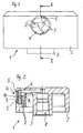
- a discharge head 1 according to the Fig. 1 and 2 is in Fig. 1 shown in greatly enlarged representation. Also the sectional view after Fig. 2 represents a multiple enlargement of the actual dimensions of the discharge head 1.
- the discharge head 1 after the Fig. 1 and 2 is used for dosing devices that are provided with mechanical pumping units, in particular with piston pumps. Such metering devices are used for dispensing liquid media from the cosmetics or pharmaceutical sector.
- the discharge head 1 according to the Fig. 1 and 2 an actual diameter of less than 9 mm. With these small dimensions is the discharge head 1 advantageously part of a miniaturized metering device, since the other parts of the metering device preferably have no larger diameter than the discharge head. 1
- the discharge head 1 is made of a thermoplastic material by injection molding in one piece.
- the discharge head 1 is a cap-shaped component and has an outer shell 2, which is designed substantially cylindrical. Coaxially within the outer shell 2, a sleeve-shaped collar portion 3 is provided which, like the outer shell 2, is open at the bottom.
- the collar portion 3 serves to attach the discharge head 1 to an outlet region, not shown, of a pumping unit of the metering device and thus to connect the discharge head 1 to a flow path of the pumping unit.
- the metering device preferably has a medium reservoir in addition to the pumping unit.
- the collar section 3 surrounds a first flow channel section of a flow channel arrangement within the discharge head 1.
- the coaxially extending first flow channel section 8 merges into a second, radially aligned flow channel section 6, which leads to an outlet opening 4 of the discharge head 1.
- an unspecified receiving area for a nozzle disk 9 is provided in front of the outlet opening 4.
- a flow-guiding unit in the form of a swirl arrangement 7 is provided, which is based on the Fig. 1 is clearly recognizable.
- Both the receiving area and the swirling arrangement 7 have an axis of symmetry which corresponds to an exit axis A of the exit opening 4.
- the exit axis A is at right angles to an unspecified center longitudinal axis of the discharge head 1 and preferably aligned radially thereto.
- the second flow channel section 6 opens in an upper region of the swirling arrangement 7 and the receiving area, as shown in FIG Fig. 2 is recognizable.
- the receiving area serves to accommodate a nozzle disk 9, which is designed rotationally symmetrical.
- the nozzle disk 9 has a circular shape in plan view and is provided centrally with a passage in the form of a nozzle opening 10.
- the receiving area is matched in its dimensions to the nozzle plate 9 that the nozzle plate 9 in its assembled state according to Fig. 2 sits flush in the receiving area.
- a nozzle axis of the nozzle opening 10 is identical to the exit axis A.
- the nozzle plate is also mirror-symmetrically aligned with respect to a radial center plane related to the nozzle exit axis A.
- the nozzle plate 9 is designed as a one-piece plastic body, which is provided with a rounded in cross section, peripheral peripheral or edge region.
- the outlet opening 4 has a circular edge contour.
- the edge contour has a diameter which is smaller than a diameter of the receiving area, which has a circular or cylindrical edge contour.
- the edge contour of the receiving area is matched to the diameter of the nozzle disk 9 so that the receiving area for the nozzle disk 9 ensures a substantially backlash-free seat.
- the depth of the receiving area is also matched to the thickness of the nozzle disk 9, so that the nozzle disk 9 is held axially flush in the receiving area.
- the peripheral edge contour of the outlet opening 4 forms a circumferential latching edge 5.
- the nozzle disk For mounting the nozzle disk 9, the nozzle disk is formed 9 positioned in front of the outlet opening 4 and then pressed into the receiving area while applying an axial compressive force. Since the nozzle disk 9 and also the latching edge of the edge contour of the outlet opening 4 are made of plastic, a certain elastic compliance of the edge contour of the outlet opening 4 on the one hand and the edge of the nozzle disk 9 on the other hand ensured, so that an injection of the nozzle plate 9 is possible.
- the latching rim 5 thus engages behind the positive, backlash-free retention of the nozzle disk 9.
- the form-fitting retaining forces which the latching rim 5 exerts on the nozzle disk 9 cause a peripheral sealing function, so that the nozzle disk 9 is sealed in FIG the recording area is held.
- Liquid can therefore only pass out through the central nozzle opening 10 to the outside.
- the positive retaining forces are dimensioned so large that no pushing out of the nozzle disk 9 is made possible with the liquid medium conveyed under strong overpressure within the two flow channel sections 6, 8 to the outlet opening 4.
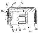
- a discharge head 1a is provided, which is substantially the discharge head according to the Fig. 1 and 2 equivalent. Except for the differences described below, the entire disclosure of the embodiment of the discharge head 1 according to the Fig. 1 and 2 also for the discharge head 1a. Functionally identical or identical components or portions of the discharge head 1a are denoted by identical reference numerals as in the discharge head 1 according to the Fig. 1 and 2 but with the addition of the letter a.
- the essential difference in the discharge head 1a is that the receiving region adjoining the swirl arrangement 7a and the second flow channel section 6a for receiving the nozzle disk 9 is arranged directly outside the outer casing 2a of the discharge head 1a.
- the outlet opening 4a is in a separate securing component provided in the form of a sleeve-like securing hood 5a, which is frictionally pushed from above via the discharge head 1a and outer casing 2a.
- the outlet opening 4a has a substantially smaller diameter than the receiving area for the nozzle disk 9.
- the outlet opening 4a is positioned coaxially in front of the nozzle axis of the nozzle disk 9.
- a circumferential edge contour of the outlet opening 4a thus serves necessarily as a peripheral edge projection, which causes the positive retention of the nozzle disk 9 in the receiving area.
- the inner diameter of the securing hood 5a is slightly smaller than the outer diameter of the outer jacket 2a, so that a secure adhesion of the securing hood 5a is ensured in its mounted on the outer jacket 2a state.
- the outlet opening can be brought into a position aligned with the nozzle opening of the nozzle disk or into a position rotated relative to the nozzle disk.
- a jacket portion of the securing hood completely covers the nozzle disk, so that no discharge process is possible.
- a corresponding spraying process can take place.
- the outer jacket of the discharge head and the securing hood each have a polygonal outer contour. These polygonal outer contours ensure that the safety hood can be snapped onto the outer sheath and then not twisted can. The plugging is done in such a way that inevitably the outlet opening is positioned in alignment in front of the nozzle disk.
- the securing component is designed so that it covers only a portion of the outer shell when placed on the outer shell, by the nozzle disk and the outlet opening of the discharge head is positioned.
- a security component can then represent in particular a half shell shape or a similar rotationally asymmetric component.
Landscapes
- Closures For Containers (AREA)
- Containers And Packaging Bodies Having A Special Means To Remove Contents (AREA)
- Coating Apparatus (AREA)
- Nozzles (AREA)
Description
- Die Erfindung betrifft einen Austragkopf für eine Dosiereinrichtung nach dem Oberbegriff von Anspruch 1.
- Ein Austragkopf für eine Dosiereinrichtung zur Ausbringung eines Mediums ist aus der
DE 198 13 078 A1 bekannt. Der Austragkopf besteht aus Kunststoff und ist mit einer integrierten Strömungskanalanordnung versehen. Durch Aufstecken des Austragkopfes auf eine Pumpeinheit kann die Strömungskanalanordnung mit einem Strömungsweg der Pumpeinheit verbunden werden. Die Strömungskanalanordnung weist einen radial zu einer Mittellängsachse des Austragkopfes verlaufenden Strömungskanalabschnitt auf, der in eine Drallgebungseinheit mündet, die als Strömungsleiteinheit für das ausströmende Medium dient. Die Drallgebungseinheit ist einstückig in dem kappenförmig gestalteten Austragkopf ausgeformt. Vor einer Austrittsöffnung des Austragkopfes, die auf die Drallgebungseinheit folgt, ist ein mit einer Austrittsdüse versehenes Schieberbauteil angeordnet, das ein separates Düsenbauteil darstellt. Das Schieberbauteil ist aus Kunststoff hergestellt und vorzugsweise einstückig und gemeinsam mit dem Austragkopf hergestellt. In einer Ruheposition, die nach der Herstellung der Bauteile definiert ist, ist das Schieberbauteil über feinste Spritzgussverbindungen eingangsseitig einer quer zur Strömungskanalanordnung verlaufenden und als Aufnahme dienenden Schiebenut gehalten. Durch ein Nachuntendrücken des Schieberbauteiles werden die feinen Verbindungen getrennt, so dass das Schieberbauteil in der Schiebenut nach unten verschiebbar ist, wodurch die in dem Schieberbauteil integrierte Austrittsdüse vor der Drallgebungseinheit positioniert wird. Der Austragkopf befindet sich nun in einer Funktionsposition, in der bei einem Aufsetzen des Austragkopfes auf die Pumpeinheit ein Austragvorgang des insbesondere flüssigen Mediums, vorzugsweise ein Sprühvorgang, erfolgen kann. - Aus der
US 3,192,611 ist ein gattungsgemäßer Austragkopf bekannt, in dessen Austragöffnung eine separate Düsenscheibe vorgesehen ist. Diese ist in einer dafür vorgesehenen Aufnahme formschlüssig gehalten. Zum Zwecke der Montage wird diese Düsenscheibe in elastisch verformtem Zustand mit einem Stempel in die Aufnahme hineingedrückt. - Aufgabe der Erfindung ist es, einen Austragkopf der eingangs genannten Art zu schaffen, der äußerst kleinbauend gestaltet werden kann und in einfacher Weise herstellbar ist.
- Diese Aufgabe wird durch einen Austragkopf für eine Dosiereinrichtung mit den Merkmalen des Anspruchs 1 gelöst.
- Durch die erfindungsgemäße Lösung ist es in äußerst einfacher Weise möglich, das Düsenbauteil in der Aufnahme des Austragkopfes zu montieren und so einen funktionsfertigen Austragkopf zu erreichen. Die scheibenförmige und symmetrisch zu der Düsenaustrittsachse erfolgende Gestaltung des Düsenbauteiles ermöglicht eine ungerichtete Montage des Düsenbauteiles. Dies bedeutet, dass das Düsenbauteil in beliebiger Position in die Aufnahme einsetzbar ist und ohne eine anschließende Ausrichtung bereits mit dem Einsetzen die gewünschte Endposition erreicht hat. Vorzugsweise ist die Aufnahme in ihren Abmessungen derart an das Düsenbauteil angepasst, dass das Düsenbauteil bündig in die Aufnahme einsetzbar ist. Die erfindungsgemäße Lösung eignet sich insbesondere für Dosiereinrichtungen, die flüssige Medien austragen. Vorzugsweise ist das Düsenbauteil derart ausgestaltet, dass das Düsenbauteil gemeinsam mit der Strömungsleiteinheit und dem Düsenaustritt eine Sprühdüse definiert. Grundsätzlich ist es aber auch möglich, andere Arten von fließ-, riesel- oder schüttfähigen oder auch gasförmigen Medien auszutragen.
- Besonders geeignet ist die erfindungsgemäße Lösung für den Einsatz im Kosmetikbereich oder im pharmazeutischen Bereich. Bei der erfindungsgemäßen Lösung sind insbesondere besonders kleinbauende Austragköpfe erzielbar. Besonders vorteilhaft ist die Erfindung für Dosierpumpen einsetzbar, die einen Pumpendurchmesser von weniger als 9 mm aufweisen. Hier handelt es sich um miniaturisierte Dosierpumpen. In entsprechender Weise ist vorzugsweise auch der Austragkopf mit einem Durchmesser versehen, der kleiner als 9 mm ausgeführt ist.
- In Ausgestaltung der Erfindung ist vorgesehen, dass die Aufnahme koaxial zu der Düsenaustrittsachse derart nach außen offen gestaltet ist, dass das Düsenbauteil längs der Düsenaustrittsachse in der Aufnahme montierbar ist. Das Einsetzen des Düsenbauteiles längs der Düsenaustrittsachse in der Aufnahme ermöglicht vorteilhaft in einem einzigen Arbeitsschritt bereits eine exakte und endgültige Positionierung des Düsenbauteiles in der Aufnahme und damit in dem Austragkopf.
- In weiterer Ausgestaltung der Erfindung ist das scheibenförmige Düsenbauteil rotationssymmetrisch zu der Düsenaustrittsachse gestaltet. Dadurch ergibt sich insbesondere eine flache zylindrische Scheibe, die vorzugsweise in ihrer Mitte koaxial zur Düsenaustrittsachse eine entsprechende Düsenöffnung aufweist.
- In weiterer Ausgestaltung der Erfindung ist das Düsenbauteil spiegelsymmetrisch zu einer auf die Düsenaustrittsachse bezogenen radialen Mittelebene gestaltet. Dadurch ist es möglich, das Düsenbauteil sowohl in einer ersten Ausrichtung als auch in einer zweiten, spiegelverkehrten Ausrichtung in die Aufnahme einzusetzen und dennoch in beiden Fällen die gleiche Düsenfunktion zu erzielen.
- Erfindungsgemäß sind der Aufnahme Sicherungsmittel zum Fixieren des Düsenbauteiles in der Aufnahme zugeordnet. Die Sicherungsmittel dienen dazu, das Düsenbauteil form- oder kraftschlüssig in der Aufnahme zu fixieren.
Als Sicherungsmittel ist dabei ein separates Sicherungsbauteil vorgesehen, das mit dem Austragkopf verbindbar ist und in seiner Sicherungsposition das Düsenbauteil form- oder kraftschlüssig in der Aufnahme zurückhält. Das Sicherungsbauteil ist vorzugsweise kappen- oder hülsenartig gestaltet und auf den Austragkopf aufsteckbar oder aufschiebbar. Vorzugsweise kann das kappen- oder hülsenförmige Sicherungsbauteil eine Durchtrittsöffnung aufweisen, deren Durchmesser geringfügig größer ist als ein Durchmesser des Düsenaustrittes. Vorzugsweise ist das Sicherungsbauteil bei seiner Montage auf dem Austragkopf derart geführt, dass die Durchtrittsöffnung zwangsläufig koaxial zu dem Düsenaustritt positioniert wird. Alternativ ist es möglich, sowohl eine Außenkontur des Austragkopfes als auch das Sicherungsbauteil rotationssymmetrisch zu gestalten, so dass das Sicherungsbauteil relativ zu dem Austragkopf verdreht werden kann. Dadurch kann die Durchtrittsöffnung entweder koaxial vor dem Düsenaustritt gedreht werden, oder aber die Durchtrittsöffnung wird bei Nichtbenutzung so verdreht, dass die Durchtrittsöffnung zu dem Düsenaustritt versetzt ist. In dieser Position verschließt ein entsprechender Mantelabschnitt des Sicherungsbauteiles den Düsenaustritt. In besonders bevorzugter Weise ist das Sicherungsbauteil bei der beschriebenen Ausführung als Außenhülse gestaltet, die den Austragkopf wenigstens im Bereich der Aufnahme außen übergreift. - Weitere Vorteile und Merkmale der Erfindung ergeben sich aus den Ansprüchen sowie aus der nachfolgenden Beschreibung eines bevorzugten Ausführungsbeispiels der Erfindung, das anhand der Zeichnungen dargestellt sind.
- Fig. 1
- zeigt in einer Frontansicht eine Ausführungsform eines nicht von der Erfindung umfassten Austragkopfes ohne Düsenscheibe,
- Fig. 2
- eine Schnittdarstellung eines ebenfalls nicht von der Erfindung umfassten Austragkopfes nach
Fig. 1 entlang der Schnittlinie II-II, jedoch mit Düsenscheibe und - Fig. 3
- in einer Schnittdarstellung ähnlich
Fig. 2 einer Ausführungsform eines erfindungsgemäßen Austragkopfes. - Ein Austragkopf 1 gemäß den
Fig. 1 und 2 ist inFig. 1 in stark vergrößerter Darstellung gezeigt. Auch die Schnittdarstellung nachFig. 2 stellt eine mehrfache Vergrößerung der tatsächlichen Abmessungen des Austragkopfes 1 dar. Der Austragkopf 1 nach denFig. 1 und 2 wird für Dosiereinrichtungen eingesetzt, die mit mechanischen Pumpeinheiten, insbesondere mit Schubkolbenpumpen, versehen sind. Derartige Dosiereinrichtungen werden zum Ausgeben flüssiger Medien aus dem Kosmetik- oder Pharmazeutikbereich eingesetzt. Besonders bevorzugt weist der Austragkopf 1 gemäß denFig. 1 und 2 einen tatsächlichen Durchmesser von weniger als 9 mm auf. Mit diesen geringen Abmessungen ist der Austragkopf 1 vorteilhaft Teil einer miniaturisierten Dosiereinrichtung, da auch die übrigen Teile der Dosiereinrichtung vorzugsweise keinen größeren Durchmesser aufweisen als der Austragkopf 1. - Der Austragkopf 1 ist aus einem thermoplastischen Kunststoff im Spritzgussverfahren einstückig hergestellt. Der Austragkopf 1 stellt ein kappenförmiges Bauteil dar und weist einen Außenmantel 2 auf, der im wesentlichen zylindrisch gestaltet ist. Koaxial innerhalb des Außenmantels 2 ist ein hülsenförmiger Kragenabschnitt 3 vorgesehen, der wie auch der Außenmantel 2 nach unten offen ist. Der Kragenabschnitt 3 dient dazu, den Austragkopf 1 auf einen nicht dargestellten Auslassbereich einer Pumpeinheit der Dosiereinrichtung aufzustecken und so den Austragkopf 1 mit einem Strömungsweg der Pumpeinheit zu verbinden.
- Die Dosiereinrichtung weist zusätzlich zu der Pumpeinheit vorzugsweise einen Mediumspeicher auf.
- Der Kragenabschnitt 3 umgibt einen ersten Strömungskanalabschnitt einer Strömungskanalanordnung innerhalb des Austragkopfes 1. In einem oberen Endbereich geht der koaxial verlaufende erste Strömungskanalabschnitt 8 in einen zweiten, radial ausgerichteten Strömungskanalabschnitt 6 über, der zu einer Austrittsöffnung 4 des Austragkopfes 1 führt. Vor der Austrittsöffnung 4 ist ein nicht näher bezeichneter Aufnahmebereich für eine Düsenscheibe 9 vorgesehen. Zwischen dem Aufnahmebereich für die Düsenscheibe 9 und dem zweiten Strömungskanalabschnitt 6 ist eine Strömungsleiteinheit in Form einer Drallgebungsanordnung 7 vorgesehen, die anhand der
Fig. 1 gut erkennbar ist. Sowohl der Aufnahmebereich als auch die Drallgebungsanordnung 7 weisen eine Symmetrieachse auf, die einer Austrittsachse A der Austrittsöffnung 4 entspricht. Die Austrittsachse A ist rechtwinklig zu einer nicht näher bezeichneten Mittellängsachse des Austragkopfes 1 und vorzugsweise radial zu dieser ausgerichtet. Der zweite Strömungskanalabschnitt 6 mündet in einem oberen Bereich der Drallgebungsanordnung 7 und des Aufnahmebereiches, wie anhand derFig. 2 erkennbar ist. - Der Aufnahmebereich dient dazu, eine Düsenscheibe 9 aufzunehmen, die rotationssymmetrisch gestaltet ist. Die Düsenscheibe 9 weist in der Draufsicht eine Kreisform auf und ist mittig mit einem Durchtritt in Form einer Düsenöffnung 10 versehen. Der Aufnahmebereich ist in seinen Abmessungen so auf die Düsenscheibe 9 abgestimmt, dass die Düsenscheibe 9 in ihrem montierten Zustand gemäß
Fig. 2 bündig in dem Aufnahmebereich sitzt. Im montierten Zustand ist eine Düsenachse der Düsenöffnung 10 identisch mit der Austrittsachse A. Die Düsenscheibe ist zudem spiegelsymmetrisch zu einer auf die Düsenaustrittsachse A bezogenen radialen Mittelebene ausgerichtet. - Die Düsenscheibe 9 ist als einstückiger Kunststoffkörper ausgeführt, der mit einem im Querschnitt abgerundeten, umlaufenden Umfangs- oder Randbereich versehen ist.
- Wie anhand der
Fig. 1 aufgrund der gewählten Darstellung verzerrt erkennbar ist, weist die Austrittsöffnung 4 eine kreisförmige Randkontur auf. Die Randkontur weist einen Durchmesser auf, der geringer ist als ein Durchmesser des Aufnahmebereiches, der eine kreisförmige oder zylindrische Randkontur besitzt. Die Randkontur des Aufnahmebereiches ist auf den Durchmesser der Düsenscheibe 9 so abgestimmt, dass der Aufnahmebereich für die Düsenscheibe 9 einen im wesentlichen spielfreien Sitz gewährleistet. Die Tiefe des Aufnahmebereiches ist ebenfalls auf die Dicke der Düsenscheibe 9 abgestimmt, so dass die Düsenscheibe 9 axial bündig in dem Aufnahmebereich gehalten ist. Um die Düsenscheibe 9 spielfrei in dem Aufnahmebereich zurückzuhalten, bildet die umlaufende Randkontur der Austrittsöffnung 4 einen umlaufenden Rastrand 5. Zum Montieren der Düsenscheibe 9 wird die Düsenscheibe 9 vor der Austrittsöffnung 4 positioniert und anschließend unter Aufbringung einer axialen Druckkraft in den Aufnahmebereich hineingepresst. Da die Düsenscheibe 9 und auch der Rastrand der Randkontur der Austrittsöffnung 4 aus Kunststoff bestehen, ist eine gewisse elastische Nachgiebigkeit der Randkontur der Austrittsöffnung 4 einerseits und des Randes der Düsenscheibe 9 andererseits gewährleistet, so dass ein Einpressen der Düsenscheibe 9 ermöglicht ist. Nach dem Einpressen hintergreift der Rastrand die Düsenscheibe 9. Der Rastrand 5 ermöglicht so den formschlüssigen, spielfreien Rückhalt der Düsenscheibe 9. Die formschlüssigen Rückhaltekräfte, die der Rastrand 5 auf die Düsenscheibe 9 ausübt, bewirkt eine umlaufende Dichtfunktion, so dass die Düsenscheibe 9 abgedichtet in dem Aufnahmebereich gehalten ist. Flüssigkeit kann daher ausschließlich durch die zentrale Düsenöffnung 10 nach außen treten. Die formschlüssigen Rückhaltekräfte sind im Übrigen so groß bemessen, dass kein Herausdrücken der Düsenscheibe 9 bei unter starkem Überdruck gefördertem flüssigem Medium innerhalb der beiden Strömungskanalabschnitte 6, 8 zu der Austrittsöffnung 4 ermöglicht ist. - Bei der Ausführungsform nach
Fig. 3 ist ein Austragkopf 1a vorgesehen, der im wesentlichen dem Austragkopf gemäß denFig. 1 und 2 entspricht. Bis auf die nachfolgend beschriebenen Unterschiede gilt die gesamte Offenbarung der Ausführungsform der Austragkopfes 1 gemäß denFig. 1 und 2 auch für den Austragkopf 1a. Funktionsgleiche oder identische Bauteile oder Abschnitte des Austragkopfes 1a sind mit identischen Bezugszeichen wie bei dem Austragkopf 1 gemäß denFig. 1 und 2 versehen, jedoch unter Hinzufügung des Buchstaben a. Wesentlicher Unterschied bei dem Austragkopf 1a ist es, dass der an die Drallgebungsanordnung 7a und den zweiten Strömungskanalabschnitt 6a anschließende Aufnahmebereich zum Aufnehmen der Düsenscheibe 9 unmittelbar außenseitig des Außenmantels 2a des Austragkopfes 1a angeordnet ist. Die Austrittsöffnung 4a ist in einem separaten Sicherungsbauteil in Form einer hülsenartigen Sicherungshaube 5a vorgesehen, die kraftschlüssig von oben her über den Austragkopf 1a bzw. Außenmantel 2a geschoben ist. Die Austrittsöffnung 4a weist einen wesentlich geringeren Durchmesser als der Aufnahmebereich für die Düsenscheibe 9 auf. Die Austrittsöffnung 4a wird koaxial vor der Düsenachse der Düsenscheibe 9 positioniert. Eine umlaufende Randkontur der Austrittsöffnung 4a dient somit zwangsläufig als umlaufender Randvorsprung, der den formschlüssigen Rückhalt der Düsenscheibe 9 in dem Aufnahmebereich bewirkt. - Der Innendurchmesser der Sicherungshaube 5a ist geringfügig kleiner als der Außendurchmesser des Außenmantels 2a, so dass ein sicherer Kraftschluss der Sicherungshaube 5a in ihrem auf den Außenmantel 2a aufgesteckten Zustand gewährleistet ist.
- Bei nicht dargestellten Ausführungsbeispielen der Erfindung ist es möglich, die Sicherungshaube 5a gegenüber dem Außenmantel des Austragkopfes zu verdrehen. Dadurch kann die Austrittsöffnung in eine mit der Düsenöffnung der Düsenscheibe fluchtende Position oder in eine relativ zu der Düsenscheibe verdrehte Position gebracht werden. In der verdrehten Position verdeckt ein Mantelabschnitt der Sicherungshaube die Düsenscheibe vollständig, so dass kein Austragvorgang möglich ist. Sobald die Austrittsöffnung in die mit der Düsenscheibe fluchtende Position verdreht ist, kann ein entsprechender Sprühvorgang stattfinden.
- Bei einem weiteren, nicht dargestellten Ausführungsbeispiel der Erfindung weisen der Außenmantel des Austragkopfes und die Sicherungshaube jeweils eine polygonale Außenkontur auf. Diese polygonalen Außenkonturen gewährleisten, dass die Sicherungshaube passgenau auf den Außenmantel aufsteckbar ist und anschließend nicht verdreht werden kann. Das Aufstecken erfolgt derart gerichtet, dass zwangsläufig die Austrittsöffnung fluchtend vor der Düsenscheibe positioniert wird.
- Es ist auch möglich, dass das Sicherungsbauteil so ausgeführt ist, dass es beim Aufsetzen auf den Außenmantel lediglich einen Teilbereich des Außenmantels überdeckt, indem die Düsenscheibe bzw. die Austrittsöffnung des Austragkopfes positioniert ist. Ein derartiges Sicherungsbauteil kann dann insbesondere eine Halbschalenform oder ein ähnliches, rotationsasymmetrisches Bauteil darstellen.
Claims (5)
- Austragkopf (1) für eine Dosiereinrichtung, in dem eine Strömungskanalanordnung (6,8) integriert ist, die mit einem Strömungsweg der Dosiereinrichtung verbindbar ist, wobei die Strömungskanalanordnung (6,8) zu einem Düsenaustritt (4) geführt ist, der eine Aufnahme für ein separates Düsenbauteil (9) aufweist, das eine Düsenaustrittsachse (A) definiert, und wobei zwischen der Strömungskanalanordnung (6,8) und dem Düsenaustritt (4) eine Strömungsteiteinheit (7) vorgesehen ist, wobei das Düsenbauteil (9) scheibenförmig gestaltet ist und eine zentrale Düsenöffnung (10) aufweist, und dass das Düsenbauteil (9) symmetrisch zu der durch die Düsenöffnung (10) definierten Düsenaustrittsachse gestaltet ist,
dadurch gekennzeichnet, dass als Sicherungsmittel zum Fixieren des Düsenbauteiles (9) in der Aufnahme ein separates Sicherungsbauteil (5a) vorgesehen ist, das mit dem Austragkopf (1a) verbindbar ist und in seiner Sicherungsposition das Düsenbauteil (9) form- oder kraftschlüssig in der Aufnahme zurückhält. - Austragkopf nach Anspruch 1, dadurch gekennzeichnet, dass die Aufnahme koaxial zu der Düsenaustrittsachse (A) derart nach außen offen gestaltet ist, dass das Düsenbauteil (9) zumindest weitgehend längs der Düsenaustrittsachse (A) in der Aufnahme montierbar ist.
- Austragkopf nach Anspruch 1, dadurch gekennzeichnet, dass das scheibenförmige Düsenbauteil (9) rotationssymmetrisch zu der Düsenaustrittsachse (A) gestaltet ist.
- Austragkopf nach Anspruch 1, dadurch gekennzeichnet, dass das Düsenbauteil (9) spiegelsymmetrisch zu einer auf die Düsenaustrittsachse (A) bezogenen radialen Mittelebene gestaltet ist.
- Austragkopf nach einem der vorstehenden Ansprüche, dadurch gekennzeichnet, dass als Sicherungsbauteil eine Außenhülse (5a) vorgesehen ist, die den Austragkopf wenigstens im Bereich der Aufnahme außen übergreift.
Applications Claiming Priority (2)
| Application Number | Priority Date | Filing Date | Title |
|---|---|---|---|
| DE102004021001A DE102004021001A1 (de) | 2004-04-19 | 2004-04-19 | Austragkopf für eine Dosiereinrichtung |
| DE102004021001 | 2004-04-19 |
Publications (3)
| Publication Number | Publication Date |
|---|---|
| EP1588770A2 EP1588770A2 (de) | 2005-10-26 |
| EP1588770A3 EP1588770A3 (de) | 2008-01-16 |
| EP1588770B1 true EP1588770B1 (de) | 2010-04-28 |
Family
ID=34934745
Family Applications (1)
| Application Number | Title | Priority Date | Filing Date |
|---|---|---|---|
| EP05007347A Expired - Lifetime EP1588770B1 (de) | 2004-04-19 | 2005-04-05 | Austragkopf für eine Dosiereinrichtung |
Country Status (4)
| Country | Link |
|---|---|
| EP (1) | EP1588770B1 (de) |
| AT (1) | ATE465816T1 (de) |
| DE (2) | DE102004021001A1 (de) |
| ES (1) | ES2343575T3 (de) |
Families Citing this family (1)
| Publication number | Priority date | Publication date | Assignee | Title |
|---|---|---|---|---|
| RU208502U1 (ru) * | 2020-12-15 | 2021-12-22 | Акционерное общество "Арнест" (АО "Арнест") | Аэрозольное устройство |
Family Cites Families (7)
| Publication number | Priority date | Publication date | Assignee | Title |
|---|---|---|---|---|
| US2702957A (en) * | 1952-09-26 | 1955-03-01 | Zonite Products Corp | Valved closure |
| US2767023A (en) * | 1956-03-27 | 1956-10-16 | Risdon Mfg Co | Spray nozzles |
| US3192611A (en) | 1961-08-31 | 1965-07-06 | Scovill Manufacturing Co | Method of making and assembling the components of an aerosol dispenser button |
| GB1021073A (en) * | 1963-04-05 | 1966-02-23 | Scovill Manufacturing Co | Aerosol dispenser button |
| DE3443640A1 (de) * | 1984-11-29 | 1986-06-05 | Karlheinz 8902 Neusäß Kläger | Zerstaeuberduese eines fluessigkeitszerstaeubers |
| DE29802025U1 (de) * | 1998-02-06 | 1998-04-02 | Hsu, Chih-Lung, Taichung | Hochdruckzerstäuber |
| DE19813078A1 (de) * | 1998-03-25 | 1999-09-30 | Pfeiffer Erich Gmbh & Co Kg | Spender für Medien sowie Verfahren zur Herstellung eines Spenders |
-
2004
- 2004-04-19 DE DE102004021001A patent/DE102004021001A1/de not_active Withdrawn
-
2005
- 2005-04-05 DE DE502005009478T patent/DE502005009478D1/de not_active Expired - Lifetime
- 2005-04-05 AT AT05007347T patent/ATE465816T1/de active
- 2005-04-05 EP EP05007347A patent/EP1588770B1/de not_active Expired - Lifetime
- 2005-04-05 ES ES05007347T patent/ES2343575T3/es not_active Expired - Lifetime
Also Published As
| Publication number | Publication date |
|---|---|
| ATE465816T1 (de) | 2010-05-15 |
| ES2343575T3 (es) | 2010-08-04 |
| EP1588770A2 (de) | 2005-10-26 |
| DE102004021001A1 (de) | 2005-11-10 |
| DE502005009478D1 (de) | 2010-06-10 |
| EP1588770A3 (de) | 2008-01-16 |
Similar Documents
| Publication | Publication Date | Title |
|---|---|---|
| DE69409380T2 (de) | Sprühdüse und zerstauber mit einer solchen düse | |
| EP1447140B1 (de) | Austragvorrichtung zur manuellen Erzeugung eines Volumenstroms | |
| EP0923993B1 (de) | Spender für fliessfähige Medien | |
| DE10323603A1 (de) | Dosiervorrichtung mit einer Pumpeinrichtung | |
| EP0901836B1 (de) | Spender für Medien | |
| EP3135599A1 (de) | Austragkopf für einen flüssigkeitsspender und flüssigkeitsspender | |
| WO2007096049A2 (de) | Dosiervorrichtung mit einer manuell betätigbaren pumpeinrichtung | |
| EP2894114A1 (de) | Ventilbaugruppe für Aerosolbehälter | |
| EP2089084B1 (de) | Aufsatz für eine spritze oder eine karpule | |
| EP0934123B1 (de) | Pumpe | |
| EP1765693B1 (de) | Vorrichtung und sprühkopf zur zerstäubung einer vorzugsweisen kosmetischen flüssigkeit mittels einer drosseleinrichtung, sowie verfahren zum herstellen einer derartigen vorrichtung | |
| DE19714646A1 (de) | Längenverstellbare Gasfeder | |
| EP0782866A2 (de) | Austragkopf für Medien, insbesondere zur medikamentösen Behandlung des Rachens | |
| EP0519965B1 (de) | Austragkopf für medien-austragvorrichtungen | |
| EP0285551A2 (de) | Einspritzdüse für thermoplastischen Kunststoff | |
| DE69513415T2 (de) | Verbesserte zitze | |
| EP1588770B1 (de) | Austragkopf für eine Dosiereinrichtung | |
| EP0187314A2 (de) | Flaschen-Austragkopf | |
| DE19756090A1 (de) | Spender für Medien | |
| WO1985000984A1 (fr) | Valve de retenue pour application medicale, notamment pour catheter ballon | |
| EP2624964B1 (de) | Pumpspender mit flexiblen ventilen | |
| DE19845910A1 (de) | Spender für Medien | |
| DE202004011220U1 (de) | Vorrichtung und Sprühkopf zur Zerstäubung einer vorzugsweise kosmetischen Flüssigkeit | |
| EP1029989B1 (de) | Einbauteil für eine sanitäre Auslaufarmatur | |
| DE102009048551A1 (de) | Austragvorrichtung und Montageverfahren hierfür |
Legal Events
| Date | Code | Title | Description |
|---|---|---|---|
| PUAI | Public reference made under article 153(3) epc to a published international application that has entered the european phase |
Free format text: ORIGINAL CODE: 0009012 |
|
| AK | Designated contracting states |
Kind code of ref document: A2 Designated state(s): AT BE BG CH CY CZ DE DK EE ES FI FR GB GR HU IE IS IT LI LT LU MC NL PL PT RO SE SI SK TR |
|
| AX | Request for extension of the european patent |
Extension state: AL BA HR LV MK YU |
|
| PUAL | Search report despatched |
Free format text: ORIGINAL CODE: 0009013 |
|
| AK | Designated contracting states |
Kind code of ref document: A3 Designated state(s): AT BE BG CH CY CZ DE DK EE ES FI FR GB GR HU IE IS IT LI LT LU MC NL PL PT RO SE SI SK TR |
|
| AX | Request for extension of the european patent |
Extension state: AL BA HR LV MK YU |
|
| 17P | Request for examination filed |
Effective date: 20080613 |
|
| AKX | Designation fees paid |
Designated state(s): AT BE BG CH CY CZ DE DK EE ES FI FR GB GR HU IE IS IT LI LT LU MC NL PL PT RO SE SI SK TR |
|
| 17Q | First examination report despatched |
Effective date: 20090623 |
|
| GRAP | Despatch of communication of intention to grant a patent |
Free format text: ORIGINAL CODE: EPIDOSNIGR1 |
|
| GRAS | Grant fee paid |
Free format text: ORIGINAL CODE: EPIDOSNIGR3 |
|
| GRAA | (expected) grant |
Free format text: ORIGINAL CODE: 0009210 |
|
| AK | Designated contracting states |
Kind code of ref document: B1 Designated state(s): AT BE BG CH CY CZ DE DK EE ES FI FR GB GR HU IE IS IT LI LT LU MC NL PL PT RO SE SI SK TR |
|
| REG | Reference to a national code |
Ref country code: GB Ref legal event code: FG4D Free format text: NOT ENGLISH |
|
| REG | Reference to a national code |
Ref country code: CH Ref legal event code: EP |
|
| REG | Reference to a national code |
Ref country code: IE Ref legal event code: FG4D Free format text: LANGUAGE OF EP DOCUMENT: GERMAN |
|
| REF | Corresponds to: |
Ref document number: 502005009478 Country of ref document: DE Date of ref document: 20100610 Kind code of ref document: P |
|
| REG | Reference to a national code |
Ref country code: CH Ref legal event code: NV Representative=s name: ZIMMERLI, WAGNER & PARTNER AG |
|
| REG | Reference to a national code |
Ref country code: ES Ref legal event code: FG2A Ref document number: 2343575 Country of ref document: ES Kind code of ref document: T3 |
|
| REG | Reference to a national code |
Ref country code: NL Ref legal event code: VDEP Effective date: 20100428 |
|
| LTIE | Lt: invalidation of european patent or patent extension |
Effective date: 20100428 |
|
| PG25 | Lapsed in a contracting state [announced via postgrant information from national office to epo] |
Ref country code: SE Free format text: LAPSE BECAUSE OF FAILURE TO SUBMIT A TRANSLATION OF THE DESCRIPTION OR TO PAY THE FEE WITHIN THE PRESCRIBED TIME-LIMIT Effective date: 20100428 Ref country code: NL Free format text: LAPSE BECAUSE OF FAILURE TO SUBMIT A TRANSLATION OF THE DESCRIPTION OR TO PAY THE FEE WITHIN THE PRESCRIBED TIME-LIMIT Effective date: 20100428 Ref country code: LT Free format text: LAPSE BECAUSE OF FAILURE TO SUBMIT A TRANSLATION OF THE DESCRIPTION OR TO PAY THE FEE WITHIN THE PRESCRIBED TIME-LIMIT Effective date: 20100428 |
|
| REG | Reference to a national code |
Ref country code: IE Ref legal event code: FD4D |
|
| PG25 | Lapsed in a contracting state [announced via postgrant information from national office to epo] |
Ref country code: IS Free format text: LAPSE BECAUSE OF FAILURE TO SUBMIT A TRANSLATION OF THE DESCRIPTION OR TO PAY THE FEE WITHIN THE PRESCRIBED TIME-LIMIT Effective date: 20100828 Ref country code: FI Free format text: LAPSE BECAUSE OF FAILURE TO SUBMIT A TRANSLATION OF THE DESCRIPTION OR TO PAY THE FEE WITHIN THE PRESCRIBED TIME-LIMIT Effective date: 20100428 Ref country code: SI Free format text: LAPSE BECAUSE OF FAILURE TO SUBMIT A TRANSLATION OF THE DESCRIPTION OR TO PAY THE FEE WITHIN THE PRESCRIBED TIME-LIMIT Effective date: 20100428 |
|
| PG25 | Lapsed in a contracting state [announced via postgrant information from national office to epo] |
Ref country code: GR Free format text: LAPSE BECAUSE OF FAILURE TO SUBMIT A TRANSLATION OF THE DESCRIPTION OR TO PAY THE FEE WITHIN THE PRESCRIBED TIME-LIMIT Effective date: 20100729 Ref country code: CY Free format text: LAPSE BECAUSE OF FAILURE TO SUBMIT A TRANSLATION OF THE DESCRIPTION OR TO PAY THE FEE WITHIN THE PRESCRIBED TIME-LIMIT Effective date: 20100428 Ref country code: PL Free format text: LAPSE BECAUSE OF FAILURE TO SUBMIT A TRANSLATION OF THE DESCRIPTION OR TO PAY THE FEE WITHIN THE PRESCRIBED TIME-LIMIT Effective date: 20100428 |
|
| PG25 | Lapsed in a contracting state [announced via postgrant information from national office to epo] |
Ref country code: PT Free format text: LAPSE BECAUSE OF FAILURE TO SUBMIT A TRANSLATION OF THE DESCRIPTION OR TO PAY THE FEE WITHIN THE PRESCRIBED TIME-LIMIT Effective date: 20100830 Ref country code: EE Free format text: LAPSE BECAUSE OF FAILURE TO SUBMIT A TRANSLATION OF THE DESCRIPTION OR TO PAY THE FEE WITHIN THE PRESCRIBED TIME-LIMIT Effective date: 20100428 Ref country code: DK Free format text: LAPSE BECAUSE OF FAILURE TO SUBMIT A TRANSLATION OF THE DESCRIPTION OR TO PAY THE FEE WITHIN THE PRESCRIBED TIME-LIMIT Effective date: 20100428 Ref country code: IE Free format text: LAPSE BECAUSE OF FAILURE TO SUBMIT A TRANSLATION OF THE DESCRIPTION OR TO PAY THE FEE WITHIN THE PRESCRIBED TIME-LIMIT Effective date: 20100428 |
|
| PG25 | Lapsed in a contracting state [announced via postgrant information from national office to epo] |
Ref country code: RO Free format text: LAPSE BECAUSE OF FAILURE TO SUBMIT A TRANSLATION OF THE DESCRIPTION OR TO PAY THE FEE WITHIN THE PRESCRIBED TIME-LIMIT Effective date: 20100428 Ref country code: CZ Free format text: LAPSE BECAUSE OF FAILURE TO SUBMIT A TRANSLATION OF THE DESCRIPTION OR TO PAY THE FEE WITHIN THE PRESCRIBED TIME-LIMIT Effective date: 20100428 Ref country code: SK Free format text: LAPSE BECAUSE OF FAILURE TO SUBMIT A TRANSLATION OF THE DESCRIPTION OR TO PAY THE FEE WITHIN THE PRESCRIBED TIME-LIMIT Effective date: 20100428 |
|
| PLBE | No opposition filed within time limit |
Free format text: ORIGINAL CODE: 0009261 |
|
| STAA | Information on the status of an ep patent application or granted ep patent |
Free format text: STATUS: NO OPPOSITION FILED WITHIN TIME LIMIT |
|
| 26N | No opposition filed |
Effective date: 20110131 |
|
| BERE | Be: lapsed |
Owner name: ING. ERICH PFEIFFER G.M.B.H. Effective date: 20110430 |
|
| PG25 | Lapsed in a contracting state [announced via postgrant information from national office to epo] |
Ref country code: MC Free format text: LAPSE BECAUSE OF NON-PAYMENT OF DUE FEES Effective date: 20110430 |
|
| PG25 | Lapsed in a contracting state [announced via postgrant information from national office to epo] |
Ref country code: BE Free format text: LAPSE BECAUSE OF NON-PAYMENT OF DUE FEES Effective date: 20110430 |
|
| PGFP | Annual fee paid to national office [announced via postgrant information from national office to epo] |
Ref country code: CH Payment date: 20120423 Year of fee payment: 8 |
|
| PGFP | Annual fee paid to national office [announced via postgrant information from national office to epo] |
Ref country code: GB Payment date: 20120423 Year of fee payment: 8 |
|
| REG | Reference to a national code |
Ref country code: AT Ref legal event code: MM01 Ref document number: 465816 Country of ref document: AT Kind code of ref document: T Effective date: 20110405 |
|
| REG | Reference to a national code |
Ref country code: DE Ref legal event code: R082 Ref document number: 502005009478 Country of ref document: DE Representative=s name: PATENTANWAELTE RUFF, WILHELM, BEIER, DAUSTER &, DE Effective date: 20121025 Ref country code: DE Ref legal event code: R081 Ref document number: 502005009478 Country of ref document: DE Owner name: APTAR RADOLFZELL GMBH, DE Free format text: FORMER OWNER: ING. ERICH PFEIFFER GMBH, 78315 RADOLFZELL, DE Effective date: 20121025 Ref country code: DE Ref legal event code: R082 Ref document number: 502005009478 Country of ref document: DE Representative=s name: PATENTANWALTSKANZLEI CARTAGENA PARTNERSCHAFTSG, DE Effective date: 20121025 |
|
| PG25 | Lapsed in a contracting state [announced via postgrant information from national office to epo] |
Ref country code: AT Free format text: LAPSE BECAUSE OF NON-PAYMENT OF DUE FEES Effective date: 20110405 |
|
| PG25 | Lapsed in a contracting state [announced via postgrant information from national office to epo] |
Ref country code: LU Free format text: LAPSE BECAUSE OF NON-PAYMENT OF DUE FEES Effective date: 20110405 |
|
| PG25 | Lapsed in a contracting state [announced via postgrant information from national office to epo] |
Ref country code: BG Free format text: LAPSE BECAUSE OF FAILURE TO SUBMIT A TRANSLATION OF THE DESCRIPTION OR TO PAY THE FEE WITHIN THE PRESCRIBED TIME-LIMIT Effective date: 20100728 Ref country code: TR Free format text: LAPSE BECAUSE OF FAILURE TO SUBMIT A TRANSLATION OF THE DESCRIPTION OR TO PAY THE FEE WITHIN THE PRESCRIBED TIME-LIMIT Effective date: 20100428 |
|
| PG25 | Lapsed in a contracting state [announced via postgrant information from national office to epo] |
Ref country code: HU Free format text: LAPSE BECAUSE OF FAILURE TO SUBMIT A TRANSLATION OF THE DESCRIPTION OR TO PAY THE FEE WITHIN THE PRESCRIBED TIME-LIMIT Effective date: 20100428 |
|
| REG | Reference to a national code |
Ref country code: CH Ref legal event code: PL |
|
| GBPC | Gb: european patent ceased through non-payment of renewal fee |
Effective date: 20130405 |
|
| PG25 | Lapsed in a contracting state [announced via postgrant information from national office to epo] |
Ref country code: GB Free format text: LAPSE BECAUSE OF NON-PAYMENT OF DUE FEES Effective date: 20130405 Ref country code: LI Free format text: LAPSE BECAUSE OF NON-PAYMENT OF DUE FEES Effective date: 20130430 Ref country code: CH Free format text: LAPSE BECAUSE OF NON-PAYMENT OF DUE FEES Effective date: 20130430 |
|
| REG | Reference to a national code |
Ref country code: DE Ref legal event code: R082 Ref document number: 502005009478 Country of ref document: DE Representative=s name: PATENTANWALTSKANZLEI CARTAGENA PARTNERSCHAFTSG, DE |
|
| REG | Reference to a national code |
Ref country code: FR Ref legal event code: PLFP Year of fee payment: 12 |
|
| REG | Reference to a national code |
Ref country code: FR Ref legal event code: PLFP Year of fee payment: 13 |
|
| PGFP | Annual fee paid to national office [announced via postgrant information from national office to epo] |
Ref country code: FR Payment date: 20170424 Year of fee payment: 13 Ref country code: DE Payment date: 20170420 Year of fee payment: 13 |
|
| PGFP | Annual fee paid to national office [announced via postgrant information from national office to epo] |
Ref country code: IT Payment date: 20170420 Year of fee payment: 13 Ref country code: ES Payment date: 20170503 Year of fee payment: 13 |
|
| REG | Reference to a national code |
Ref country code: DE Ref legal event code: R119 Ref document number: 502005009478 Country of ref document: DE |
|
| PG25 | Lapsed in a contracting state [announced via postgrant information from national office to epo] |
Ref country code: DE Free format text: LAPSE BECAUSE OF NON-PAYMENT OF DUE FEES Effective date: 20181101 |
|
| PG25 | Lapsed in a contracting state [announced via postgrant information from national office to epo] |
Ref country code: IT Free format text: LAPSE BECAUSE OF NON-PAYMENT OF DUE FEES Effective date: 20180405 Ref country code: FR Free format text: LAPSE BECAUSE OF NON-PAYMENT OF DUE FEES Effective date: 20180430 |
|
| REG | Reference to a national code |
Ref country code: ES Ref legal event code: FD2A Effective date: 20190911 |
|
| PG25 | Lapsed in a contracting state [announced via postgrant information from national office to epo] |
Ref country code: ES Free format text: LAPSE BECAUSE OF NON-PAYMENT OF DUE FEES Effective date: 20180406 |