EP1588620B2 - Process and apparatus for the preparation of a product based on a confectionery mass - Google Patents
Process and apparatus for the preparation of a product based on a confectionery mass Download PDFInfo
- Publication number
- EP1588620B2 EP1588620B2 EP05008696.6A EP05008696A EP1588620B2 EP 1588620 B2 EP1588620 B2 EP 1588620B2 EP 05008696 A EP05008696 A EP 05008696A EP 1588620 B2 EP1588620 B2 EP 1588620B2
- Authority
- EP
- European Patent Office
- Prior art keywords
- embossing
- strand
- conveyor belt
- slab
- cross
- Prior art date
- Legal status (The legal status is an assumption and is not a legal conclusion. Google has not performed a legal analysis and makes no representation as to the accuracy of the status listed.)
- Expired - Lifetime
Links
Images
Classifications
-
- A—HUMAN NECESSITIES
- A23—FOODS OR FOODSTUFFS; TREATMENT THEREOF, NOT COVERED BY OTHER CLASSES
- A23G—COCOA; COCOA PRODUCTS, e.g. CHOCOLATE; SUBSTITUTES FOR COCOA OR COCOA PRODUCTS; CONFECTIONERY; CHEWING GUM; ICE-CREAM; PREPARATION THEREOF
- A23G3/00—Sweetmeats; Confectionery; Marzipan; Coated or filled products
- A23G3/02—Apparatus specially adapted for manufacture or treatment of sweetmeats or confectionery; Accessories therefor
- A23G3/0236—Shaping of liquid, paste, powder; Manufacture of moulded articles, e.g. modelling, moulding, calendering
- A23G3/0242—Apparatus in which the material is shaped at least partially by a die; Extrusion of cross-sections or plates, optionally the associated cutting device
- A23G3/0247—Devices for cutting, modelling of sections or plates; Embossing, punching, e.g. stamping tools
-
- A—HUMAN NECESSITIES
- A21—BAKING; EDIBLE DOUGHS
- A21C—MACHINES OR EQUIPMENT FOR MAKING OR PROCESSING DOUGHS; HANDLING BAKED ARTICLES MADE FROM DOUGH
- A21C11/00—Other machines for forming the dough into its final shape before cooking or baking
- A21C11/10—Other machines for forming the dough into its final shape before cooking or baking combined with cutting apparatus
-
- A—HUMAN NECESSITIES
- A21—BAKING; EDIBLE DOUGHS
- A21C—MACHINES OR EQUIPMENT FOR MAKING OR PROCESSING DOUGHS; HANDLING BAKED ARTICLES MADE FROM DOUGH
- A21C11/00—Other machines for forming the dough into its final shape before cooking or baking
- A21C11/12—Apparatus for slotting, slitting or perforating the surface of pieces of dough
-
- A—HUMAN NECESSITIES
- A23—FOODS OR FOODSTUFFS; TREATMENT THEREOF, NOT COVERED BY OTHER CLASSES
- A23G—COCOA; COCOA PRODUCTS, e.g. CHOCOLATE; SUBSTITUTES FOR COCOA OR COCOA PRODUCTS; CONFECTIONERY; CHEWING GUM; ICE-CREAM; PREPARATION THEREOF
- A23G3/00—Sweetmeats; Confectionery; Marzipan; Coated or filled products
- A23G3/0002—Processes of manufacture not relating to composition and compounding ingredients
- A23G3/0004—Processes specially adapted for manufacture or treatment of sweetmeats or confectionery
- A23G3/0019—Shaping of liquid, paste, powder; Manufacture of moulded articles, e.g. modelling, moulding, calendering
- A23G3/0021—Processes in which the material is shaped at least partially by a die; Extrusion of cross-sections or plates, optionally the associated cutting
- A23G3/0023—Processes for cutting, modelling of sections or plates; Embossing, punching
-
- A—HUMAN NECESSITIES
- A23—FOODS OR FOODSTUFFS; TREATMENT THEREOF, NOT COVERED BY OTHER CLASSES
- A23G—COCOA; COCOA PRODUCTS, e.g. CHOCOLATE; SUBSTITUTES FOR COCOA OR COCOA PRODUCTS; CONFECTIONERY; CHEWING GUM; ICE-CREAM; PREPARATION THEREOF
- A23G3/00—Sweetmeats; Confectionery; Marzipan; Coated or filled products
- A23G3/0002—Processes of manufacture not relating to composition and compounding ingredients
- A23G3/0046—Batch-rolling, rope-forming, or sizing
-
- A—HUMAN NECESSITIES
- A23—FOODS OR FOODSTUFFS; TREATMENT THEREOF, NOT COVERED BY OTHER CLASSES
- A23G—COCOA; COCOA PRODUCTS, e.g. CHOCOLATE; SUBSTITUTES FOR COCOA OR COCOA PRODUCTS; CONFECTIONERY; CHEWING GUM; ICE-CREAM; PREPARATION THEREOF
- A23G3/00—Sweetmeats; Confectionery; Marzipan; Coated or filled products
- A23G3/02—Apparatus specially adapted for manufacture or treatment of sweetmeats or confectionery; Accessories therefor
- A23G3/06—Batch-rolling, rope-forming, or sizing machines
Definitions
- the invention relates to a method for the continuous production of a product from edible mass, in particular confectionery mass, by forming a strand of defined cross-section from the mass, the strand is deposited on a conveyor belt and conveyed away and the strand is at least cross-cut into individual products.
- a device for the continuous production of a product of edible mass, in particular confectionery mass with a cross section of the mass determining strand former, a driven conveyor belt for depositing and conveying the strand former formed by the strand former and at least one cross cutter for dividing the strand into individual products demonstrated.
- the method and the device are used for the production of products of edible mass, so in particular from confectionery mass and other foods.
- the masses are liquid to pasty, so in any case deformable.
- a strand is first formed.
- the strand can be continuously produced as a carpet or band across the working width of the device.
- Such a continuous strand is then cut longitudinally and transversely, so that the individual products arise.
- These are usually bar products, ie individual product pieces, which generally have approximately rectangular outline in the horizontal section and often approximately square in cross section perpendicular to the conveying direction.
- products can also be produced with a circular or rounded shape in horizontal section, if the longitudinal and transverse cutting takes place by a kind of punching process.
- strand in the form of several separate single strands, so that can be dispensed with the longitudinal cutting.
- strand on the one hand meant a reaching over the working width total strand, which is divided in the course of shaping into several product strands, in particular longitudinally cut, is;
- a single product strand formed on a roll former may be meant, which only has to be cross-cut.
- the strand or the individual product strand is deposited on a driven conveyor belt after strand formation, which takes place via a strand former. Both the formation of the strand as well as the removal of the strand on the conveyor belt are carried out continuously.
- products of nougat, caramel, fudge or similar masses which also solid pieces, eg. As chopped almonds, nuts and the like, are produced.
- An essential field of application is also the production of cereal bars, which at least contain cereals as essential constituents.
- the masses may also be vented or contain compressible ingredients.
- the products may also contain soft confectionery mass, fruit pulp, brittle, toffee, but also high-boiled sugar masses, caramel, fat masses, nougat cream etc.
- a method and a device of the type described above are known.
- a strand former which has two driven rollers with a smooth surface, which are arranged at a distance to each other and thus form a gap between them, in which the moldable material is drawn.
- the mass then exits in the form of a carpet (strand) with a height corresponding to the gap width from the strand former and is thus deposited continuously on a driven conveyor belt.
- the rate of formation of the strand or carpet at the exit of the strand former corresponds to the speed at which the conveyor belt is driven.
- According to the gap width results in the height of the strand and thus ultimately the desired strand or product height of a z. B. produced bar.
- the strand is cut longitudinally and crosswise so that the products are formed in this way.
- the processing temperature it may be necessary to provide one or more cooling or Temperierkanalabwolfe after the roll former.
- a calibrating roller within the device is also known.
- Such a calibration roller also has a smooth surface and acts on one side of the carpet or strand to even out the height or reach the desired height.
- Such a calibration roller is employed against the conveyor belt conveyed off strand, wherein the conveyor belt is supported accordingly.
- an embossing roller of such a calibration roller has a profiled surface, with which it is employed in a manner similar to a sizing roll against the strand conveyed away on the conveyor belt. While the sizing roll only forms a flat surface on the strand, further regions of the surface of the strand or of the product strands are detected and reshaped by an embossing roll. In this way, strand areas or strands of product about semicircular cross-section can be formed in the upwardly swept area. However, an influence on the shape of the bottom of the strand or product strand is not possible. The floor remains flat and even. Its shape inevitably results from the circulation of the strand on the conveyor belt. Products which have in their vertical cross section transverse to the conveying direction circular, elliptical, hexagonal or corrugated shape, can not be produced in this way.
- EP-A-1 250 847 discloses a method for continuously providing longitudinally and transversely cut confectionery pieces by mixing a confectionery mass, forming an oversized confectionery band from the confectionery mass on an endless conveyor, conveying the confectionery band through a cooling channel and cutting longitudinally and transversely to form edge strips, the marginal strips be conveyed back into the mixer and mixed into the confectionery mass, characterized in that the edge strips are continuously fed back into the mixer and also mixed continuously into the confectionery mass, and that the edge strips are heated continuously before being mixed into the confectionery mass.
- the invention has for its object to provide a method and an apparatus of the type described above, with which it is possible to produce products that are not designed in any case in the field of soil.
- the products should have in their vertical cross section transverse to the conveying direction in particular circular, elliptical, hexagonal or corrugated shape.
- a strand having a fixed cross section is first formed from the mass. This is done with a strand former.
- the shaped strand is deposited on a conveyor belt and conveyed away.
- the strand is divided into individual products, that is usually cut longitudinally and crosswise.
- the strand is conveyed via an interruption point of the conveyor belt.
- the strand moves over the point of interruption of the conveyor belt away. During this movement, it is shaped on at least two sides and shaped not only on its surface, but also in the area of the floor.
- the embossing may include the entire circumference, ie the entire closed circumferential line of the strand or of the product strand with which the strand is produced, that is to say ultimately also the product should have. But it is also possible to emboss on both sides only essential components of the circumference and, for example, additionally use a slitter to divide a strand in product strands definitely.
- the longitudinal shearing can be done before or after embossing.
- the point of interruption between two mutually associated and spaced conveyor belts may be formed.
- two-sided embossing in particular floor areas and surface areas facing upwards are to be achieved. The embossing will usually be performed so that it is more or less symmetrical to the plane defined by the surface of the conveyor belt.
- the entire circumference of the cross section of the product is designed with the embossing on both sides, the subdivision of the strand into individual product strands can thus simultaneously take place, so that a separate longitudinal cutting becomes unnecessary.
- the longitudinal shearing can be done before or after embossing. But it is also possible to make with the embossing on both sides only a part of the peripheral line of the cross section of the product, in which case the definitive separation of the strand into individual product strands is carried out by subsequent longitudinal cutting.
- the embossing can be done in particular by rolling, d. H. It is a rolling process in which roller or drum-shaped embossing elements are driven to rotate about axes. The axes are arranged in a plane perpendicular to the conveying direction. But it is also possible, for. B. nozzle-like tools provide, with the aid of which the entire circumference of the cross section of the previously formed product strands is formed at the point of interruption.
- An apparatus for carrying out the method has a strand former which determines the cross-section of the mass as a strand and a driven conveyor belt for depositing and discharging the strand formed by the strand former.
- a strand former which determines the cross-section of the mass as a strand
- a driven conveyor belt for depositing and discharging the strand formed by the strand former.
- at least one cross cutter for dividing the strand is provided in individual products. Further components of the device may be cooling duct sections and / or a longitudinal cutter.
- an interruption point is formed in any case, at which the deposited strand is not directly supported by the conveyor belt. Instead, the strand is conveyed freely suspended over the point of interruption.
- at least two mutually complementary embossing units engage with the strand in the region of the point of interruption, with which the cross section of the strand is reshaped.
- the embossing units may be formed as embossing bands, which are driven and guided circumferentially.
- a particularly simple and effective realization possibility results from rotationally driven rollers whose surfaces are profiled profiled accordingly.
- these will be groove-like circumferential depressions on the surface of the rolls, for example around semicircular depressions, if product strands with a circular cross-section are to be produced.
- It is a variety of shapes and cross-sectional shapes possible. So oval, elliptical, rectangular rounded, pentagonal, hexagonal or similar cross sections are possible.
- band-shaped cross sections in V- or W-shape are readily possible. Accordingly, the rollers of the embossing units are profiled on their surfaces.
- the embossing units have axes, which are preferably arranged in the plane parallel to the plane of the conveyor belt planes.
- the embossing rollers can be arranged above and below, in each case relative to the plane spanned by the conveyor belt on the surface.
- the embossing rollers may have the same or unequal profiles on their surfaces, from which then the cross-sectional shape of the respective product strand is formed.
- the embossing units in the form of driven rollers may have the same or different diameters.
- the profiling in the circumferential direction can be constant or not constant. For example, it is possible in this way to form notches or predetermined breaking points in the product strands, with the aid of which an easier subdivision of the product strand into the individual products is possible.
- the distance of the embossing units to each other can be designed to be adjustable in order to realize a longitudinal cutting function more or less.
- the embossing units are driven in the form of driven rollers with a surface or peripheral speed corresponding to the conveying speed of the strand on the conveyor belt.
- the embossing units can be connected to a temperature control. Often, such a tempering circuit is designed as a cooling circuit in order to simultaneously achieve a reduction in the temperature of the hot processed masses with the embossing. But it is also possible that the embossing unit has a device for tempering their surfaces. In some cases, it may even be a heating device. If the masses to be processed in the device require it, the order of the individual stations in the device may also change. So it is quite possible, the embossing unit formed by the embossing units z. B. to arrange before or after a cooling duct section. The embossing station can also be provided at different distances to a cross-cutting station.
- the additional arrangement of cross-cutting stations can also be dispensed with and / or replaced by a breaking station, wherein the shape of the products can certainly be beneficial if the design produced in the breaking station is irregular, so that a certain range of design, similar to a manual work, is achieved.
- a cross-separation station can not be dispensed with.
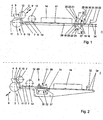
- Fig. 1 shows an apparatus which is suitable for carrying out the method, with their essential components for the invention.
- the device has a strand former 1.
- the strand former 1 consists essentially of two smooth rollers 2 and 3, which is preceded by a funnel 4 for receiving the mass 5 to be deformed.
- the mass is continuously fed or refilled by a device, not shown here in the hopper 5.
- the two rollers 2 and 3 together form an outlet gap 6, with the aid of which the mass 5 is drawn from the hopper 4 and deformed in the predetermined cross section, so that here a strand 7 is formed on a downstream of the strand former 1 driven conveyor belt. 8 is filed.
- an adjusting device is provided with the aid of which the gap width between the rollers 2 and 3 in the direction of a double arrow 9 is variable.
- the adjusting device may be associated with one or both of the rollers 2, 3, since with respect to the gap width, only the relative displacement of the rollers 2 and 3 relative to one another is important. It is also possible, for. B. only one of the rollers 2 or 3 to pivot in order to achieve a particularly sensitive change in the width of the exit gap 6.
- At least the roller 2 is driven according to arrow 10.
- the roller 3 is driven according to arrow 11.
- the adjusting device can be assigned to the drive of the rollers 2 and / or 3 at a constant or variable width of the exit slit 6.
- the formation speed is determined or determined, with which the mass 5 passes through the exit slit 6 and thus the strand 7 is formed.
- the initial cross section of the strand 7 is determined or determined.
- this drive speed of the rollers 2 and 3 and thus the formation speed is consistent with the drive speed of the conveyor belt 8.
- the formation of the cross section of the strand 7 in the region of the strand former 1 in conjunction with the conveyor belt 8 is thus influenced.
- the formation speed in the region of the strand former 1 does not necessarily have to match the drive speed of the conveyor belt 8. Again, differences between these two speeds depending on the nature of the mass may be useful or even necessary to place a uniform strand 7 with the provided, slightly stretched or compressed cross-section on the conveyor belt 8.
- the emerging from the exit slit 6 strand 7 will have a slightly greater height than corresponds to the desired product height.
- a driven calibrating roller 12 is usually used, which is employed in relation to the conveyor belt 8 supported in this area.
- the calibration roller 12 is driven in accordance with arrow 13 and serves to equalize the height of the strand 7.
- the mass 5 of the strand 7 also has compressible components, so that a certain compression of the strand 7 occurs or at least can occur due to the action of the calibrating roller 12.
- a tempering channel 14 can furthermore be provided, with the aid of which the strand 7 is tempered during the passage, ie cooled or heated.
- the arrangement point of the tempering channel 14 can also take place before the calibrating roller 12. It depends on the type and properties of the mass 5 or of the strand 7.
- the conveyor belt 8 is guided around deflection rollers 15 and 16 and is driven according to arrow 17, so that the resting on the surface of the conveyor belt 8 strand 7 is also conveyed away according to arrow 17.
- a further conveyor belt 18 is provided.
- the beginning of the conveyor belt 18 is guided around the deflection roller 19.
- the conveyor belt 18 is driven in the same direction as the conveyor belt 8.
- the drive speed of the conveyor belts 8 and 18 can be the same, but also selected or set differently.
- an interruption point 20 is formed between the end of the conveyor belt 8 and the beginning of the conveyor belt 18.
- the length of the point of interruption in the conveying direction according to arrow 17 is determined here by the distance between the deflection rollers 16 and 19.
- the strand 7 is conveyed freely suspended.
- two embossing units 21 and 22 are provided, the task of which is to act on the shaping of the surface of the strand 7. It is about the strand 7 at this point already subdivide in the longitudinal direction, so to design and transform individual product strands with respect to their cross-section.
- an embossing roller 23 is provided as embossing unit 21.
- the embossing unit 22 is formed by an embossing roller 24.
- the embossing roller 23 is driven about its axis 25 in the direction of the arrow 26. Accordingly, the embossing roller 24 is driven about its axis 27 in the direction of the arrow 28.
- the surface speed of the embossing rollers 23 and 24 is usually the same and also equal to the conveying speed of the strand 7 on the conveyor belt 8 is selected. In exceptional cases and in coordination with the properties of the mass 5 of the strand 7 but also different speeds can be useful.
- the embossing rollers 23 and 24 may be provided adjustable in their relative distance. The setting may be such that they touch one another or do not touch one another.
- the arrangement of the embossing rolls 23 and 24 preferably takes place in such a way that the strand 7 which is freely conveyed at the point of interruption 20 is deflected as little as possible out of the plane 29 in the middle of the height of the strand 7. It is understood that the plane 29 is provided horizontally aligned.
- the axes 25 and 27 of the two embossing rollers 23 and 24 are located in planes which are provided parallel to the plane 29 and in particular equidistant from this. But other arrangements are conceivable in which the axes 25 and 27 are arranged in any case in the vertical plane perpendicular to the conveying direction according to arrow 17. The arrangement depends in some cases on the cross-sectional profile of the products to be produced.
- a slitter 30 is provided in many cases, by means of which the contiguous, extending over the working width strand 7 is divided into individual product strands 31. This is the case in particular when the embossing rollers 23 and 24 do not perform a slitting function.
- the slitter 30 can also be arranged in front of the point of interruption and thus in front of the embossing rolls 23 and 24, and even before the tempering channel 14. In such cases, the individual product strands 31 are brought side by side over the working width in each case a small distance from each other and then formed by the embossing units 21, 22 circumferentially.
- a schematically illustrated cross cutter 32 is provided, which is driven according to double arrow 33 relative to the surface of the conveyor belt 18 and thereby dividing the product strands 31 into individual products 34. As a rule, this results in a plurality of row by row adjacent rows of products from the products 34.
- the products 34 have exactly the cross section, which has ultimately been formed by the embossing units 21, 22.
- the cross cutter 32 can work in such a way that the product strands 31 are completely severed, ie chopped. But it is also possible to dispense with a complete transection and formulate as it were only predetermined breaking points. In such cases, a downstream crushing device is then usually required.
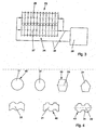
- FIG. 2 illustrated second embodiment of an apparatus for the continuous production of a product or more products 34 is similar in many areas constructed as the embodiment of Fig. 1 , so that it can be referenced.
- a common conveyor belt 35 is provided, which is guided around a number of pulleys in the manner shown and driven according to arrow 17.
- the embossing units 21 and 22 are formed here as a drawing nozzles 36 and 37, resiliently mounted and employed against each other.
- the drawing nozzles 36 and 37 can process the entire peripheral surface of the strand 7 and thus form the overall cross section.
- the drawing nozzles 36 and 37 can also fulfill a longitudinal cutting function, so that the strand 7 at the exit from the drawing nozzles 36 and 37 is subdivided into individual juxtaposed product strands 31 and the separate arrangement of a slitter becomes dispensable.
- a cross cutter 32 is also provided here, which divides the individual product strands 31 into individual products 34.
- the inlet of the product strands 31 in the tempering channel can be set lower than the inlet of the strand 7 in the drawing nozzles 36 and 37th
- Fig. 3 illustrates a section along the line III-III in Fig. 1 , So at the point of the two embossing rollers 23 and 24 at the point of interruption 20. It is here essentially the curved surface of the profile rollers 23 and 24 illustrates.
- the profile rollers 23 and 24 are made in contact with each other, so that these embossing units 21, 22 also perform longitudinal cutting function. It can be seen that the entire circumferential cross section of the strand or of the product strands that form is machined or shaped.
- the two embossing rollers 23 and 24 may be connected to a device 38 for tempering the embossing rollers 23 and 24.
- a circuit of corresponding line sections 39 is indicated schematically.
- Fig . 4 are possible cross sections 40 of product strands 31 shown, which are controllable by the method according to the invention and with the devices shown. It can be seen a circular cross-section, an ellipse-like cross-section, a hexagonal or pentagonal cross-section and wavy and indented cross-sections 40 in a symmetrical arrangement to the plane 29. But also designs over the width of constant thickness in corrugated shape are possible.
Landscapes
- Life Sciences & Earth Sciences (AREA)
- Engineering & Computer Science (AREA)
- Food Science & Technology (AREA)
- Chemical & Material Sciences (AREA)
- Polymers & Plastics (AREA)
- Confectionery (AREA)
- Manufacturing And Processing Devices For Dough (AREA)
Abstract
Description
Die Erfindung betrifft ein Verfahren zur kontinuierlichen Herstellung eines Produkts aus essbarer Masse, insbesondere Süßwarenmasse, indem aus der Masse ein Strang mit festgelegtem Querschnitt geformt wird, der Strang auf einem Transportband abgelegt und abgefördert wird und der Strang in einzelne Produkte zumindest quergeschnitten wird. Es wird auch eine Vorrichtung zur kontinuierlichen Herstellung eines Produkts aus essbarer Masse, insbesondere Süßwarenmasse, mit einem den Querschnitt der Masse bestimmenden Strangformer, einem angetriebenen Transportband zum Ablegen und Abfördern des von dem Strangformer gebildeten Strangs und zumindest einem Querschneider zum Unterteilen des Strangs in einzelne Produkte aufgezeigt.The invention relates to a method for the continuous production of a product from edible mass, in particular confectionery mass, by forming a strand of defined cross-section from the mass, the strand is deposited on a conveyor belt and conveyed away and the strand is at least cross-cut into individual products. There is also a device for the continuous production of a product of edible mass, in particular confectionery mass, with a cross section of the mass determining strand former, a driven conveyor belt for depositing and conveying the strand former formed by the strand former and at least one cross cutter for dividing the strand into individual products demonstrated.
Das Verfahren und die Vorrichtung dienen zur Herstellung von Produkten aus essbarer Masse, also insbesondere aus Süßwarenmasse und anderen Nahrungsmitteln. Die Massen sind flüssig bis pastös, also jedenfalls verformbar. Aus der verformbaren Masse wird zunächst ein Strang gebildet. Der Strang kann als Teppich oder Band über die Arbeitsbreite der Vorrichtung durchgehend erzeugt werden. Ein solcher durchgehender Strang wird dann längs und quer aufgeschnitten, so dass die einzelnen Produkte entstehen. Dabei handelt es sich in der Regel um Riegelware, also einzelne Produktstücke, die in der Regel im Horizontalschnitt etwa rechteckigen Umriss und im Vertikalschnitt quer zur Förderrichtung oft etwa quadratischen Querschnitt aufweisen. In Ausnahmefällen können auch Produkte mit im Horizontalschnitt kreisrunder oder abgerundeter Gestalt hergestellt werden, wenn das Längs- und Querschneiden durch eine Art Stanzvorgang erfolgt. Es ist aber auch möglich, den Strang von vornherein in Form mehrere separater Einzelstränge zu erzeugen, so dass auf das Längsschneiden verzichtet werden kann. Wenn in der vorliegenden Beschreibung von "Strang" die Rede ist, ist einerseits ein über die Arbeitsbreite reichender Gesamtstrang gemeint, der im Laufe der Formgebung in mehrere Produktstränge aufgeteilt, insbesondere längsgeschnitten, wird; andererseits kann von vornherein ein an einem Walzenformer gebildeter einzelner Produktstrang gemeint sein, der nur noch quergeschnitten werden muss.The method and the device are used for the production of products of edible mass, so in particular from confectionery mass and other foods. The masses are liquid to pasty, so in any case deformable. From the deformable mass, a strand is first formed. The strand can be continuously produced as a carpet or band across the working width of the device. Such a continuous strand is then cut longitudinally and transversely, so that the individual products arise. These are usually bar products, ie individual product pieces, which generally have approximately rectangular outline in the horizontal section and often approximately square in cross section perpendicular to the conveying direction. In exceptional cases, products can also be produced with a circular or rounded shape in horizontal section, if the longitudinal and transverse cutting takes place by a kind of punching process. But it is also possible to produce the strand from the outset in the form of several separate single strands, so that can be dispensed with the longitudinal cutting. When in the present description of "strand" is mentioned, on the one hand meant a reaching over the working width total strand, which is divided in the course of shaping into several product strands, in particular longitudinally cut, is; On the other hand, from the outset, a single product strand formed on a roll former may be meant, which only has to be cross-cut.
Der Strang bzw. der einzelne Produktstrang wird nach der Strangbildung, die über einen Strangformer erfolgt, auf einem angetriebenen Transportband abgelegt. Sowohl die Bildung des Strangs wie auch die Abförderung des Strangs auf dem Transportband werden kontinuierlich durchgeführt. Auf diese Weise können Produkte aus Nougat-, Karamell-, Fudge- oder ähnlichen Massen, die auch feste Stücke, z. B. gehackte Mandeln, Nüsse und dergleichen, enthalten, hergestellt werden. Ein wesentliches Anwendungsgebiet ist auch die Herstellung von Müsliriegeln, die als wesentliche Bestandteile Cerealien zumindest enthalten. Die Massen können auch belüftet sein oder komprimierbare Bestandteile enthalten. Die Produkte können auch weiche Süßwarenmasse, Fruchtmasse, Krokant, Toffee, aber auch hochgekochte Zuckermassen, Karamell, Fettmassen, Nougatcreme etc. enthalten.The strand or the individual product strand is deposited on a driven conveyor belt after strand formation, which takes place via a strand former. Both the formation of the strand as well as the removal of the strand on the conveyor belt are carried out continuously. In this way, products of nougat, caramel, fudge or similar masses, which also solid pieces, eg. As chopped almonds, nuts and the like, are produced. An essential field of application is also the production of cereal bars, which at least contain cereals as essential constituents. The masses may also be vented or contain compressible ingredients. The products may also contain soft confectionery mass, fruit pulp, brittle, toffee, but also high-boiled sugar masses, caramel, fat masses, nougat cream etc.
Ein Verfahren und eine Vorrichtung der eingangs beschriebenen Art sind bekannt. Zur Bildung des Strangs wird ein Strangformer eingesetzt, der zwei angetriebene Walzen mit glatter Oberfläche aufweist, die auf Abstand zueinander angeordnet sind und damit zwischen sich einen Spalt bilden, in den die formbare Masse eingezogen wird. Die Masse tritt dann in Form eines Teppichs (Strang) mit einer der Spaltweite entsprechenden Höhe aus dem Strangformer aus und wird so kontinuierlich auf ein angetriebenes Transportband abgelegt. Die Bildungsgeschwindigkeit des Strangs oder Teppichs am Austritt des Strangformers entspricht der Geschwindigkeit, mit der das Transportband angetrieben wird. Entsprechend der Spaltweite ergibt sich die Höhe des Strangs und damit letztendlich die gewünschte Strang- bzw. Produkthöhe eines z. B. hergestellten Riegels. Der Strang wird längs- und quergeschnitten, so dass auf diese Weise die Produkte entstehen.A method and a device of the type described above are known. To form the strand, a strand former is used, which has two driven rollers with a smooth surface, which are arranged at a distance to each other and thus form a gap between them, in which the moldable material is drawn. The mass then exits in the form of a carpet (strand) with a height corresponding to the gap width from the strand former and is thus deposited continuously on a driven conveyor belt. The rate of formation of the strand or carpet at the exit of the strand former corresponds to the speed at which the conveyor belt is driven. According to the gap width results in the height of the strand and thus ultimately the desired strand or product height of a z. B. produced bar. The strand is cut longitudinally and crosswise so that the products are formed in this way.
Je nach der Konsistenz, der Verarbeitungstemperatur, der Art der verarbeiteten Masse bzw. Massen sowie weiterer Parameter kann es erforderlich sein, einen oder mehrere Kühl- oder Temperierkanalabschnitte nach dem Walzenformer vorzusehen.Depending on the consistency, the processing temperature, the type of mass or mass processed and other parameters, it may be necessary to provide one or more cooling or Temperierkanalabschnitte after the roll former.
Auch die Anwendung einer Kalibrierwalze innerhalb der Vorrichtung ist bekannt. Eine solche Kalibrierwalze weist auch eine glatte Oberfläche auf und wirkt einseitig auf den Teppich bzw. Strang ein, um dessen Höhe zu vergleichmäßigen oder die gewünschte Höhe zu erreichen. Eine solche Kalibrierwalze wird gegen den auf dem Transportband abgeförderten Strang angestellt, wobei das Transportband entsprechend abgestützt ist.The use of a calibrating roller within the device is also known. Such a calibration roller also has a smooth surface and acts on one side of the carpet or strand to even out the height or reach the desired height. Such a calibration roller is employed against the conveyor belt conveyed off strand, wherein the conveyor belt is supported accordingly.
Es ist auch bereits bekannt, einer solchen Kalibrierwalze eine Prägewalze nachzuordnen. Die Prägewalze besitzt eine profilierte Oberfläche, mit der sie ähnlich wie eine Kalibrierwalze gegen den auf dem Transportband abgeförderten Strang angestellt wird. Während die Kalibrierwalze nur eine ebene Fläche an dem Strang formt, werden von einer Prägewalze weitere Bereiche der Oberfläche des Strangs bzw. der Produktstränge erfasst und umgeformt. Auf diese Weise können Strangbereiche oder Produktstränge mit etwa halbrundem Querschnitt in dem nach oben gekehrten Bereich geformt werden. Eine Beeinflussung der Formgebung des Bodens des Strangs oder Produktstrangs ist jedoch nicht möglich. Der Boden bleibt flach und eben. Seine Gestalt ergibt sich zwangsläufig durch die Auflage des Strangs auf dem Transportband. Produkte, die in ihrem vertikalen Querschnitt quer zur Förderrichtung kreisrunde, elliptische, sechseckige oder gewellte Gestalt aufweisen, sind auf diese Weise nicht herstellbar.It is also already known to arrange an embossing roller of such a calibration roller. The embossing roller has a profiled surface, with which it is employed in a manner similar to a sizing roll against the strand conveyed away on the conveyor belt. While the sizing roll only forms a flat surface on the strand, further regions of the surface of the strand or of the product strands are detected and reshaped by an embossing roll. In this way, strand areas or strands of product about semicircular cross-section can be formed in the upwardly swept area. However, an influence on the shape of the bottom of the strand or product strand is not possible. The floor remains flat and even. Its shape inevitably results from the circulation of the strand on the conveyor belt. Products which have in their vertical cross section transverse to the conveying direction circular, elliptical, hexagonal or corrugated shape, can not be produced in this way.
Der Erfindung liegt die Aufgabe zugrunde, ein Verfahren und eine Vorrichtung der eingangs beschriebenen Art aufzuzeigen, mit denen es möglich ist, Produkte herzustellen, die jedenfalls im Bereich des Bodens nicht-eben gestaltet sind. Die Produkte sollen in ihrem vertikalen Querschnitt quer zur Förderrichtung insbesondere kreisrunde, elliptische, sechseckige oder gewellte Gestalt aufweisen.The invention has for its object to provide a method and an apparatus of the type described above, with which it is possible to produce products that are not designed in any case in the field of soil. The products should have in their vertical cross section transverse to the conveying direction in particular circular, elliptical, hexagonal or corrugated shape.
Die Aufgabe der Erfindung wird erfindungsgemäß mit den Merkmalen der unabhängigen Patentansprüche 1 und 5 gelöst.The object of the invention is achieved according to the invention with the features of the
Bei dem erfindungsgemäßen Verfahren zur kontinuierlichen Herstellung eines Produktes aus essbarer Masse wird zunächst aus der Masse ein Strang mit festgelegtem Querschnitt geformt. Dies geschieht mit einem Strangformer. Der geformte Strang wird auf einem Transportband abgelegt und abgefördert. Der Strang wird in einzelne Produkte zerteilt, in der Regel also längs- und quergeschnitten. Der Strang wird über eine Unterbrechungsstelle des Transportbandes gefördert. Dabei bewegt sich der Strang über die Unterbrechungsstelle des Transportbandes hinweg. Während dieser Bewegung wird er zumindest von zwei Seiten geprägt und dabei nicht nur auf seine Oberfläche, sondern auch im Bereich des Bodens geformt. Die Prägung kann den gesamten Umfang, also die gesamte geschlossene Umfangslinie des Strangs bzw. des Produktstrangs umfassen, mit dem der Strang erzeugt wird, den also letztendlich auch das Produkt aufweisen soll. Es ist aber auch möglich, nur wesentliche Bestandteile der Umfangslinie beidseitig zu prägen und beispielsweise zusätzlich noch einen Längsschneider einzusetzen, um einen Strang in Produktstränge definitiv zu unterteilen. Das Längsscheiden kann vor oder nach dem Prägen erfolgen.In the method according to the invention for the continuous production of an edible mass product, a strand having a fixed cross section is first formed from the mass. This is done with a strand former. The shaped strand is deposited on a conveyor belt and conveyed away. The strand is divided into individual products, that is usually cut longitudinally and crosswise. The strand is conveyed via an interruption point of the conveyor belt. The strand moves over the point of interruption of the conveyor belt away. During this movement, it is shaped on at least two sides and shaped not only on its surface, but also in the area of the floor. The embossing may include the entire circumference, ie the entire closed circumferential line of the strand or of the product strand with which the strand is produced, that is to say ultimately also the product should have. But it is also possible to emboss on both sides only essential components of the circumference and, for example, additionally use a slitter to divide a strand in product strands definitely. The longitudinal shearing can be done before or after embossing.
Für die Bildung der Unterbrechungsstelle des Transportbandes stehen verschiedene Möglichkeiten zur Verfügung. Beispielsweise kann die Unterbrechungsstelle zwischen zwei einander zugeordneten und mit Abstand zueinander angeordneten Transportbändern gebildet sein. Es ist aber auch möglich, ein gemeinsames Transportband vorzusehen, welches zur Bildung der Unterbrechungsstelle entsprechend umgeleitet wird. Bei der zweiseitigen Prägung sollen insbesondere Bodenbereiche und nach oben gekehrte Oberflächenbereiche erreicht werden. Die Prägung wird in der Regel so durchgeführt werden, dass sie mehr oder weniger symmetrisch zu der Ebene erfolgt, die durch die Oberfläche des Transportbandes festgelegt ist.For the formation of the point of interruption of the conveyor belt, various options are available. For example, the point of interruption between two mutually associated and spaced conveyor belts may be formed. But it is also possible to provide a common conveyor belt, which is redirected to form the point of interruption accordingly. In the case of two-sided embossing, in particular floor areas and surface areas facing upwards are to be achieved. The embossing will usually be performed so that it is more or less symmetrical to the plane defined by the surface of the conveyor belt.
Wenn mit der beidseitigen Prägung die gesamte Umfangslinie des Querschnittes des Produktes gestaltet wird, kann damit gleichzeitig auch die Unterteilung des Strangs in einzelne Produktstränge erfolgen, so dass ein gesondertes Längsschneiden entbehrlich wird. Das Längsscheiden kann vor oder nach dem Prägen erfolgen. Es ist aber auch möglich, mit der beidseitigen Prägung nur einen Teil der Umfangslinie des Querschnittes des Produktes zu gestalten, wobei dann die definitive Trennung des Strangs in einzelne Produktstränge durch nachfolgendes Längsschneiden erfolgt.If the entire circumference of the cross section of the product is designed with the embossing on both sides, the subdivision of the strand into individual product strands can thus simultaneously take place, so that a separate longitudinal cutting becomes unnecessary. The longitudinal shearing can be done before or after embossing. But it is also possible to make with the embossing on both sides only a part of the peripheral line of the cross section of the product, in which case the definitive separation of the strand into individual product strands is carried out by subsequent longitudinal cutting.
Das Prägen kann insbesondere durch Walzen erfolgen, d. h. es handelt sich um einen Walzvorgang, bei dem walzen- oder trommelförmige Prägeelemente um Achsen rotierend angetrieben sind. Die Achsen sind in einer zur Förderrichtung senkrechten Ebene angeordnet. Es ist aber auch möglich, z. B. düsenartige Werkzeuge vorzusehen, mit deren Hilfe die gesamte Umfangslinie des Querschnittes der vorher gebildeten Produktstränge an der Unterbrechungsstelle umgeformt wird.The embossing can be done in particular by rolling, d. H. It is a rolling process in which roller or drum-shaped embossing elements are driven to rotate about axes. The axes are arranged in a plane perpendicular to the conveying direction. But it is also possible, for. B. nozzle-like tools provide, with the aid of which the entire circumference of the cross section of the previously formed product strands is formed at the point of interruption.
Eine Vorrichtung zur Durchführung des Verfahrens besitzt einen den Querschnitt der Masse als Strang bestimmenden Strangformer und ein angetriebenes Transportband zum Ablegen und Abfördern des von dem Strangformer gebildeten Strangs. In aller Regel ist auch zumindest ein Querschneider zum Unterteilen des Strangs in einzelne Produkte vorgesehen. Weitere Bestandteile der Vorrichtung können Kühlkanalabschnitte und/oder ein Längsschneider sein. Im Bereich des Transportbandes ist auf jeden Fall eine Unterbrechungsstelle gebildet, an der der abgelegte Strang von dem Transportband nicht unmittelbar abgestützt wird. Der Strang wird vielmehr freihängend über die Unterbrechungsstelle gefördert. Dabei greifen an dem Strang im Bereich der Unterbrechungsstelle mindestens zwei einander ergänzende Prägeeinheiten an, mit denen der Querschnitt des Strangs umgeformt wird. Die Umformung geschieht am frei geförderten Strang. Für die Ausbildung der Unterbrechungsstelle einerseits und-der Prägeeinheiten andererseits ergeben sich für den Fachmann verschiedene Möglichkeiten. So können die Prägeeinheiten als Prägebänder ausgebildet sein, die umlaufend angetrieben und geführt sind. Eine besonders einfache und wirkungsvolle Realisierungsmöglichkeit ergibt sich durch rotierend angetriebene Walzen, deren Oberflächen entsprechend profiliert ausgebildet sein. In aller Regel wird es sich dabei um nutenartige umlaufende Vertiefungen auf der Oberfläche der Walzen handeln, beispielsweise um halbkreisförmige Vertiefungen, wenn Produktstränge mit kreisrundem Querschnitt erzeugt werden sollen. Es ist eine Vielzahl von Formgebungen und Querschnittsgestaltungen möglich. So sind ovale, elliptische, rechteckig abgerundete, fünfeckige, sechseckige oder ähnliche Querschnitte möglich. Auch bandförmige Querschnitte in V- bzw. W-Form sind ohne weiteres möglich. Entsprechend sind die Walzen der Prägeeinheiten auf ihren Oberflächen profiliert.An apparatus for carrying out the method has a strand former which determines the cross-section of the mass as a strand and a driven conveyor belt for depositing and discharging the strand formed by the strand former. As a rule, at least one cross cutter for dividing the strand is provided in individual products. Further components of the device may be cooling duct sections and / or a longitudinal cutter. In the region of the conveyor belt, an interruption point is formed in any case, at which the deposited strand is not directly supported by the conveyor belt. Instead, the strand is conveyed freely suspended over the point of interruption. In this case, at least two mutually complementary embossing units engage with the strand in the region of the point of interruption, with which the cross section of the strand is reshaped. The forming takes place on the freely conveyed strand. For the formation of the point of interruption on the one hand and the embossing units on the other hand, various possibilities arise for the skilled person. Thus, the embossing units may be formed as embossing bands, which are driven and guided circumferentially. A particularly simple and effective realization possibility results from rotationally driven rollers whose surfaces are profiled profiled accordingly. As a rule, these will be groove-like circumferential depressions on the surface of the rolls, for example around semicircular depressions, if product strands with a circular cross-section are to be produced. It is a variety of shapes and cross-sectional shapes possible. So oval, elliptical, rectangular rounded, pentagonal, hexagonal or similar cross sections are possible. Also band-shaped cross sections in V- or W-shape are readily possible. Accordingly, the rollers of the embossing units are profiled on their surfaces.
Die Prägeeinheiten weisen Achsen auf, die bevorzugt in der zu der Ebene des Transportbandes parallelen Ebenen angeordnet sind. Die Prägewalzen können oben und unten, jeweils relativ zu der von dem Transportband auf der Oberfläche aufgespannten Ebene angeordnet sein. Die Prägewalzen können gleiche oder ungleiche Profile auf ihren Oberflächen besitzen, aus denen dann die Querschnittsform des jeweiligen Produktstrangs gebildet wird. Die Prägeeinheiten in Form angetriebener Walzen können gleiche oder ungleiche Durchmesser aufweisen. Die Profilierung in Umfangsrichtung kann konstant oder nicht konstant ausgebildet sein. Beispielsweise ist es auf diese Weise möglich, in die Produktstränge Kerben oder Sollbruchstellen einzuformen, mit deren Hilfe eine leichtere Unterteilung des Produktstrangs in die einzelnen Produkte möglich ist. Unter Umständen kann auf eine gesonderte Querschneidestation in diesem Zusammenhang verzichtet werden. Diese aufgezeigten Möglichkeiten sind jedoch stark von der Art der Masse, ihrer Konsistenz sowie weiteren Parametern abhängig und können im Einzelfall entsprechend angepasst und gewählt werden. Auch der Abstand der Prägeeinheiten zueinander kann einstellbar ausgebildet sein, um eine Längsschneidefunktion mehr oder weniger zu verwirklichen. In der Regel werden die Prägeeinheiten in Form angetriebener Walzen mit einer Oberflächen- bzw. Umfangsgeschwindigkeit angetrieben, die der Fördergeschwindigkeit des Strangs auf dem Transportband entspricht. Es ist jedoch ohne weiteres möglich, die Geschwindigkeiten der Oberflächen der Prägeeinheit auch abweichend davon festzulegen bzw. einzustellen. Dies gilt auch im Verhältnis zur Geschwindigkeit des Transportbandes.The embossing units have axes, which are preferably arranged in the plane parallel to the plane of the conveyor belt planes. The embossing rollers can be arranged above and below, in each case relative to the plane spanned by the conveyor belt on the surface. The embossing rollers may have the same or unequal profiles on their surfaces, from which then the cross-sectional shape of the respective product strand is formed. The embossing units in the form of driven rollers may have the same or different diameters. The profiling in the circumferential direction can be constant or not constant. For example, it is possible in this way to form notches or predetermined breaking points in the product strands, with the aid of which an easier subdivision of the product strand into the individual products is possible. Under certain circumstances can be dispensed with a separate cross-cutting station in this context. However, these options are highly dependent on the type of mass, their consistency and other parameters and can be adjusted and selected in each case. Also, the distance of the embossing units to each other can be designed to be adjustable in order to realize a longitudinal cutting function more or less. In general, the embossing units are driven in the form of driven rollers with a surface or peripheral speed corresponding to the conveying speed of the strand on the conveyor belt. However, it is readily possible to set or set the speeds of the surfaces of the embossing unit deviating therefrom. This also applies in relation to the speed of the conveyor belt.
Weiterhin können die Prägeeinheiten an einen Temperierkreislauf angeschlossen sein. Oft wird ein solcher Temperierkreislauf als Kühlkreislauf ausgebildet, um gleichzeitig mit der Prägung eine Reduzierung der Temperatur der warm verarbeiteten Massen zu erreichen. Es ist aber auch möglich, dass die Prägeeinheit eine Einrichtung zur Temperierung ihrer Oberflächen aufweist. In Einzelfällen muss es sich dabei sogar um eine Heizeinrichtung handeln. Wenn die in der Vorrichtung zu verarbeitenden Massen dies erfordern, kann sich auch die Reihenfolge der einzelnen Stationen in der Vorrichtung ändern. So ist es durchaus möglich, die durch die Prägeeinheiten gebildete Prägestation z. B. vor oder nach einem Kühlkanalabschnitt anzuordnen. Die Prägestation kann auch in unterschiedlicher Entfernung zu einer Querschneidestation vorgesehen sein. Falls die Prägeeinheit auch eine gewisse Querschneidefunktion erfüllt oder zumindest vorbereitet, kann die zusätzliche Anordnung von Querschneidestationen auch entfallen und/oder durch eine Brechstation ersetzt werden, wobei es der Gestalt der Produkte durchaus förderlich sein kann, wenn die in der Brechstation erzeugte Gestaltung unregelmäßig erfolgt, so dass eine gewisse Gestaltungsbreite, ähnlich einer Handarbeit, erreicht wird. In der Regel kann auf eine Querscheidestation nicht verzichtet werden.Furthermore, the embossing units can be connected to a temperature control. Often, such a tempering circuit is designed as a cooling circuit in order to simultaneously achieve a reduction in the temperature of the hot processed masses with the embossing. But it is also possible that the embossing unit has a device for tempering their surfaces. In some cases, it may even be a heating device. If the masses to be processed in the device require it, the order of the individual stations in the device may also change. So it is quite possible, the embossing unit formed by the embossing units z. B. to arrange before or after a cooling duct section. The embossing station can also be provided at different distances to a cross-cutting station. If the embossing unit also fulfills or at least prepares a certain cross-cutting function, the additional arrangement of cross-cutting stations can also be dispensed with and / or replaced by a breaking station, wherein the shape of the products can certainly be beneficial if the design produced in the breaking station is irregular, so that a certain range of design, similar to a manual work, is achieved. As a rule, a cross-separation station can not be dispensed with.
Im Folgenden wird die Erfindung anhand in den Figuren dargestellter bevorzugter Ausführungsbeispiele weiter erläutert und beschrieben.
- Fig. 1
- zeigt eine schematisierte Seitenansicht einer ersten Ausführungsform der Vorrichtung.
- Fig. 2
- zeigt eine schematisierte Seitenansicht einer zweiten Ausführungsform der Vorrichtung.
- Fig. 3
- zeigt eine Ansicht gemäß der Linie III-III in
Fig. 1 . - Fig. 4
- zeigt verschiedene mögliche Querschnitte von Produktsträngen bzw. Produkten.
- Fig. 1
- shows a schematic side view of a first embodiment of the device.
- Fig. 2
- shows a schematic side view of a second embodiment of the device.
- Fig. 3
- shows a view along the line III-III in
Fig. 1 , - Fig. 4
- shows various possible cross sections of product strands or products.
Zumindest die Walze 2 wird gemäß Pfeil 10 angetrieben. In der Regel wird auch die Walze 3 gemäß Pfeil 11 angetrieben. Die Stelleinrichtung kann bei konstanter oder auch bei veränderbarer Weite des Austrittsspalts 6 auch dem Antrieb der Walzen 2 und/oder 3 zugeordnet sein. Durch die Antriebsgeschwindigkeit der Walzen 2, 3 wird die Bildungsgeschwindigkeit festgelegt bzw. bestimmt, mit der die Masse 5 durch den Austrittsspalt 6 hindurchtritt und damit der Strang 7 gebildet wird. Damit wird der Anfangsquerschnitt des Strangs 7 festgelegt bzw. bestimmt. In der Regel stimmt diese Antriebsgeschwindigkeit der Walzen 2 und 3 und damit die Bildungsgeschwindigkeit mit der Antriebsgeschwindigkeit des Transportbandes 8 überein. Je nach der Konsistenz und den übrigen Eigenschaften, beispielsweise der Temperatur der Masse, wird so auf die Bildung des Querschnitts des Strangs 7 im Bereich des Strangsformers 1 in Verbindung mit dem Transportband 8 Einfluss genommen. Die Bildungsgeschwindigkeit im Bereich des Strangformers 1 muss jedoch nicht unbedingt mit der Antriebsgeschwindigkeit des Transportbandes 8 übereinstimmen. Auch hier können Unterschiede zwischen diesen beiden Geschwindigkeiten je nach der Art der Masse sinnvoll oder sogar erforderlich sein, um einen gleichmäßigen Strang 7 mit dem dazu vorgesehenen, geringfügig gedehnten oder gedrückten Querschnitt auf dem Transportband 8 abzulegen.At least the
In der-Regel wird der aus dem Austrittsspalt 6 austretende Strang 7 eine etwas größere Höhe aufweisen, als es der gewünschten Produkthöhe entspricht. Demzufolge wird auch in der Regel eine angetriebene Kalibrierwalze 12 eingesetzt, die gegenüber dem in diesem Bereich abgestützten Transportband 8 angestellt wird. Die Kalibrierwalze 12 wird gemäß Pfeil 13 angetrieben und dient dazu, die Höhe des Strangs 7 zu vergleichmäßigen. In der Regel besitzt die Masse 5 des Strangs 7 auch zusammendrückbare Bestandteile, so dass durch die Wirkung der Kalibrierwalze 12 eine gewisse Verdichtung des Strangs 7 eintritt oder zumindest eintreten kann. Im Bereich des Transportbandes 8 kann weiterhin ein Temperierkanal 14 vorgesehen sein, mit dessen Hilfe der Strang 7 beim Durchlauf temperiert, also gekühlt oder erwärmt wird. Die Anordnungsstelle des Temperierkanals 14 kann auch vor der Kalibrierwalze 12 erfolgen. Sie richtet sich nach der Art und den Eigenschaften der Masse 5 bzw. des Strangs 7.As a rule, the emerging from the exit slit 6
Das Transportband 8 ist um Umlenkrollen 15 und 16 geführt und wird gemäß Pfeil 17 angetrieben, so dass der auf der Oberfläche des Transportbandes 8 aufliegende Strang 7 auch gemäß Pfeil 17 abgefördert wird.The
In Relation zu dem Transportband 8 ist ein weiteres Transportband 18 vorgesehen. Der Anfang des Transportbandes 18 wird um die Umlenkrolle 19 geführt. Das Transportband 18 ist in gleicher Richtung wie das Transportband 8 angetrieben. Die Antriebsgeschwindigkeit der Transportbänder 8 und 18 kann gleich, aber auch unterschiedlich gewählt bzw. eingestellt werden.In relation to the
Zwischen dem Ende des Transportbandes 8 und dem Anfang des Transportbandes 18 ist eine Unterbrechungsstelle 20 gebildet. Die Länge der Unterbrechungsstelle in Förderrichtung gemäß Pfeil 17 wird hier durch den Abstand der Umlenkrollen 16 und 19 festgelegt. Im Bereich der Unterbrechungsstelle 20 wird der Strang 7 frei durchhängend gefördert. An der so gebildeten Unterbrechungsstelle 20 sind zwei Prägeeinheiten 21 und 22 vorgesehen, deren Aufgabe es ist, auf die Formgebung der Oberfläche des Strangs 7 einzuwirken. Dabei geht es darum, den Strang 7 an dieser Stelle bereits in Längsrichtung zu unterteilen, also einzelne Produktstränge hinsichtlich ihres Querschnittes zu gestalten und umzuformen. In dem in
Hinter den Prägeeinheiten 21, 22 und damit hinter der Unterbrechungsstelle 20 ist in vielen Fällen ein Längsschneider 30 vorgesehen, mit dessen Hilfe der zusammenhängende, sich über die Arbeitsbreite erstreckende Strang 7 in einzelne Produktstränge 31 unterteilt wird. Dies ist insbesondere dann der Fall, wenn die Prägewalzen 23 und 24 keine Längsschneidefunktion erfüllen. Der Längsschneider 30 kann aber auch vor der Unterbrechungsstelle und damit vor den Prägewalzen 23 und 24, ja sogar vor dem Temperierkanal 14 angeordnet sein. In solchen Fällen werden die einzelnen Produktstränge 31 nebeneinander über die Arbeitsbreite in jeweils geringfügigen Abstand zueinander gebracht und dann von den Prägeeinheiten 21, 22 umfangsmäßig umgeformt. Hinter dem Längsschneider 30 ist ein schematisch dargestellter Querschneider 32 vorgesehen, der gemäß Doppelpfeil 33 relativ zur Oberfläche des Transportbandes 18 angetrieben wird und dabei die Produktstränge 31 in einzelne Produkte 34 unterteilt. In der Regel ergeben sich damit mehrere reihenweise nebeneinander liegende Produktreihen aus den Produkten 34. Die Produkte 34 besitzen genau den Querschnitt, der letztlich durch die Prägeeinheiten 21, 22 geformt worden ist. Der Querschneider 32 kann so arbeiten, dass die Produktstränge 31 vollständig durchtrennt, also zerhackt, werden. Es ist aber auch möglich, auf eine vollständige Durchtrennung zu verzichten und gleichsam nur Sollbruchstellen einzuformen. In solchen Fällen wird dann in der Regel eine nachgeschaltete Brecheinrichtung erforderlich.Behind the
Das in
Weiterhin ist gegenüber dem Ausführungsbeispiel der
In
- 11
- Strangformerbatch former
- 22
- Walzeroller
- 33
- Walzeroller
- 44
- Trichterfunnel
- 55
- MasseDimensions
- 66
- Austrittsspaltexit slit
- 77
- Strangstrand
- 88th
- Transportbandconveyor belt
- 99
- Doppelpfeildouble arrow
- 1010
- Pfeilarrow
- 1111
- Pfeilarrow
- 1212
- Kalibrierwalzecalibrating
- 1313
- Pfeilarrow
- 1414
- Temperierkanaltempering
- 1515
- Umlenkrolleidler pulley
- 1616
- Umlenkrolleidler pulley
- 1717
- Pfeilarrow
- 1818
- Transportbandconveyor belt
- 1919
- Umlenkrolleidler pulley
- 2020
- Unterbrechungsstellebreakpoint
- 2121
- Prägeeinheitembossing unit
- 2222
- Prägeeinheitembossing unit
- 2323
- Prägewalzeembossing roller
- 2424
- Prägewalzeembossing roller
- 2525
- Achseaxis
- 2626
- Pfeilarrow
- 2727
- Achseaxis
- 2828
- Pfeilarrow
- 2929
- Ebenelevel
- 3030
- Längsschneiderslitter
- 3131
- Produktstrangproduct strand
- 3232
- QuerschneiderSheeter
- 3333
- Doppelpfeildouble arrow
- 3434
- Produktproduct
- 3535
- Transportbandconveyor belt
- 3636
- Ziehdüsedie
- 3737
- Ziehdüsedie
- 3838
- EinrichtungFacility
- 3939
- Leitungsabschnittline section
- 4040
- Querschnittcross-section
Claims (10)
- A method for the continuous production of a product of an eatable substance, especially a confectionery substance, comprising the steps of:forming the substance (5) into a slab (7) having a predetermined cross section,laying down the so formed slab (7) on the surface of a conveyor belt (8, 35) and transporting the formed slab (7) with the conveyor belt (8, 35),conveying the slab (7) over a point of break (20) of the conveyor belt (8, 18; 35) and embossing the slab (7) in the point of break (20) from two sides and thereby not only on its surface extending upwardly, but also in the region of its bottom, andfinally cutting the slab (7) at least transversely into the single products (34).
- The method of claim 1, characterized in that the entire circumference of the cross section (40) of the products (34) is formed by embossing from the two sides.
- The method of claim 1, characterized in that only a part of the circumference of the cross section (40) of the products (34) is formed by embossing from the two sides and in that the other shaping is performed by longitudinal slitting.
- The method of at least one of claims 1 to 3, characterized in that the embossing is performed by rolling.
- An apparatus for the continuous production of a product to be made from an eatable substance, especially a confectionery substance, including
a slab former (1) defining the cross section of the substance (5),
a driven conveyor belt (8) for laying down and transporting the slab (7) formed by the slab former (1), and at least a transverse cutter (32) for cutting the slab (7) into single products (34), especially of at least one of claims 1 to 4, characterized in that
a point of break (20) is formed in the region of the conveyor belt (8, 18; 35) and two cooperating embossing elements (21, 22) are provided there to deform the cross section of the slab (7) not only on its surface extending upwardly, but also in the region of its bottom. - The apparatus of claim 5, characterized in that rotationally driven embossing rollers (23, 24) are provided as the embossing elements (21, 22), the surfaces of the embossing rollers (23, 24) being profiled.
- The apparatus of at least one of claims 5 and 6, characterized in that the embossing elements (21, 22) have axes (25, 27) being arranged in planes being parallel to the plane of the conveyor belt (8, 35).
- The apparatus of at least one of claims 5 to 7, characterized in that the embossing elements (21, 22) comprise symmetrically profiled surfaces.
- The apparatus of at least one of claims 5 to 8, characterized in that the distance between the embossing elements (21, 22) is adjustable and/or the speeds of the surfaces of the embossing elements (21, 22) to each other and/or to the speed of the conveyor belt (8, 35) is settable.
- The apparatus of at least one of claims 5 to 9, characterized in that the embossing elements (21, 22) include a device (38) for tempering the surfaces.
Applications Claiming Priority (2)
| Application Number | Priority Date | Filing Date | Title |
|---|---|---|---|
| DE200410019795 DE102004019795C5 (en) | 2004-04-23 | 2004-04-23 | Method and apparatus for making a confectionery mass product |
| DE102004019795 | 2004-04-23 |
Publications (3)
| Publication Number | Publication Date |
|---|---|
| EP1588620A1 EP1588620A1 (en) | 2005-10-26 |
| EP1588620B1 EP1588620B1 (en) | 2007-05-16 |
| EP1588620B2 true EP1588620B2 (en) | 2013-11-20 |
Family
ID=34935493
Family Applications (1)
| Application Number | Title | Priority Date | Filing Date |
|---|---|---|---|
| EP05008696.6A Expired - Lifetime EP1588620B2 (en) | 2004-04-23 | 2005-04-21 | Process and apparatus for the preparation of a product based on a confectionery mass |
Country Status (3)
| Country | Link |
|---|---|
| EP (1) | EP1588620B2 (en) |
| DE (2) | DE102004019795C5 (en) |
| ES (1) | ES2285599T5 (en) |
Families Citing this family (5)
| Publication number | Priority date | Publication date | Assignee | Title |
|---|---|---|---|---|
| DK2712506T3 (en) | 2012-09-26 | 2016-12-05 | Sollich Kg | Roller forming device for forming a uniform blanket of confectionery mass |
| DE102014006658A1 (en) * | 2014-05-07 | 2015-11-12 | Hosokawa Bepex Gmbh | Apparatus for forming a uniform strand of a food mass |
| EP3837979B1 (en) * | 2019-12-18 | 2023-07-12 | Radie B.V. | Device for processing dough |
| CN112868691A (en) * | 2021-01-18 | 2021-06-01 | 王远清 | Shredded cake forming equipment |
| IT202100018062A1 (en) | 2021-07-08 | 2023-01-08 | Perfetti Van Melle Spa | APPARATUS FOR THE CREATION OF A CONFECTIONERY PRODUCT |
Citations (1)
| Publication number | Priority date | Publication date | Assignee | Title |
|---|---|---|---|---|
| US5516542A (en) † | 1991-03-04 | 1996-05-14 | General Mills, Inc. | Rolled food item fabricating methods |
Family Cites Families (6)
| Publication number | Priority date | Publication date | Assignee | Title |
|---|---|---|---|---|
| DE262490C (en) * | ||||
| DE394995C (en) * | 1922-04-14 | 1924-05-13 | Fritz Gessner | Candy machine for forming the sugar strand by means of stamps |
| DE516730C (en) * | 1929-10-08 | 1931-01-27 | Max Poenisch | Machine for the production of cream or similar caramels |
| DE3004022C2 (en) * | 1980-02-05 | 1987-01-22 | Sollich Gmbh & Co Kg, 4902 Bad Salzuflen | Device for dividing webs of deformable mass coming from a storage container into product strands |
| US4468186A (en) * | 1980-05-05 | 1984-08-28 | Sollich Kg, Spezialmaschinenfabrik | Apparatus for forming strands from moldable confectionary substance |
| DE10119077C1 (en) * | 2001-04-19 | 2002-11-28 | Sollich Kg | Method and device for the continuous provision of longitudinally and transversely cut confectionery pieces |
-
2004
- 2004-04-23 DE DE200410019795 patent/DE102004019795C5/en not_active Expired - Fee Related
-
2005
- 2005-04-21 ES ES05008696T patent/ES2285599T5/en not_active Expired - Lifetime
- 2005-04-21 DE DE200550000720 patent/DE502005000720D1/en not_active Expired - Lifetime
- 2005-04-21 EP EP05008696.6A patent/EP1588620B2/en not_active Expired - Lifetime
Patent Citations (1)
| Publication number | Priority date | Publication date | Assignee | Title |
|---|---|---|---|---|
| US5516542A (en) † | 1991-03-04 | 1996-05-14 | General Mills, Inc. | Rolled food item fabricating methods |
Non-Patent Citations (8)
| Title |
|---|
| Fotographien des in der an die Firma Beacon Sweets ausgelieferten Formpressmaschine eingesetzten Profil-Walzgeräts † |
| Propspekt der Firma Hosokawa Bepex GmbH betreffend Universal-Formpresssysteme † |
| Prospekt der Firma Hosokawa Bepex GmbH betreffend Schnellschneidemaschinen † |
| Seite 1 der Stückliste des in der an die Firma Beacon Sweets ausgelieferten Formpressmaschine eingesetzen Profil-Walzgeräts † |
| Technische Zeichnung einer von der Firma Bepex Hutt Engineering GmbH im Jahre 1980 an die Firma Hai Tai, Korea ausgelieferten Formpressmaschine † |
| Technische Zeichnung einer von der Firma Bepex Hutt Engineering GmbH im Jahre 1984 an die Firma Beacon Sweets, Südafrika ausgelieferten Formpressmachine † |
| Technische Zeichnung eines in der an die Firma Hai Tai ausgelieferten Formpressmaschine eingesetzten Profil-Walzgeräts † |
| Technische Zeichnungen eines in der an die Firma Beacon Sweets ausgelieferten Formpressmaschine eingesetzen Profil-Walzgeräts † |
Also Published As
| Publication number | Publication date |
|---|---|
| ES2285599T5 (en) | 2014-01-08 |
| ES2285599T3 (en) | 2007-11-16 |
| DE102004019795C5 (en) | 2011-12-22 |
| EP1588620B1 (en) | 2007-05-16 |
| EP1588620A1 (en) | 2005-10-26 |
| DE102004019795B3 (en) | 2006-01-05 |
| DE502005000720D1 (en) | 2007-06-28 |
Similar Documents
| Publication | Publication Date | Title |
|---|---|---|
| DE69421527T2 (en) | Method and device for producing filled dough products | |
| DE2632802A1 (en) | METHOD AND DEVICE FOR THE MANUFACTURING OF COMPONENTS | |
| EP3247214B1 (en) | Dough processing machine, method for preparing dough products with such a dough processing machine as well as their use, and pre-baked dough compound | |
| DE68910981T2 (en) | Manufacture of flakes. | |
| DE69706120T2 (en) | Device for forming pieces of bread dough or the like | |
| DE10338217B3 (en) | Continuous production of confectionery, by laying a shaped mass strand a conveyor belt and cutting into portions, with a weighing unit linked to a control to adjust parameters on a deviation from nominal weights | |
| EP2510791B1 (en) | Device for forming a sheet of dough from supplied dough portions | |
| EP1588620B2 (en) | Process and apparatus for the preparation of a product based on a confectionery mass | |
| EP2712506B1 (en) | Roller former for forming a uniform slab of confectionary mass | |
| DE10035461B4 (en) | Method and device for molding a confectionery mass | |
| AT507711B1 (en) | DEVICE FOR FORMING GILLBARS, IN PARTICULAR FROM A MEAT MASS | |
| EP0673200A1 (en) | Process and device for producing layered cakes | |
| EP0024716A1 (en) | Process and apparatus for producing block-shaped foodstuffs | |
| DE69028543T2 (en) | METHOD AND DEVICE FOR THE PRODUCTION OF EXTRUDED ICE CREAM PRODUCTS | |
| DE19917390C2 (en) | Device for processing a strand of dough | |
| EP0668016B1 (en) | Device for producing dough portions for rustic bread rolls | |
| DE4406102C2 (en) | Device for round and / or long kneading of dough | |
| DE2815804C3 (en) | Device for shaping masses used in confectionery production into mass strands | |
| DE3704665C2 (en) | Process and apparatus for the continuous production of spiral pasta | |
| DE3004022C2 (en) | Device for dividing webs of deformable mass coming from a storage container into product strands | |
| DE102004014249B4 (en) | Method and device for producing filled baked goods | |
| EP4066646B1 (en) | Dough conditioning device | |
| EP1614353A1 (en) | Device for supplying and forming of plastically deformable sweatmeat | |
| EP1020116A1 (en) | Production method and system for bread roll dough pieces | |
| DE2451326C3 (en) | Combined cutter and dough-forming system for the production of various types of pastry |
Legal Events
| Date | Code | Title | Description |
|---|---|---|---|
| PUAI | Public reference made under article 153(3) epc to a published international application that has entered the european phase |
Free format text: ORIGINAL CODE: 0009012 |
|
| 17P | Request for examination filed |
Effective date: 20050827 |
|
| AK | Designated contracting states |
Kind code of ref document: A1 Designated state(s): AT BE BG CH CY CZ DE DK EE ES FI FR GB GR HU IE IS IT LI LT LU MC NL PL PT RO SE SI SK TR |
|
| AX | Request for extension of the european patent |
Extension state: AL BA HR LV MK YU |
|
| AKX | Designation fees paid |
Designated state(s): DE ES FR GB NL |
|
| GRAP | Despatch of communication of intention to grant a patent |
Free format text: ORIGINAL CODE: EPIDOSNIGR1 |
|
| GRAS | Grant fee paid |
Free format text: ORIGINAL CODE: EPIDOSNIGR3 |
|
| GRAA | (expected) grant |
Free format text: ORIGINAL CODE: 0009210 |
|
| AK | Designated contracting states |
Kind code of ref document: B1 Designated state(s): DE ES FR GB NL |
|
| REG | Reference to a national code |
Ref country code: GB Ref legal event code: FG4D Free format text: NOT ENGLISH |
|
| GBT | Gb: translation of ep patent filed (gb section 77(6)(a)/1977) |
Effective date: 20070516 |
|
| REF | Corresponds to: |
Ref document number: 502005000720 Country of ref document: DE Date of ref document: 20070628 Kind code of ref document: P |
|
| ET | Fr: translation filed | ||
| REG | Reference to a national code |
Ref country code: ES Ref legal event code: FG2A Ref document number: 2285599 Country of ref document: ES Kind code of ref document: T3 |
|
| PLBI | Opposition filed |
Free format text: ORIGINAL CODE: 0009260 |
|
| 26 | Opposition filed |
Opponent name: HOSOKAWA BEPEX GMBH Effective date: 20080213 |
|
| PLAX | Notice of opposition and request to file observation + time limit sent |
Free format text: ORIGINAL CODE: EPIDOSNOBS2 |
|
| PLBB | Reply of patent proprietor to notice(s) of opposition received |
Free format text: ORIGINAL CODE: EPIDOSNOBS3 |
|
| NLR1 | Nl: opposition has been filed with the epo |
Opponent name: HOSOKAWA BEPEX GMBH |
|
| RIC2 | Information provided on ipc code assigned after grant |
Ipc: A21C 3/02 20060101AFI20130111BHEP Ipc: A21C 11/12 20060101ALI20130111BHEP Ipc: A21C 3/10 20060101ALI20130111BHEP Ipc: A23G 3/12 20060101ALI20130111BHEP Ipc: A23G 3/00 20060101ALI20130111BHEP Ipc: A23G 3/06 20060101ALI20130111BHEP Ipc: A21C 11/10 20060101ALI20130111BHEP Ipc: A23G 3/02 20060101ALI20130111BHEP |
|
| PGFP | Annual fee paid to national office [announced via postgrant information from national office to epo] |
Ref country code: GB Payment date: 20130422 Year of fee payment: 9 |
|
| PGFP | Annual fee paid to national office [announced via postgrant information from national office to epo] |
Ref country code: FR Payment date: 20130523 Year of fee payment: 9 |
|
| PUAH | Patent maintained in amended form |
Free format text: ORIGINAL CODE: 0009272 |
|
| STAA | Information on the status of an ep patent application or granted ep patent |
Free format text: STATUS: PATENT MAINTAINED AS AMENDED |
|
| 27A | Patent maintained in amended form |
Effective date: 20131120 |
|
| AK | Designated contracting states |
Kind code of ref document: B2 Designated state(s): DE ES FR GB NL |
|
| REG | Reference to a national code |
Ref country code: ES Ref legal event code: DC2A Ref document number: 2285599 Country of ref document: ES Kind code of ref document: T5 Effective date: 20140108 |
|
| REG | Reference to a national code |
Ref country code: DE Ref legal event code: R102 Ref document number: 502005000720 Country of ref document: DE Effective date: 20131120 |
|
| REG | Reference to a national code |
Ref country code: NL Ref legal event code: T3 |
|
| GBPC | Gb: european patent ceased through non-payment of renewal fee |
Effective date: 20140421 |
|
| REG | Reference to a national code |
Ref country code: FR Ref legal event code: ST Effective date: 20141231 |
|
| PG25 | Lapsed in a contracting state [announced via postgrant information from national office to epo] |
Ref country code: GB Free format text: LAPSE BECAUSE OF NON-PAYMENT OF DUE FEES Effective date: 20140421 |
|
| PG25 | Lapsed in a contracting state [announced via postgrant information from national office to epo] |
Ref country code: FR Free format text: LAPSE BECAUSE OF NON-PAYMENT OF DUE FEES Effective date: 20140430 |
|
| PGFP | Annual fee paid to national office [announced via postgrant information from national office to epo] |
Ref country code: NL Payment date: 20160422 Year of fee payment: 12 |
|
| PGFP | Annual fee paid to national office [announced via postgrant information from national office to epo] |
Ref country code: ES Payment date: 20160422 Year of fee payment: 12 |
|
| REG | Reference to a national code |
Ref country code: NL Ref legal event code: MM Effective date: 20170501 |
|
| PG25 | Lapsed in a contracting state [announced via postgrant information from national office to epo] |
Ref country code: NL Free format text: LAPSE BECAUSE OF NON-PAYMENT OF DUE FEES Effective date: 20170501 |
|
| REG | Reference to a national code |
Ref country code: ES Ref legal event code: FD2A Effective date: 20180705 |
|
| PG25 | Lapsed in a contracting state [announced via postgrant information from national office to epo] |
Ref country code: ES Free format text: LAPSE BECAUSE OF NON-PAYMENT OF DUE FEES Effective date: 20170422 |
|
| PGFP | Annual fee paid to national office [announced via postgrant information from national office to epo] |
Ref country code: DE Payment date: 20220202 Year of fee payment: 18 |
|
| REG | Reference to a national code |
Ref country code: DE Ref legal event code: R119 Ref document number: 502005000720 Country of ref document: DE |
|
| PG25 | Lapsed in a contracting state [announced via postgrant information from national office to epo] |
Ref country code: DE Free format text: LAPSE BECAUSE OF NON-PAYMENT OF DUE FEES Effective date: 20231103 |