EP1588018B1 - Datenübertragungssystem für ein tiefbohrelement - Google Patents
Datenübertragungssystem für ein tiefbohrelement Download PDFInfo
- Publication number
- EP1588018B1 EP1588018B1 EP04703847A EP04703847A EP1588018B1 EP 1588018 B1 EP1588018 B1 EP 1588018B1 EP 04703847 A EP04703847 A EP 04703847A EP 04703847 A EP04703847 A EP 04703847A EP 1588018 B1 EP1588018 B1 EP 1588018B1
- Authority
- EP
- European Patent Office
- Prior art keywords
- conductive
- conductive tube
- wire
- coaxial cable
- passages
- Prior art date
- Legal status (The legal status is an assumption and is not a legal conclusion. Google has not performed a legal analysis and makes no representation as to the accuracy of the status listed.)
- Expired - Lifetime
Links
- 230000005540 biological transmission Effects 0.000 title abstract description 17
- 238000004891 communication Methods 0.000 claims description 68
- 239000000463 material Substances 0.000 claims description 28
- 238000000034 method Methods 0.000 claims description 25
- 229910000831 Steel Inorganic materials 0.000 claims description 22
- 239000010959 steel Substances 0.000 claims description 22
- 230000001965 increasing effect Effects 0.000 claims description 21
- 229910052751 metal Inorganic materials 0.000 claims description 17
- 239000002184 metal Substances 0.000 claims description 17
- 230000001939 inductive effect Effects 0.000 claims description 16
- 229910000859 α-Fe Inorganic materials 0.000 claims description 16
- 239000004020 conductor Substances 0.000 claims description 14
- 229920001343 polytetrafluoroethylene Polymers 0.000 claims description 10
- 239000004810 polytetrafluoroethylene Substances 0.000 claims description 10
- 239000004593 Epoxy Substances 0.000 claims description 9
- 239000003989 dielectric material Substances 0.000 claims description 9
- 239000012777 electrically insulating material Substances 0.000 claims description 7
- 230000000717 retained effect Effects 0.000 claims description 5
- 229920001774 Perfluoroether Polymers 0.000 claims description 4
- 230000014759 maintenance of location Effects 0.000 claims description 4
- -1 polytetrafluoroethylene Polymers 0.000 claims description 4
- 239000011152 fibreglass Substances 0.000 claims description 3
- 229920001973 fluoroelastomer Polymers 0.000 claims description 3
- 238000003780 insertion Methods 0.000 claims description 3
- 230000037431 insertion Effects 0.000 claims description 3
- 229920002635 polyurethane Polymers 0.000 claims description 3
- 239000004814 polyurethane Substances 0.000 claims description 3
- 229920001971 elastomer Polymers 0.000 claims description 2
- 239000011810 insulating material Substances 0.000 claims 2
- 230000005291 magnetic effect Effects 0.000 abstract description 30
- 238000012986 modification Methods 0.000 abstract description 2
- 230000004048 modification Effects 0.000 abstract description 2
- 230000035699 permeability Effects 0.000 description 15
- 238000005553 drilling Methods 0.000 description 9
- 239000003921 oil Substances 0.000 description 8
- 239000004696 Poly ether ether ketone Substances 0.000 description 6
- 229920002530 polyetherether ketone Polymers 0.000 description 6
- 229920000642 polymer Polymers 0.000 description 6
- RYGMFSIKBFXOCR-UHFFFAOYSA-N Copper Chemical compound [Cu] RYGMFSIKBFXOCR-UHFFFAOYSA-N 0.000 description 5
- UQSXHKLRYXJYBZ-UHFFFAOYSA-N Iron oxide Chemical compound [Fe]=O UQSXHKLRYXJYBZ-UHFFFAOYSA-N 0.000 description 5
- 230000008901 benefit Effects 0.000 description 5
- JUPQTSLXMOCDHR-UHFFFAOYSA-N benzene-1,4-diol;bis(4-fluorophenyl)methanone Chemical compound OC1=CC=C(O)C=C1.C1=CC(F)=CC=C1C(=O)C1=CC=C(F)C=C1 JUPQTSLXMOCDHR-UHFFFAOYSA-N 0.000 description 5
- 230000015572 biosynthetic process Effects 0.000 description 5
- 239000011248 coating agent Substances 0.000 description 5
- 238000000576 coating method Methods 0.000 description 5
- 238000004519 manufacturing process Methods 0.000 description 5
- XEEYBQQBJWHFJM-UHFFFAOYSA-N Iron Chemical compound [Fe] XEEYBQQBJWHFJM-UHFFFAOYSA-N 0.000 description 4
- 229910052802 copper Inorganic materials 0.000 description 4
- 239000010949 copper Substances 0.000 description 4
- 238000013461 design Methods 0.000 description 4
- 239000011159 matrix material Substances 0.000 description 4
- 230000007423 decrease Effects 0.000 description 3
- 238000009413 insulation Methods 0.000 description 3
- 239000012212 insulator Substances 0.000 description 3
- 239000010935 stainless steel Substances 0.000 description 3
- 229910001220 stainless steel Inorganic materials 0.000 description 3
- LVGUZGTVOIAKKC-UHFFFAOYSA-N 1,1,1,2-tetrafluoroethane Chemical compound FCC(F)(F)F LVGUZGTVOIAKKC-UHFFFAOYSA-N 0.000 description 2
- PXHVJJICTQNCMI-UHFFFAOYSA-N Nickel Chemical compound [Ni] PXHVJJICTQNCMI-UHFFFAOYSA-N 0.000 description 2
- 239000004809 Teflon Substances 0.000 description 2
- 229920006362 Teflon® Polymers 0.000 description 2
- 229910001315 Tool steel Inorganic materials 0.000 description 2
- 238000005299 abrasion Methods 0.000 description 2
- 230000003466 anti-cipated effect Effects 0.000 description 2
- 239000000919 ceramic Substances 0.000 description 2
- 230000008859 change Effects 0.000 description 2
- 230000008878 coupling Effects 0.000 description 2
- 238000010168 coupling process Methods 0.000 description 2
- 238000005859 coupling reaction Methods 0.000 description 2
- 210000003298 dental enamel Anatomy 0.000 description 2
- 239000000945 filler Substances 0.000 description 2
- 229920005570 flexible polymer Polymers 0.000 description 2
- 238000009472 formulation Methods 0.000 description 2
- 230000005251 gamma ray Effects 0.000 description 2
- 229920001903 high density polyethylene Polymers 0.000 description 2
- 239000004700 high-density polyethylene Substances 0.000 description 2
- 238000007373 indentation Methods 0.000 description 2
- 229910052742 iron Inorganic materials 0.000 description 2
- 239000007788 liquid Substances 0.000 description 2
- 150000002739 metals Chemical class 0.000 description 2
- 239000000203 mixture Substances 0.000 description 2
- TWNQGVIAIRXVLR-UHFFFAOYSA-N oxo(oxoalumanyloxy)alumane Chemical compound O=[Al]O[Al]=O TWNQGVIAIRXVLR-UHFFFAOYSA-N 0.000 description 2
- 239000002245 particle Substances 0.000 description 2
- 239000011148 porous material Substances 0.000 description 2
- 230000001681 protective effect Effects 0.000 description 2
- 125000006850 spacer group Chemical group 0.000 description 2
- 239000002966 varnish Substances 0.000 description 2
- 229910000851 Alloy steel Inorganic materials 0.000 description 1
- 229920000049 Carbon (fiber) Polymers 0.000 description 1
- 229910000976 Electrical steel Inorganic materials 0.000 description 1
- 229920002449 FKM Polymers 0.000 description 1
- 244000043261 Hevea brasiliensis Species 0.000 description 1
- FYYHWMGAXLPEAU-UHFFFAOYSA-N Magnesium Chemical compound [Mg] FYYHWMGAXLPEAU-UHFFFAOYSA-N 0.000 description 1
- VYPSYNLAJGMNEJ-UHFFFAOYSA-N Silicium dioxide Chemical compound O=[Si]=O VYPSYNLAJGMNEJ-UHFFFAOYSA-N 0.000 description 1
- XUIMIQQOPSSXEZ-UHFFFAOYSA-N Silicon Chemical compound [Si] XUIMIQQOPSSXEZ-UHFFFAOYSA-N 0.000 description 1
- 229920006172 Tetrafluoroethylene propylene Polymers 0.000 description 1
- 229920004695 VICTREX™ PEEK Polymers 0.000 description 1
- 229910045601 alloy Inorganic materials 0.000 description 1
- 239000000956 alloy Substances 0.000 description 1
- 229910052782 aluminium Inorganic materials 0.000 description 1
- XAGFODPZIPBFFR-UHFFFAOYSA-N aluminium Chemical compound [Al] XAGFODPZIPBFFR-UHFFFAOYSA-N 0.000 description 1
- 230000003321 amplification Effects 0.000 description 1
- 125000003118 aryl group Chemical group 0.000 description 1
- 230000002238 attenuated effect Effects 0.000 description 1
- 229910052788 barium Inorganic materials 0.000 description 1
- DSAJWYNOEDNPEQ-UHFFFAOYSA-N barium atom Chemical compound [Ba] DSAJWYNOEDNPEQ-UHFFFAOYSA-N 0.000 description 1
- 230000009286 beneficial effect Effects 0.000 description 1
- 238000009530 blood pressure measurement Methods 0.000 description 1
- 239000004917 carbon fiber Substances 0.000 description 1
- 238000012512 characterization method Methods 0.000 description 1
- 238000006243 chemical reaction Methods 0.000 description 1
- 229910017052 cobalt Inorganic materials 0.000 description 1
- 239000010941 cobalt Substances 0.000 description 1
- GUTLYIVDDKVIGB-UHFFFAOYSA-N cobalt atom Chemical compound [Co] GUTLYIVDDKVIGB-UHFFFAOYSA-N 0.000 description 1
- 239000002131 composite material Substances 0.000 description 1
- 238000007906 compression Methods 0.000 description 1
- 230000006835 compression Effects 0.000 description 1
- 238000012937 correction Methods 0.000 description 1
- 238000005260 corrosion Methods 0.000 description 1
- 230000007797 corrosion Effects 0.000 description 1
- 239000013078 crystal Substances 0.000 description 1
- 230000003247 decreasing effect Effects 0.000 description 1
- 238000011161 development Methods 0.000 description 1
- 230000000694 effects Effects 0.000 description 1
- 230000005684 electric field Effects 0.000 description 1
- 238000005516 engineering process Methods 0.000 description 1
- 230000005294 ferromagnetic effect Effects 0.000 description 1
- 239000000835 fiber Substances 0.000 description 1
- 230000004907 flux Effects 0.000 description 1
- 229910021485 fumed silica Inorganic materials 0.000 description 1
- 230000006698 induction Effects 0.000 description 1
- 229910052500 inorganic mineral Inorganic materials 0.000 description 1
- 238000009434 installation Methods 0.000 description 1
- JEIPFZHSYJVQDO-UHFFFAOYSA-N iron(III) oxide Inorganic materials O=[Fe]O[Fe]=O JEIPFZHSYJVQDO-UHFFFAOYSA-N 0.000 description 1
- 238000003475 lamination Methods 0.000 description 1
- 229910052749 magnesium Inorganic materials 0.000 description 1
- 239000011777 magnesium Substances 0.000 description 1
- 230000005381 magnetic domain Effects 0.000 description 1
- 239000000696 magnetic material Substances 0.000 description 1
- WPBNNNQJVZRUHP-UHFFFAOYSA-L manganese(2+);methyl n-[[2-(methoxycarbonylcarbamothioylamino)phenyl]carbamothioyl]carbamate;n-[2-(sulfidocarbothioylamino)ethyl]carbamodithioate Chemical compound [Mn+2].[S-]C(=S)NCCNC([S-])=S.COC(=O)NC(=S)NC1=CC=CC=C1NC(=S)NC(=O)OC WPBNNNQJVZRUHP-UHFFFAOYSA-L 0.000 description 1
- 239000002923 metal particle Substances 0.000 description 1
- VNWKTOKETHGBQD-UHFFFAOYSA-N methane Chemical compound C VNWKTOKETHGBQD-UHFFFAOYSA-N 0.000 description 1
- 239000010445 mica Substances 0.000 description 1
- 229910052618 mica group Inorganic materials 0.000 description 1
- 239000011707 mineral Substances 0.000 description 1
- 229920003052 natural elastomer Polymers 0.000 description 1
- 229920001194 natural rubber Polymers 0.000 description 1
- 229910052759 nickel Inorganic materials 0.000 description 1
- 238000003199 nucleic acid amplification method Methods 0.000 description 1
- NDLPOXTZKUMGOV-UHFFFAOYSA-N oxo(oxoferriooxy)iron hydrate Chemical compound O.O=[Fe]O[Fe]=O NDLPOXTZKUMGOV-UHFFFAOYSA-N 0.000 description 1
- 239000012256 powdered iron Substances 0.000 description 1
- 239000012254 powdered material Substances 0.000 description 1
- 238000004321 preservation Methods 0.000 description 1
- 230000001737 promoting effect Effects 0.000 description 1
- 239000012858 resilient material Substances 0.000 description 1
- 229920005989 resin Polymers 0.000 description 1
- 239000011347 resin Substances 0.000 description 1
- 238000009420 retrofitting Methods 0.000 description 1
- 238000007789 sealing Methods 0.000 description 1
- 230000008054 signal transmission Effects 0.000 description 1
- 229910052710 silicon Inorganic materials 0.000 description 1
- 239000010703 silicon Substances 0.000 description 1
- 229910052709 silver Inorganic materials 0.000 description 1
- 239000004332 silver Substances 0.000 description 1
- 239000000126 substance Substances 0.000 description 1
- 238000012360 testing method Methods 0.000 description 1
- BFKJFAAPBSQJPD-UHFFFAOYSA-N tetrafluoroethene Chemical compound FC(F)=C(F)F BFKJFAAPBSQJPD-UHFFFAOYSA-N 0.000 description 1
- 229920001169 thermoplastic Polymers 0.000 description 1
- 238000012546 transfer Methods 0.000 description 1
- 230000007704 transition Effects 0.000 description 1
- 150000003673 urethanes Chemical class 0.000 description 1
- XLYOFNOQVPJJNP-UHFFFAOYSA-N water Substances O XLYOFNOQVPJJNP-UHFFFAOYSA-N 0.000 description 1
Images



Classifications
-
- F—MECHANICAL ENGINEERING; LIGHTING; HEATING; WEAPONS; BLASTING
- F16—ENGINEERING ELEMENTS AND UNITS; GENERAL MEASURES FOR PRODUCING AND MAINTAINING EFFECTIVE FUNCTIONING OF MACHINES OR INSTALLATIONS; THERMAL INSULATION IN GENERAL
- F16L—PIPES; JOINTS OR FITTINGS FOR PIPES; SUPPORTS FOR PIPES, CABLES OR PROTECTIVE TUBING; MEANS FOR THERMAL INSULATION IN GENERAL
- F16L15/00—Screw-threaded joints; Forms of screw-threads for such joints
- F16L15/001—Screw-threaded joints; Forms of screw-threads for such joints with conical threads
- F16L15/003—Screw-threaded joints; Forms of screw-threads for such joints with conical threads with sealing rings
-
- E—FIXED CONSTRUCTIONS
- E21—EARTH OR ROCK DRILLING; MINING
- E21B—EARTH OR ROCK DRILLING; OBTAINING OIL, GAS, WATER, SOLUBLE OR MELTABLE MATERIALS OR A SLURRY OF MINERALS FROM WELLS
- E21B17/00—Drilling rods or pipes; Flexible drill strings; Kellies; Drill collars; Sucker rods; Cables; Casings; Tubings
- E21B17/003—Drilling rods or pipes; Flexible drill strings; Kellies; Drill collars; Sucker rods; Cables; Casings; Tubings with electrically conducting or insulating means
-
- E—FIXED CONSTRUCTIONS
- E21—EARTH OR ROCK DRILLING; MINING
- E21B—EARTH OR ROCK DRILLING; OBTAINING OIL, GAS, WATER, SOLUBLE OR MELTABLE MATERIALS OR A SLURRY OF MINERALS FROM WELLS
- E21B17/00—Drilling rods or pipes; Flexible drill strings; Kellies; Drill collars; Sucker rods; Cables; Casings; Tubings
- E21B17/02—Couplings; joints
- E21B17/028—Electrical or electro-magnetic connections
- E21B17/0283—Electrical or electro-magnetic connections characterised by the coupling being contactless, e.g. inductive
-
- E—FIXED CONSTRUCTIONS
- E21—EARTH OR ROCK DRILLING; MINING
- E21B—EARTH OR ROCK DRILLING; OBTAINING OIL, GAS, WATER, SOLUBLE OR MELTABLE MATERIALS OR A SLURRY OF MINERALS FROM WELLS
- E21B17/00—Drilling rods or pipes; Flexible drill strings; Kellies; Drill collars; Sucker rods; Cables; Casings; Tubings
- E21B17/02—Couplings; joints
- E21B17/028—Electrical or electro-magnetic connections
- E21B17/0285—Electrical or electro-magnetic connections characterised by electrically insulating elements
-
- E—FIXED CONSTRUCTIONS
- E21—EARTH OR ROCK DRILLING; MINING
- E21B—EARTH OR ROCK DRILLING; OBTAINING OIL, GAS, WATER, SOLUBLE OR MELTABLE MATERIALS OR A SLURRY OF MINERALS FROM WELLS
- E21B47/00—Survey of boreholes or wells
- E21B47/12—Means for transmitting measuring-signals or control signals from the well to the surface, or from the surface to the well, e.g. for logging while drilling
- E21B47/13—Means for transmitting measuring-signals or control signals from the well to the surface, or from the surface to the well, e.g. for logging while drilling by electromagnetic energy, e.g. radio frequency
-
- F—MECHANICAL ENGINEERING; LIGHTING; HEATING; WEAPONS; BLASTING
- F16—ENGINEERING ELEMENTS AND UNITS; GENERAL MEASURES FOR PRODUCING AND MAINTAINING EFFECTIVE FUNCTIONING OF MACHINES OR INSTALLATIONS; THERMAL INSULATION IN GENERAL
- F16L—PIPES; JOINTS OR FITTINGS FOR PIPES; SUPPORTS FOR PIPES, CABLES OR PROTECTIVE TUBING; MEANS FOR THERMAL INSULATION IN GENERAL
- F16L15/00—Screw-threaded joints; Forms of screw-threads for such joints
- F16L15/006—Screw-threaded joints; Forms of screw-threads for such joints with straight threads
- F16L15/009—Screw-threaded joints; Forms of screw-threads for such joints with straight threads with axial sealings having at least one plastically deformable sealing surface
-
- H—ELECTRICITY
- H01—ELECTRIC ELEMENTS
- H01F—MAGNETS; INDUCTANCES; TRANSFORMERS; SELECTION OF MATERIALS FOR THEIR MAGNETIC PROPERTIES
- H01F38/00—Adaptations of transformers or inductances for specific applications or functions
- H01F38/14—Inductive couplings
-
- H—ELECTRICITY
- H01—ELECTRIC ELEMENTS
- H01R—ELECTRICALLY-CONDUCTIVE CONNECTIONS; STRUCTURAL ASSOCIATIONS OF A PLURALITY OF MUTUALLY-INSULATED ELECTRICAL CONNECTING ELEMENTS; COUPLING DEVICES; CURRENT COLLECTORS
- H01R13/00—Details of coupling devices of the kinds covered by groups H01R12/70 or H01R24/00 - H01R33/00
- H01R13/46—Bases; Cases
- H01R13/52—Dustproof, splashproof, drip-proof, waterproof, or flameproof cases
- H01R13/523—Dustproof, splashproof, drip-proof, waterproof, or flameproof cases for use under water
-
- H—ELECTRICITY
- H01—ELECTRIC ELEMENTS
- H01R—ELECTRICALLY-CONDUCTIVE CONNECTIONS; STRUCTURAL ASSOCIATIONS OF A PLURALITY OF MUTUALLY-INSULATED ELECTRICAL CONNECTING ELEMENTS; COUPLING DEVICES; CURRENT COLLECTORS
- H01R13/00—Details of coupling devices of the kinds covered by groups H01R12/70 or H01R24/00 - H01R33/00
- H01R13/66—Structural association with built-in electrical component
- H01R13/6608—Structural association with built-in electrical component with built-in single component
- H01R13/6633—Structural association with built-in electrical component with built-in single component with inductive component, e.g. transformer
-
- H—ELECTRICITY
- H01—ELECTRIC ELEMENTS
- H01R—ELECTRICALLY-CONDUCTIVE CONNECTIONS; STRUCTURAL ASSOCIATIONS OF A PLURALITY OF MUTUALLY-INSULATED ELECTRICAL CONNECTING ELEMENTS; COUPLING DEVICES; CURRENT COLLECTORS
- H01R24/00—Two-part coupling devices, or either of their cooperating parts, characterised by their overall structure
- H01R24/38—Two-part coupling devices, or either of their cooperating parts, characterised by their overall structure having concentrically or coaxially arranged contacts
- H01R24/40—Two-part coupling devices, or either of their cooperating parts, characterised by their overall structure having concentrically or coaxially arranged contacts specially adapted for high frequency
- H01R24/56—Two-part coupling devices, or either of their cooperating parts, characterised by their overall structure having concentrically or coaxially arranged contacts specially adapted for high frequency specially adapted to a specific shape of cables, e.g. corrugated cables, twisted pair cables, cables with two screens or hollow cables
- H01R24/566—Hollow cables
-
- H—ELECTRICITY
- H01—ELECTRIC ELEMENTS
- H01F—MAGNETS; INDUCTANCES; TRANSFORMERS; SELECTION OF MATERIALS FOR THEIR MAGNETIC PROPERTIES
- H01F38/00—Adaptations of transformers or inductances for specific applications or functions
- H01F38/14—Inductive couplings
- H01F2038/143—Inductive couplings for signals
-
- H—ELECTRICITY
- H01—ELECTRIC ELEMENTS
- H01R—ELECTRICALLY-CONDUCTIVE CONNECTIONS; STRUCTURAL ASSOCIATIONS OF A PLURALITY OF MUTUALLY-INSULATED ELECTRICAL CONNECTING ELEMENTS; COUPLING DEVICES; CURRENT COLLECTORS
- H01R2103/00—Two poles
-
- H—ELECTRICITY
- H01—ELECTRIC ELEMENTS
- H01R—ELECTRICALLY-CONDUCTIVE CONNECTIONS; STRUCTURAL ASSOCIATIONS OF A PLURALITY OF MUTUALLY-INSULATED ELECTRICAL CONNECTING ELEMENTS; COUPLING DEVICES; CURRENT COLLECTORS
- H01R9/00—Structural associations of a plurality of mutually-insulated electrical connecting elements, e.g. terminal strips or terminal blocks; Terminals or binding posts mounted upon a base or in a case; Bases therefor
- H01R9/03—Connectors arranged to contact a plurality of the conductors of a multiconductor cable, e.g. tapping connections
- H01R9/05—Connectors arranged to contact a plurality of the conductors of a multiconductor cable, e.g. tapping connections for coaxial cables
Definitions
- the present invention relates to the field of electrical connectors, particularly connectors for coaxial cables.
- the preferred connectors are particularly well suited for use in harsh environments wherein it is desirable to seal the connection from the elements.
- One such application is in data transmission systems for downhole environments, such as along a drill string used in oil and gas exploration or along the casings and other equipment used in oil and gas production.
- the invention is a system for transmitting data through a string of downhole components.
- the system includes a plurality of downhole components, such as sections of pipe in a drill string.
- Each component has a first and second end, with a first communication element located at the first end and a second communication element located at the second end.
- Each communication element includes a first contact and a second contact.
- the system also includes a coaxial cable running between the first and second communication elements, the coaxial cable having a conductive tube and a conductive core within it.
- the system also includes a first and second connector for connecting the first and second communication elements respectively to the coaxial cable.
- Each connector includes a conductive sleeve, lying concentrically within the conductive tube, which fits around and makes electrical contact with the conductive core.
- the conductive sleeve is electrically isolated from the conductive tube.
- the conductive sleeve of the first connector is in electrical contact with the first contact of the first communication element
- the conductive sleeve of the second connector is in electrical contact with the first contact of the second communication element
- the conductive tube is in electrical contact with both the second contact of the first communication element and the second contact of the second communication element.
- the first and second communication elements are preferably inductive coils, and the inductive coils are preferably formed by a single loop of wire. More preferably, the inductive coils include at least one loop of wire set in circular trough of a magnetically conducting, electrically insulating material, preferably ferrite. Preferably, the trough is formed of segments of a magnetically conducting electrically insulating material, with the electrically insulating material segments preferably retained within a groove formed in a metal ring.
- the components are sections of drill pipe, each having a central bore, and the first and second communication elements are located in a first and second recess respectively at each end of the drill pipe.
- the system further includes a first passage passing between the first recess and the central bore and a second passage passing between the second recess and the central bore.
- the first and second connectors are located in the first and second passages respectively.
- each section of drill pipe has a portion with an increased wall thickness at both the box end and the pin end with a resultant smaller diameter of the central bore at the box end and pin end, and the first and second passages run through the portions with an increased wall thickness and generally parallel to the longitudinal axis of the drill pipe.
- the system includes a first and second expansion plug, each of which includes a central passage and each of which is press-fit within the conductive tube so as to maintain the increased outside diameter of the conductive tube within the larger diameter portions of the first and second passages respectively.
- the system also preferably includes a first and second retaining plug, each of which includes ridges on its outer surface to retain the expansion plugs in place.
- the first and second communication elements each includes an inductive coil having at least one loop of wire.
- each communication element there is a water-tight seal between the wire and the inside of the conductive tube.
- the water-tight seal preferably includes at least one gasket through which the first end of the wire passes and which forms a seal with the inner surface of the conductive tube.
- the invention also includes a method of electrically connecting communication elements at opposite ends of a downhole component through a coaxial conductor.
- the method includes providing a coaxial cable as the conductor between the first and second communication elements.
- the coaxial cable includes a conductive tube, a conductive core within the conductive tube and a dielectric material between the conductive tube and the conductive tube.
- the method also includes providing a first and second connector for connecting the first and second respective communication elements to the coaxial cable.
- the first and second connectors each include a conductive sleeve that fits around and makes electrical contact with the conductive core.
- the conductive sleeve is electrically isolated from the conductive tube.
- the method also includes removing a portion of the dielectric material at both ends of the coaxial cable to provide clearance for the conductive sleeve, and sliding the first and second connectors over both ends of the coaxial cable.
- the method includes expanding the outside diameter of the conductive tube by inserting an expansion plug into each end.
- the first and second communication elements each include an inductive coil having at least one loop of wire.
- a first end of the wire is in electrical contact with the conductive tube and a second end of the wire is in electrical contact with the conductive sleeve.
- the method further includes inserting a water-tight seal between the second end of the wire and the inside of the conductive tube.
- downhole is intended to have a relatively broad meaning, including such environments as drilling in oil and gas, gas and geothermal exploration, the systems of casings and other equipment used in oil, gas and geothermal production.
- transmission as used in connection with the phrase data transmission or the like, is intended to have a relatively broad meaning, referring to the passage of signals in at least one direction from one point to another.
- magnetically conductive refers to a material having a magnetic permeability greater than that of air.
- electrically insulating means having a high electrical resistivity, preferably greater than that of steel.
- Figure 1 is a perspective view of a section of drill pipe with cutaway sections showing the data transmission system of the present invention.
- the most preferred application of the connector is in the data transmission system in sections of drill pipe, which make up a drill string used in oil and gas or geothermal exploration.
- the depicted section 15 of Figure 1 includes a pin end 13, having external tapered threads 19 (see Figure 2), and a box end 11, having internal tapered threads 21 (see Figure 3). Between the pin end 13 and box end 11 is the body of the section. A typical length of the body is between 9.1m and 27.4m (30 and 90 feet). Drill strings in oil and gas production can extend as long as 6 km (20,000 feet), which means that as many as 700 sections of drill pipe and downhole tools can be used in the drill string.
- the pin end 13 includes an external, primary shoulder 37, and an internal, secondary shoulder or face 35.
- the box end 11 includes an external, primary shoulder 38 and an internal, secondary shoulder or face 36.
- the pin end 13 is threaded into the box end 11 with sufficient force so that the primary external shoulder 37 on the pin end engages the primary shoulder face 38 on the box end.
- the face 35 on the pin end is reliably brought into close proximity or contact with the shoulder 36 on the box end.
- the pin end 13 preferably includes a recess 32 in the secondary or internal shoulder or face 35.
- the recess is located so as to lie equidistant between the inner and outer diameter of the secondary shoulder or face 35.
- the recess is formed at either the inner or the outer diameter of the face, thereby creating a recess that is open on two sides.
- the recess is machined into the face by conventional tools either before or after the tool joint is attached to the pipe.
- the dimensions of the recess can be varied depending on various factors. For one thing, it is desirable to form the recess in a location and with a size that will not interfere with the mechanical strength of the pin end. Further, in this orientation, the recesses are located so as to be substantially aligned as the joint is made up. Other factors will be discussed below.
- the recess is preferably configured so as to open axially, that is, in a direction parallel to the length of the drill string.
- the recesses may be configured so as to open radially, that is, in a direction perpendicular to the length of the drill string. This offset configuration does not materially affect the performance of the inductive elements of the present invention whether in an axial or radial configuration.
- a communication element lying within the recesses 32 and 34 formed in the internal pin face 35 and internal shoulder face 36 respectively is a communication element.
- the preferred communication element is an inductive coil.
- other communication elements such as acoustic transceivers, optic fiber couplers and electrical contacts are also benefited by being placed in a recess formed in the internal pin face and internal shoulder face.
- placing the communication elements in recesses within internal faces provides for better protection from the harsh drilling environment.
- a pipe joint such as that shown in Figure 4 that also includes external abutting faces 37 and 38, the internal faces 35 and 36 are brought together in a more reliable manner.
- the internal faces 35 and 36 are brought together with a more consistent force.
- the internal faces are less than about 0.76mm (0.03") apart when the adjacent components are fully threaded together. More preferably, the internal faces are touching. Most preferably, the internal faces are in a state of compression.
- a typical drill pipe alloy 4140 alloy steel, having a Rockwell C hardness of 30 to 35, has a magnetic permeability of about 42.
- the magnetic permeability of a material is defined as the ratio of the magnetic flux density B established within a material divided by the magnetic field strength H of the magnetizing field. It is usually expressed as a dimensionless quantity relative to that of air (or a vacuum). It is preferable to close the magnetic path that couples the adjacent coils with a material having a magnetic permeability higher than the steel. However, if the magnetic material is itself electrically conducting, then it provides an alternate electrical path to that offered by the adjacent loops.
- eddy currents are believed to be the primary source of the losses experienced in prior-art transformer schemes. Since the magnetic field is in a direction curling around the conductors, there is no need for magnetic continuity in the direction of the loop.
- the communication element consists of a steel ring 45 containing a magnetically conducting, electrically insulating (MCEI) element 89, and a conductive coil 87 lying within the MCEI.
- MCEI magnetically conducting, electrically insulating
- the MCEI element is magnetically conducting.
- the magnetically conducting component should have a magnetic permeability greater than air. Materials having too high of a magnetic permeability tend to have hysteresis losses associated with reversal of the magnetic domains themselves. Accordingly, a material is desired having a permeability sufficiently high to keep the field out of the steel and yet sufficiently low to minimize losses due to magnetic hysteresis.
- the magnetic permeability of the MCEI element should be greater than that of steel, which is typically about 40 times that of air, more preferably greater than about 100 times that of air.
- the magnetic permeability is less than about 2,000. More preferably, the MCEI element has a magnetic permeability less than about 800. Most preferably, the MCEI element has a magnetic permeability of about 125.
- the MCEI is preferably electrically insulating as well as magnetically conductive.
- the MCEI element has an electrical resistivity greater than that of steel, which is typically about 12 micro-ohm cm. Most preferably, the MCEI has an electrical resistivity greater than about one million ohm-cm.
- the MCEI element 89 is preferably made from a single material, which itself has the properties of being magnetically conductive and electrically insulating.
- a particularly preferred material is ferrite. Ferrite is described in the on-line edition of the Encyclopedia Britannica as "a ceramic-like material with magnetic properties that are useful in many types of electronic devices. Ferrites are hard, brittle, iron-containing, and generally gray or black and are polycrystalline--i.e., made up of a large number of small crystals.
- the article on ferrite goes on to say that a "ferrite is formed by the reaction of ferric oxide (iron oxide or rust) with any of a number of other metals, including magnesium, aluminum, barium, manganese, copper, nickel, cobalt, or even iron itself.”
- ferric oxide iron oxide or rust
- any of a number of other metals including magnesium, aluminum, barium, manganese, copper, nickel, cobalt, or even iron itself.
- the article states that the "most important properties of ferrites include high magnetic permeability and high electrical resistance.” Consequently, some form of ferrite is ideal for the MCEI element in the present invention.
- the ferrite is one commercially available from Fair-Rite Products Corp., Wallkill, New York, grade 61, having a magnetic permeability of about 125.
- Another preferred commercial supplier of ferrite is Gascyl Ent., Coquitlan, B.C., Canada.
- the MCEI element can be made from a combination of materials selected and configured to give these properties to the element as a whole.
- the element can be made from a matrix of particles of one material that is magnetically conductive and particles of another material that is electrically insulating, wherein the matrix is designed so as to prevent the conduction of electrical currents, while promoting the conduction of a magnetic current.
- the MCEI element may be formed from laminations of a material such as a silicon transformer steel separated by an electrically insulating material, such as a ceramic, mineral (mica), or a polymer. Because the induced electric field is always perpendicular to the magnetic field, the chief requirement for the MCEI element is that the magnetic field be accommodated in a direction that wraps around the coil, whereas electrical conduction should be blocked in the circumferential direction, perpendicular to the magnetic field and parallel to the coil.
- the communication element 91 contains an MCEI element.
- the MCEI element is formed from several segments of ferrite 83 which are held together in the appropriate configuration by means of a resilient material, such as an epoxy, a natural rubber, polytetrafluoroethylene (PTFE), perfluoroalkoxy (PFA), a fiberglass or carbon fiber composite, or a polyurethane.
- a preferred method of forming a segmented MCEI element begins with providing a steel ring 45 having a generally u-shaped trough conforming to the final dimensions of the MCEI element.
- the steel ring 45 has ridges 99 around its circumference in order to enhance the connection of the steel ring to the drill pipe.
- the element 99 is preferably manufactured as a complete unit and is then inserted into the drill pipe, the final assembly configuration being shown in Figures 8, 9, and 10.
- a two-part, heat-curable epoxy formulation is mixed in a centrifuge cup. If the ferrite elements have some porosity, they can be sealed by being centrifuged for up to 30 minutes to cause all bubbles induced by mixing to rise out of the viscous liquid, and to cause the liquid to penetrate and seal any porosity in the ferrite. Most preferably, a grade of ferrite is used which has very low porosity which does not require sealing in this fashion.
- the individual u-shaped ferrite segments are then placed in the metal ring, except for a gap surrounding the retaining bridge 43, as shown in Figures 12 and 14.) Any excess epoxy is wiped out of the u-shaped groove.
- the upper surfaces of the parts can be precisely aligned with each other by holding them in position with magnets placed around the u-shaped trough in the mold. The epoxy is then cured, either at room temperature or in an oven.
- the entire communication element 91 may be preassembled before the communication element 91 is inserted in the drill pipe, which can optionally be done in the field.
- the steel ring 45 has the advantage that it provides a durable frame upon which to house the relatively fragile MCEI.
- the communication element 91 may be retained in the recess 32 of Figure 2 by means of a polymeric bonding material, preferably epoxy, polyurethane, polytetrafluoroethylene, or perfluoroalkoxy, most preferably epoxy. Most preferably, the communication element 91 is retained in recess 32 by means of a press fit.
- the communication element 91 preferably comprises a steel ring 45, an MCEI element, and a conductive coil 87. Lying within the trough of the MCEI element 89 is the electrically conductive coil 87.
- This coil is preferably made from at least one loop of an insulated wire, most preferably only a single loop.
- the wire is preferably made of copper, most preferably of silver-plated copper-clad steel, and is and insulated with varnish, enamel, or a polymer. Most preferably, the wire is insulated with a tough, flexible polymer such as high density polyethylene or polymerized tetrafluoroethane (PTFE).
- the diameter of the wire, with insulation, is preferably selected so as to be slightly less than the width of the U-shaped trough in the MCEI element. As will be discussed below, the specific properties of the wire and the number of loops is important in providing proper impedance for the coil 87.
- the communication element 91 has a first and second contact for connecting to the coaxial cable 51.
- the first contact is preferably one end of the coil 87.
- the first contact is preferably retained in the communication element by a retention bridge 43.
- the retention bridge 43 is preferably inserted in a hole in the steel ring 45, holding the first contact in place and preventing the first contact from coming into electrical contact with the second contact.
- the retention bridge 43 is made from an electrically insulating material, preferably PTFE, more preferably PEEK®.
- PEEK® is a trademark for a linear aromatic, semi-crystalline, polyetheretherketone thermoplastic polymer manufactured by Victrex PLC. A typical supplier for such material is Zeus Products, Orangeburg, South Carolina.
- the second contact of the communication element 91 is in electrical contact with the steel ring 45, preferably by means of a welded connection 85.
- the transformer diameter is fixed by the diameter of the pipe.
- the impedance of the transformer, and its desired operating frequency can be adjusted by two factors: the number of turns in the conductor and the ratio of length to area of the magnetic path, which curls around the conductors. Increasing the number of turns decreases the operating frequency and increases the impedance. Lengthening the magnetic path, or making it narrower, also decreases the operating frequency and increases the impedance. This is accomplished by increasing the depth of the U-shaped trough or by decreasing the thickness of the side-walls. Adjusting the number of turns gives a large increment, while adjusting the dimensions of the trough enables small increments.
- the invention allows the impedance of the transformer portion of the transmission line to be precisely matched to that of the conductor portion, which is typically in the range of 30 to 120 ohms.
- the conductor portion which is typically in the range of 30 to 120 ohms.
- an insulated copper wire is preferred, other electrically conductive materials, such as silver or copper-coated steel, can be used to form the coil 87.
- the coil 87 is embedded within a material which fills the space within the trough of the MCEI element 89.
- this material should be electrically insulating. It is also preferable that this material is resilient so as to add further toughness to the MCEI element.
- the preferred material to use for this purpose is a two-part epoxy formulation, preferably one filled with a powdered material such as fumed silica or fine aluminum oxide to provide abrasion resistance.
- the applicants have used standard commercial grade epoxy combined with a ceramic filler material, such as aluminum oxide, in proportions of about 50/50 percent.
- the filler material should not be less than 3 percent nor greater than 90 percent in order to achieve suitable abrasion resistance as well as adequate adhesiveness.
- other materials such as room-temperature curable urethanes, are used. It is important that the material be able to withstand the extreme conditions found downhole. Consequently, it is important to treat the material in such a way as to ensure the absence of voids or air pockets.
- the box end 11 also includes a recess 34 similar to the recess 32 in the pin end, except that the recess 34 is formed in the internal, secondary shoulder 36 of the box end.
- a communication element 92 similar in all respects to the communication element 90, is located within the recess 34.
- the communication element 90 of the pin end and the communication element 92 of the box end are brought to at least close proximity.
- the elements 90 and 92 are within about 0.5 mm of each other, more preferably within about 0.25 mm of each other.
- the elements 27 and 29 are in contact with each other.
- the troughs in the pin and box end may need to be machined in the field after extended use, it may preferred to design the troughs in the pin and box end with a shape and size so as to allow the first and second conductive coils to lie in the bottom of the respective troughs and still be separated a distance from the top of the respective first and second sides.
- this distance is preferably at least about 0.25mm (0.01 inches), more preferably, this distance is at least about 1.5mm (0.06 inches).
- the passages 23 and 25 are holes, preferably drilled from one point in the bottom of the recess 32 and 34, respectively, through the enlarged wall of the pin end and box end, respectively, so that the holes open into the central bore of the pipe section 15.
- the diameter of the hole will be determined by the thickness available in the particular joint. For reasons of structural integrity it is preferably less than about one half of the wall thickness. Preferably, these holes have a diameter of about between 3 and 7 mm.
- the diameter of the passages 23 and 25 preferably increases slightly towards the pin recess 32 and the box recess 34. These larger diameter sections towards the pin recess 32 and the box recess 34 are called the pin connector channel 31 and the box connector channel 33.
- These two holes can be drilled by conventional means. Preferably, they are drilled by a technique known as gun drilling. Preferably, the recesses can be machined and the holes can be drilled in the field, so as to allow for retrofitting of existing drill pipe sections with the data transmission system of the present invention in the field.
- a conductive tube 71 is placed within the passages 23 and 25.
- the conductive tube 71 runs almost the entire length of the drill pipe, beginning in the pin end connector channel 31, continuing through the pin end passage 23, passing through the hole 93 to enter the interior of the body of the pipe section, entering hole 95, continuing through the box end passage 25, and ending near the box end connector channel 33.
- the conductive tube 71 is preferably held in tension after it is inserted in the drill pipe 15 and remains in tension during downhole use. This prevents the conductive tube 71 from moving relative to the passages 23 and 25 during downhole use.
- the conductive tube is preferably made of metal, more preferably a strong metal, most preferably steel. By “strong metal” it is meant that the metal is relatively resistant to deformation in its normal use state.
- the metal is preferably stainless steel, most preferably 316 or 316L stainless steel. A preferred supplier of stainless steel is National Tube, Salisbury, MD.
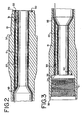
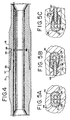
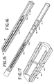
- Figures 6 through 10 are enlarged cross sectional views of Figure 6 from right to left, with Figure 7 showing an enlarged view of the right end of Figure 6, Figures 8 and 9 showing enlarged views of the center, and Figure 10 showing an enlarged view of the left side of Figure 6.
- the conductive tube is held in place in each end by means of an expansion plug 61 and a retaining plug 63, as shown in Figures 6 and 8.
- the expansion plug 61 preferably increases in diameter from front 62 to back 64, such that the diameter of the back 64 is larger than the initial inner diameter of the conductive tube 71.
- the expansion plug 61 has a center opening through which the wire 41 passes and is preferably made of metal, more preferably tool steel, most preferably Viscount 44 steel. Thus, as the expansion plug 61 is inserted in the conductive tube 71, the diameter of the conductive tube 71 is increased.
- the expansion plug 61 is inserted up to a distance relatively near the transition point 97, where the diameter of the passage 31 or 33 undergoes a change in diameter.
- the result of this insertion of the expansion plug 61 is that the diameter of the conductive tube 71 is larger on each end, so that the conductive tube 71 is held in place in the passages 31 and 33.
- the expansion plug 61 is held in place by a retaining plug 63, as shown in Figure 8.
- the retaining plug 63 is placed in the conductive tube 71 after the expansion plug 61 and has a center opening through which the wire 41 passes.
- the retaining plug 63 is made metal, more preferably tool steel, most preferably Viscount 44 steel.
- the retaining plug 61 has ridges along its outer diameter to dig into the inner diameter of the conductive tube 71 and hold the expansion plug 61 in place.
- the conductive tube 71 After exiting the holes 93 and 94, the conductive tube 71 passes through the interior of the body of the pipe section.
- the conductive tube may be insulated from the pipe in order to prevent possible galvanic corrosion.
- the preferred material with which to insulate the conductive tube 71 is PEEK ® .
- the coaxial cable 51 runs inside the conductive tube 71.
- the coaxial cable 51 has a conductive core 79 surrounded by a dielectric sheath 81.
- the coaxial cable 71 also has a conductive sheath surrounding the dielectric sheath 81 and in electrical contact with the conductive tube 71.
- the coaxial dielectric sheath 71 prevents electrical contact between the coaxial core 79 and the conductive tube 71.
- an inner layer of the dielectric sheath 81 is removed from around the conductive core 79 at each end, while leaving the outer layer of the dielectric sheath 81 in place next to the conductive tube 71. This allows insertion of the connector 53 around the conductive core 79 and within the dielectric sheath 81.
- the coaxial cable preferably has a characteristic impedance in the range of about 30 to about 120 ohms, most preferably with a characteristic impedance in the range of 50 to 75 ohms. Because the attenuation of coaxial cable decreases with increasing diameter, the largest diameter compatible with installation in pipe chosen for a particular application should be used. Most preferably the cable has a diameter of about 6.35mm (0.25") or larger.
- the shield should provide close to 100% coverage, and the core insulation should be made of a fully-dense polymer having low dielectric loss, most preferably from the family of polytetrafluoroethylene (PTFE) resins, Dupont's Teflon ® being one example. A foamed polymer may also be used as the core insulation.
- PTFE polytetrafluoroethylene
- the ratio of the impedance of the electrical conductor to the impedance of the first and second electrically conductive coils is between about 1:2 and 2:1. Most preferably, it is close to 1:1.
- the preferred data transmission system provides a relatively broad bandwidth. While not wishing to be bound by any particular theory, it is currently believed that this is accomplished by the low number of turns of the conductor and the low reluctance of the magnetic path, thus producing a surprisingly low mutual inductance for such a large diameter coil.
- the mutual inductance of the assembled toroid is about 1 micro Henry.
- peak signal transmission is at about 4 MHz, and at power transmission extends from about 1 MHz to about 12 MHz.
- the inductive reactance is about 65 ohms, and the attenuation is only about .35 dB per joint, equivalent to power transmission of about 92 percent.
- the communication element is thought to perform as a transmission-line transformer, wherein the coupling between the adjacent coils comprises distributed elements of both capacitance and inductance.
- the term "inductive coil” is intended to include both coils that transfer signals via induction as well as those coils that act as a transmission-line transformer.
- a serial filter is created, which has the effect of reducing the bandwidth. If each individual transformer had a narrow bandwidth, the band-pass of the filter would change as additional segments are added, which would require that each individual element be separately tuned according to its position in the system.
- a surprising feature of the invention is that identical segments can be assembled in any arbitrary number of joints while still enabling efficient signal coupling.
- a connector 53 in both the pin connector channel 31 and the box connector channel 33 is a connector 53.
- the connector 53 permits the coaxial cable 51 to transmit an electrical signal to the communication element 91.
- the connector 53 has a conductive sleeve 75 which fits around the conductive core 79.
- the connector 53 has an insulative coating 77 to prevent electrical contact between the conductive sleeve 75 and the conductive tube 71.
- the insulative coating is TEFLON ® .
- the connector 53 is pushed over the conductive core 79, making electrical contact with it.
- the connector 53 makes spring contact with the conductive core 79.
- connector 53 fits around a wire 41, which is in electrical contact with the communication element 91.
- the wire 41 is one end of the conductive coil 87.
- the wire 41 is preferably made of copper or silver-plated, copper-clad steel.
- the wire 41 has an insulative coating 59, which is made of varnish, enamel, or a polymer.
- the insulative coating 59 is a tough, flexible polymer such as high density polyethylene or polymerized tetrafluoroethane (PTFE).
- PTFE polymerized tetrafluoroethane
- the insulative coating 59 of the wire 41 is removed on the end of the wire 41 closest to the connector 53, in order to facilitate electrical contact between the conductive sleeve 75 and the wire 41.
- the connector 53 is crimped around the wire 41 in order to ensure good electrical contact between the conductive sleeve 75 and the wire 41.
- a centering insulator 73 is used to help position the connector 53.
- the centering insulator 73 is funnel-shaped at each end and is made of a dielectric material, preferably PTFE, most preferably PEEK ® .
- the centering insulator 73 is hollow in the center, allowing it to slide around the connector 53 and guide the connector 53 towards the core 79.
- a water-tight seal 55 is present in both the pin end connector channel 31 and the box end connector channel 33 to protect the connections from the high temperature and high pressure downhole conditions.
- a spacer 65 is placed between the retaining plug 63 and the water-tight seal.
- the spacer 65 is made of fiberglass.
- the seal 55 is located proximate to the retaining plug, as shown in Figure 8, and forms a seal between the inner surface of the conductive tube 71 and the outer surface of the wire 41.
- the seal comprises at least one O-ring 67 and at least one backup 69.
- the O-rings 67 are preferably made of rubber, more preferably fluoroelastomer, most preferably a fluoroelastomer marketed under the trademark AFLAS ® or VITON ® .
- the backups 69 are preferably made of PEEK ® and have a v-shaped indentation around one end. As an O-ring 67 is compressed, it moves into the indentation in the backup 69 and causes the outer diameter of the backup 69 to press against the conductive tube 71 and the inner diameter to press against the wire 41, thus helping to maintain the water-tight seal.
- a water-tight seal is present between the connector 53 and the inner surface of the conductive tube 71.
- the seal is provided by at least one circumferential groove on the outside of the connector and at least one gasket fitting therein.
- Alternate embodiments may protect the connection with a water tight seal in other locations, such as between the coaxial core 79 and the conductive tube 71, between the connector 53 and the conductive tube 71, and between the wire 41 and the connecting channels 31 and 33.
- Many types of data sources are important to management of a drilling operation. These include parameters such as hole temperature and pressure, salinity and pH of the drilling mud, magnetic declination and horizontal declination of the bottom-hole assembly, seismic look-ahead information about the surrounding formation, electrical resistivity of the formation, pore pressure of the formation, gamma ray characterization of the formation, and so forth.
- the high data rate provided by the present invention provides the opportunity for better use of this type of data and for the development of gathering and use of other types of data not presently available.
- the system will transmit data at a rate of at least 100 bits/second, more preferably, at least 20,000 bits/second, and most preferably, at least about 2,000,000 bits/second.
- the system preferably transmits data through at least 30 components powered only by the varying current supplied to one of the first conductive coils in one of the components. More preferably, the system transmits data through at least 50 components powered only by the varying current supplied to one of the first conductive coils in one of the components.
- the varying current supplied to the first conductive coil in the one component is driving a varying potential having a peak to peak value of between about 10 mV and about 20 V.
- the power loss between two connected components is less than about 5 percent.
- the transmission line of the invention will typically transmit the information signal a distance of 0.3 to 0.6km (1,000 to 2,000) feet before the signal is attenuated to the point where it will require amplification. This distance can be increased by sending a stronger signal, with attendant increased power consumption. However, many wells are drilled to depths of up to 6 to 9km (20,000 to 30,000) feet, which would necessitate use of repeaters to refurbish the signal.
- the amplifying units are provided in no more than 10 percent of the components in the string of downhole components, more preferably, no more than 3 percent.
- Such repeaters can be simple "dumb” repeaters that only increase the amplitude of the signal without any other modification.
- a simple amplifier will also amplify any noise in the signal.
- a digital repeater will provide a fresh signal without amplifying background noise.
- a "smart" repeater that detects any errors in the data stream and restores the signal, error free, while eliminating baseline noise, is preferred. Any of a number of known digital error correction schemes can be employed in a down-hole network incorporating a "smart" repeater.
- the repeater not only serves to regenerate the data stream, but also serves as a data source itself.
- information was available during drilling only from the bottom-hole assembly, as mud pulse data rates did not allow any intermediate nodes.
- information is available from any node along the drill string, thereby enabling distributed access to information from top to bottom. For instance, instead of relying on a single bottom hole pressure measurement, a pressure profile can now be generated along the entire drill string. This could be vital in underbalanced drilling, where to speed up drilling the pressure provided by the mud is less than that of the pore pressure in the surrounding formation. Any sudden pressure pulse or "kick" could be much more rapidly anticipated.
- inclinometers thermocouples
- gamma ray detectors gamma ray detectors
- acoustic wave detectors neutron sensors
- pressure transducers potentiometers
- strain gages seismic sources, and seismic receivers.
Landscapes
- Engineering & Computer Science (AREA)
- Mining & Mineral Resources (AREA)
- Geology (AREA)
- Life Sciences & Earth Sciences (AREA)
- Physics & Mathematics (AREA)
- Mechanical Engineering (AREA)
- Geochemistry & Mineralogy (AREA)
- Fluid Mechanics (AREA)
- Environmental & Geological Engineering (AREA)
- General Engineering & Computer Science (AREA)
- General Life Sciences & Earth Sciences (AREA)
- Power Engineering (AREA)
- Remote Sensing (AREA)
- Electromagnetism (AREA)
- Geophysics (AREA)
- Coupling Device And Connection With Printed Circuit (AREA)
- Earth Drilling (AREA)
- Drilling Tools (AREA)
- Computer And Data Communications (AREA)
Claims (55)
- System zum Übertragen von Daten durch einen Strang von Tiefbohrelementen, welches mehrere Tiefbohrelemente umfasst, jedes mit einem Stiftende (13) und einem Gehäuse-Ende (11), wobei das Stiftende (13) eines Tiefbohrelements dafür geeignet ist, mit dem Gehäuse-Ende (11) eines anderen Tiefbohrelements verbunden zu werden, wobei jedes Stiftende (13) Außengewinde (19) und distal zu den Außengewinden eine innere Stift-Stirnseite (35) aufweist, wobei die innere Stift-Stirnseite (35) im Allgemeinen quer zu der Längsachse des Tiefbohrelements angeordnet ist, und wobei jedes Gehäuse-Ende (11) eine innere Schulter-Stirnseite (36) mit Innengewinden (21) distal zu der Schulter-Stirnseite (36) aufweist, wobei die innere Schulter-Stirnseite (36) im Allgemeinen quer zu der Längsachse des Tiefbohrelements angeordnet ist, und wobei die innere Stift-Stirnseite (35) und die innere Schulter-Stirnseite (36) aneinander ausgerichtet sind und nah beieinander liegen, wenn das Stiftende des einen Elements in ein Gehäuse-Ende des anderen Elements geschraubt wird; ein erstes Kommunikationselement (90), welches sich innerhalb einer ersten Ausnehmung (32) befindet, die in jeder inneren Stift-Stirnseite (35) ausgebildet ist, ein zweites Kommunikationselement (92), welches sich innerhalb einer zweiten Ausnehmung (34) befindet, die in jeder inneren Schulter-Stirnseite (36) ausgebildet ist, und einen Leiter, welcher mit jedem ersten und zweiten Kommunikationselement (90, 92) in jedem Element in Verbindung steht und zwischen diesen verläuft; dadurch gekennzeichnet, dass:das erste und zweite Kommunikationselement (90, 92) jeweils einen ersten Kontakt und einen zweiten Kontakt aufweist;der Leiter zwischen dem ersten und zweiten Kommunikationselement ein Koaxialkabel umfasst, wobei das Koaxialkabel (51) eine leitfähige Röhre (71) und innerhalb dieser einen leitfähigen Kern (79) aufweist;ein erster bzw. zweiter Steckverbinder (53) das erste bzw. zweite Kommunikationselement (90, 92) mit dem Koaxialkabel (51) verbindet, wobei jeder Steckverbinder (53) eine leitfähige Buchse (75) aufweist, welche konzentrisch innerhalb der leitfähigen Röhre liegt und um den leitfähigen Kern (79) herum angepasst ist und mit diesem in elektrischem Kontakt steht, wobei die leitfähige Buchse (75) von der leitfähigen Röhre (71) elektrisch isoliert ist;wobei die leitfähige Buchse (75) jedes Steckverbinders (53) in elektrischem Kontakt mit dem ersten Kontakt des entsprechenden ersten oder zweiten Kommunikationselements (90, 92) steht, wobei die leitfähige Röhre (71) in elektrischem Kontakt mit dem zweiten Kontakt sowohl des ersten als auch des zweiten Kommunikationselements (90, 92) steht.
- System nach Anspruch 1, wobei es sich bei dem ersten und zweiten Kommunikationselement (90, 92) um Induktionsspulen handelt.
- System nach Anspruch 2, wobei die Induktionsspulen mindestens eine Drahtschlaufe aufweisen, welche in eine kreisförmige Wanne aus einem magnetisch leitenden, elektrisch isolierenden Material eingesetzt ist, wobei der Draht ein erstes Ende und ein zweites Ende aufweist, wobei das erste Ende der erste Kontakt ist und das zweite Ende der zweite Kontakt ist.
- System nach Anspruch 1, wobei jeder Bohrgestängeabschnitt einen Teil mit einer verstärkten Wanddicke sowohl am ersten als auch am zweiten Ende aufweist, woraus sich ein kleinerer Durchmesser der zentralen Bohrung am ersten und zweiten Ende ergibt, und
wobei der erste und zweite Durchgang durch die Teile mit verstärkter Wanddicke und im Allgemeinen parallel zur Längsachse des Bohrgestänges verläuft. - System nach Anspruch 4, wobei der erste und zweite Durchgang jeweils einen Teil mit größerem Durchmesser und einen Teil mit kleinerem Durchmesser aufweist,
wobei der Teil mit größerem Durchmesser näher an der ersten bzw. zweiten Ausnehmung liegt und der Teil mit kleinerem Durchmesser näher am Ende des Durchgangs liegt, welcher in die zentrale Bohrung einmündet, und wobei sich der erste bzw. zweite Steckverbinder innerhalb des Teils mit größerem Durchmesser des ersten bzw. zweiten Durchgangs befindet. - System nach Anspruch 5, wobei die leitfähige Röhre (71) zumindest über die Länge des Koaxialkabels (51) verläuft, und wobei die leitfähige Röhre (71) einen Außendurchmesser entlang dem größten Teil ihrer Länge aufweist, welcher in die Teile mit kleinerem Durchmesser des ersten und zweiten Durchgangs passt, und einen vergrößerten Außendurchmesser an beiden Enden, welcher in die Teile mit größerem Durchmesser des ersten und zweiten Durchgangs passt, wobei aber der vergrößerte Außendurchmesser nicht in die Teile mit kleinerem Durchmesser passt, wodurch das Koaxialkabel innerhalb des Bohrgestängeabschnitts in Position gehalten wird.
- System nach Anspruch 6, welches ferner einen ersten und zweiten Dehnungsstopfen umfasst, von denen jeder einen zentralen Durchgang aufweist und jeder derart in die leitfähige Röhre eingepresst ist, dass der vergrößerte Außendurchmesser der leitfähigen Röhre innerhalb der Teile mit größerem Durchmesser des ersten bzw. zweiten Durchgangs gehalten wird.
- System nach Anspruch 1, wobei die leitfähige Röhre (71) über die Länge des Koaxialkabels (51) verläuft.
- System nach Anspruch 8, wobei die leitfähige Röhre (71) aus einem starken Metall hergestellt ist.
- System nach Anspruch 9, wobei das Metall Stahl ist.
- System nach Anspruch 10, wobei die leitfähige Röhre (71) relativ zu dem Tiefbohrelement unter Spannung gehalten wird.
- System nach Anspruch 1, wobei es sich bei dem ersten und zweiten Kommunikationselement um Induktionsspulen handelt und die Induktionsspulen aus einer einzelnen Drahtschlaufe gebildet sind.
- System nach Anspruch 3, wobei die Wanne aus Segmenten eines magnetisch leitenden, elektrisch isolierenden Materials gebildet ist.
- System nach Anspruch 13, wobei die Wanne Ferrit umfasst.
- System nach Anspruch 13, wobei die Segmente in einer Nut gehalten werden, die in einem Metallring ausgebildet ist.
- System nach Anspruch 15, wobei die Segmente und der Draht von einem isolierenden Material umhüllt sind.
- System nach Anspruch 16, wobei das isolierende Material ausgewählt ist aus der Gruppe, bestehend aus Polyurethan, Polytetrafluorethylen, Perfluoralkoxy und Epoxid.
- System nach Anspruch 15, wobei der Metallring eine Öffnung aufweist, durch welche zumindest das erste Ende des Drahts hindurchführt.
- System nach Anspruch 18, wobei das zweite Ende des Drahts, der Metallring und die leitfähige Röhre in elektrischem Kontakt miteinander stehen und das erste Ende des Drahts in elektrischem Kontakt mit der leitfähigen Buchse steht.
- System nach Anspruch 19, welches ferner eine Haltebrücke umfasst, durch welche das erste Ende des Drahts verläuft, und welche das erste Ende des Drahts vom Metallring isoliert.
- System nach Anspruch 1, wobei es sich bei den Elementen um Bohrgestängeabschnitte handelt, welche jeweils eine durch sie führende zentrale Bohrung aufweisen, und wobei das erste bzw. zweite Kommunikationselement innerhalb einer ersten bzw. zweiten Ausnehmung am ersten bzw. zweiten Ende des Bohrgestänges angeordnet sind, und welches ferner einen ersten Durchgang umfasst, der zwischen der ersten Ausnehmung und der zentralen Bohrung hindurchführt, und einen zweiten Durchgang, der zwischen der ersten Ausnehmung und der zentralen Bohrung hindurchführt, und wobei der erste bzw. zweite Steckverbinder im ersten bzw. zweiten Durchgang angeordnet sind.
- System nach Anspruch 21, wobei jeder Bohrgestängeabschnitt einen Teil mit einer verstärkten Wanddicke sowohl am ersten als auch am zweiten Ende aufweist, woraus sich ein kleinerer Durchmesser der zentralen Bohrung am ersten und zweiten Ende ergibt, und
wobei der erste und zweite Durchgang durch die Teile mit verstärkter Wanddicke und im Allgemeinen parallel zur Längsachse des Bohrgestänges verläuft. - System nach Anspruch 22, wobei der erste und zweite Durchgang jeweils einen Teil mit größerem Durchmesser und einen Teil mit kleinerem Durchmesser aufweist,
wobei der Teil mit größerem Durchmesser näher an der ersten bzw. zweiten Ausnehmung liegt und der Teil mit kleinerem Durchmesser näher am Ende des Durchgangs liegt, welcher in die zentrale Bohrung einmündet, und wobei sich der erste bzw. zweite Steckverbinder innerhalb des Teils mit größerem Durchmesser des ersten bzw. zweiten Durchgangs befindet. - System nach Anspruch 22, wobei die leitfähige Röhre zumindest über die Länge des Koaxialkabels verläuft, und wobei die leitfähige Röhre einen Außendurchmesser entlang dem größten Teil ihrer Länge aufweist, welcher in die Teile mit kleinerem Durchmesser des ersten und zweiten Durchgangs passt, und einen vergrößerten Außendurchmesser an beiden Enden, welcher in die Teile mit größerem Durchmesser des ersten und zweiten Durchgangs passt, wobei aber der vergrößerte Außendurchmesser nicht in die Teile mit kleinerem Durchmesser passt, wodurch das Koaxialkabel innerhalb des Bohrgestängeabschnitts in Position gehalten wird.
- System nach Anspruch 24, welches ferner einen ersten und zweiten Dehnungsstopfen umfasst, von denen jeder einen zentralen Durchgang aufweist und jeder derart in die leitfähige Röhre eingepresst ist, dass der vergrößerte Außendurchmesser der leitfähigen Röhre innerhalb der Teile mit größerem Durchmesser des ersten bzw. zweiten Durchgangs gehalten wird.
- System nach Anspruch 25, welches ferner einen ersten und zweiten Haltestopfen benachbart zu dem entsprechenden ersten und zweiten Dehnungsstopfen umfasst, wobei jeder der Haltestopfen Rippen auf seiner Außenfläche aufweist, um die Dehnungsstopfen in Position zu halten.
- System nach Anspruch 26, wobei die Dehnungsstopfen und die Haltestopfen aus Stahl hergestellt sind.
- System nach Anspruch 1, wobei das Koaxialkabel ferner ein dielektrisches Material zwischen der leitfähigen Röhre und dem leitfähigen Kern aufweist, welches über den größten Teil der Länge des Kabels verläuft, aber an beiden Enden des Kabels nicht vorhanden ist, um dadurch die Verbindung zu dem ersten und zweiten Steckverbinder zu erleichtern.
- System nach Anspruch 28, wobei das Koaxialkabel ferner einen leitfähigen Mantel außerhalb des dielektrischen Materials und innerhalb der leitfähigen Röhre aufweist, und wobei der leitfähige Mantel über den größten Teil der Länge des Kabels verläuft, aber an beiden Enden des Kabels nicht vorhanden ist, um dadurch die Verbindung zu dem ersten und zweiten Steckverbinder zu erleichtern.
- System nach Anspruch 1, wobei jeder Steckverbinder ferner eine Führung für die leitfähige Buchse aufweist, wobei die Führung aus einem dielektrischen Material hergestellt ist und einen Führungsdurchgang aufweist, durch welchen die leitfähige Buchse verläuft, wobei der Führungsdurchgang an einem oder beiden Enden trichterförmig ist.
- System nach Anspruch 1, welches ferner eine wasserdichte Versiegelung zwischen der Außenfläche der leitfähigen Buchse und der Innenfläche der leitfähigen Röhre umfasst.
- System nach Anspruch 31, wobei die Versiegelung dafür geeignet ist, Drücken von mindestens 172 MPa (25.000 Pfund je Quadratinch) und Temperaturen von mindestens 200 Grad Celsius standzuhalten.
- System nach Anspruch 31, wobei die Versiegelung durch mindestens einen O-Ring bereitgestellt wird.
- System nach Anspruch 1, wobei das erste und zweite Kommunikationselement jeweils eine Induktionsspule aufweist, welche mindestens eine Drahtschlaufe aufweist,
wobei in jedem Kommunikationselement der erste Kontakt ein erstes Ende des Drahts umfasst und der zweite Kontakt ein zweites Ende des Drahts umfasst, und wobei der erste und zweite Steckverbinder jeweils ferner eine wasserdichte Versiegelung zwischen dem zweiten Ende des Drahts und der Innenseite der leitfähigen Röhre aufweist. - System nach Anspruch 34, wobei die wasserdichte Versiegelung mindestens eine Dichtung umfasst, durch welche das erste Ende des Drahts verläuft, und welche eine Versiegelung mit der Innenfläche der leitfähigen Röhre bildet.
- System nach Anspruch 35, wobei die Versiegelung dafür geeignet ist, Drücken von mindestens 138 MPa (20.000 Pfund je Quadratinch) und Temperaturen von mindestens 200 Grad Celsius standzuhalten.
- System nach Anspruch 35, wobei die Dichtung aus einem Material hergestellt ist, ausgewählt aus der Gruppe, bestehend aus Pyrophyllit, Kautschuk-Glasfaser und Fluorelastomer.
- System nach Anspruch 37, wobei die Dichtung einen O-Ring umfasst.
- System nach Anspruch 38, wobei jeder O-Ring einem Verschlussring benachbart ist, wobei der Verschlussring gewöhnlich den O-Ring unter Tiefbohrbedingungen in Position hält.
- System nach Anspruch 34, wobei der erste und zweite Steckverbinder ferner eine zweite wasserdichte Versiegelung zwischen der Außenfläche der leitfähigen Buchse und der Innenfläche der leitfähigen Röhre aufweisen.
- Verfahren zum elektrischen Verbinden von Kommunikationselementen an gegenüberliegenden Enden eines Tiefbohrelements durch einen Koaxialleiter, wobei das Verfahren das Folgende umfasst:Bereitstellen eines Koaxialkabels als Leiter zwischen dem ersten und zweiten Kommunikationselement, wobei das Koaxialkabel eine leitfähige Röhre, einen leitfähigen Kern innerhalb dieser und ein dielektrisches Material zwischen der leitfähigen Röhre und dem leitfähigen Kern aufweist;Bereitstellen eines ersten und zweiten Steckverbinders zum Verbinden des entsprechenden ersten und zweiten Kommunikationselements mit dem Koaxialkabel, wobei der erste und zweite Steckverbinder jeweils eine leitfähige Buchse aufweist, welche um den leitfähigen Kern herum angepasst ist und in elektrischem Kontakt zu diesem steht, wobei die leitfähige Buchse von dem leitfähigen Mantel elektrisch isoliert ist;Entfernen eines Teils des dielektrischen Materials an beiden Enden des Koaxialkabels, um dadurch einen lichten Raum für die leitfähige Buchse bereitzustellen; undSchieben des ersten und zweiten Steckverbinders über beide Enden des Koaxialkabels.
- Verfahren nach Anspruch 41, wobei das Koaxialkabel ferner einen leitfähigen Mantel in elektrischem Kontakt mit der leitfähigen Röhre aufweist, und wobei an beiden Enden ein Teil des leitfähigen Mantels entfernt wird, um dadurch einen lichten Raum für die erste Buchse zu schaffen.
- Verfahren nach Anspruch 41, wobei die leitfähige Röhre mindestens über die gesamte Länge des Koaxialkabels verläuft.
- Verfahren nach Anspruch 41, wobei es sich bei den Elementen um Bohrgestängeabschnitte handelt, welche jeweils eine durch sie führende zentrale Bohrung aufweisen, und wobei das erste bzw. zweite Kommunikationselement innerhalb einer ersten bzw. zweiten Ausnehmung am ersten bzw. zweiten Ende des Bohrgestänges angeordnet sind, und welches ferner einen ersten Durchgang umfasst, der zwischen der ersten Ausnehmung und der zentralen Bohrung hindurchführt, und einen zweiten Durchgang, der zwischen der ersten Ausnehmung und der zentralen Bohrung hindurchführt, und wobei der erste bzw. zweite Steckverbinder im ersten bzw. zweiten Durchgang angeordnet sind.
- Verfahren nach Anspruch 44, wobei jeder Bohrgestängeabschnitt einen Teil mit einer verstärkten Wanddicke an beiden Enden aufweist, woraus sich ein kleinerer Durchmesser der zentralen Bohrung an beiden Enden ergibt, und wobei der erste und zweite Durchgang durch die Teile mit verstärkter Wanddicke und im Allgemeinen parallel zur Längsachse des Bohrgestänges verläuft.
- Verfahren nach Anspruch 45, wobei der erste und zweite Durchgang jeweils einen Teil mit größerem Durchmesser und einen Teil mit kleinerem Durchmesser aufweist, wobei der Teil mit größerem Durchmesser näher an der ersten bzw. zweiten Ausnehmung liegt und der Teil mit kleinerem Durchmesser näher am Ende des Durchgangs liegt, welcher in die zentrale Bohrung einmündet, und wobei der erste bzw. zweite Steckverbinder innerhalb des Teils mit größerem Durchmesser des ersten bzw. zweiten Durchgangs eingefügt ist.
- Verfahren nach Anspruch 46, wobei die leitfähige Röhre zumindest über die Länge des Koaxialkabels verläuft, und wobei die leitfähige Röhre einen Außendurchmesser entlang dem größten Teil ihrer Länge aufweist, welcher in die Teile mit kleinerem Durchmesser des ersten und zweiten Durchgangs passt, und wobei der Außendurchmesser der leitfähigen Röhre an beiden Enden nach dem Einfügen in die Teile mit größerem Durchmesser des ersten und zweiten Durchgangs erweitert wird, um dadurch das Koaxialkabel innerhalb des Bohrgestängeabschnitts in Position zu halten.
- Verfahren nach Anspruch 47, wobei die leitfähige Röhre relativ zum Bohrgestänge unter Spannung gehalten wird.
- Verfahren nach Anspruch 47, wobei der Außendurchmesser der leitfähigen Röhre erweitert wird, indem in jedes Ende ein Dehnungsstopfen eingefügt wird.
- Verfahren nach Anspruch 49, wobei jeder Dehnungsstopfen einen Durchgang aufweist, durch welchen ein Draht in elektrischem Kontakt mit dem leitfähigen Kern verläuft.
- Verfahren nach Anspruch 50, wobei jeder Dehnungsstopfen durch einen Haltestopfen mit Rippen auf seiner Außenfläche in Position gehalten wird.
- Verfahren nach Anspruch 41, welches ferner eine Führung für die leitfähige Buchse umfasst, wobei die Führung aus einem dielektrischen Material hergestellt ist und einen Führungsdurchgang aufweist, durch welchen die leitfähige Buchse verläuft, wobei der Führungsdurchgang an einem oder beiden Enden trichterförmig ist.
- Verfahren nach Anspruch 41, welches ferner eine wasserdichte Versiegelung zwischen der Außenfläche der leitfähigen Buchse und der Innenfläche der leitfähigen Röhre umfasst.
- Verfahren nach Anspruch 41, wobei das erste und zweite Kommunikationselement jeweils eine Induktionsspule aufweist, welche mindestens eine Drahtschlaufe aufweist, wobei in jedem Kommunikationselement ein erstes Ende des Drahts in elektrischem Kontakt mit der leitfähigen Röhre steht und ein zweites Ende des Drahts in elektrischem Kontakt mit der leitfähigen Buchse steht.
- Verfahren nach Anspruch 54, wobei der erste und zweite Steckverbinder jeweils ferner eine wasserdichte Versiegelung zwischen dem zweiten Ende des Drahts und der Innenseite der leitfähigen Röhre aufweisen.
Applications Claiming Priority (3)
| Application Number | Priority Date | Filing Date | Title |
|---|---|---|---|
| US44410003P | 2003-01-31 | 2003-01-31 | |
| US444100P | 2003-01-31 | ||
| PCT/GB2004/000166 WO2004067901A1 (en) | 2003-01-31 | 2004-01-21 | Data transmission system for a downhole component |
Publications (2)
| Publication Number | Publication Date |
|---|---|
| EP1588018A1 EP1588018A1 (de) | 2005-10-26 |
| EP1588018B1 true EP1588018B1 (de) | 2007-07-11 |
Family
ID=32825398
Family Applications (1)
| Application Number | Title | Priority Date | Filing Date |
|---|---|---|---|
| EP04703847A Expired - Lifetime EP1588018B1 (de) | 2003-01-31 | 2004-01-21 | Datenübertragungssystem für ein tiefbohrelement |
Country Status (7)
| Country | Link |
|---|---|
| US (3) | US6844498B2 (de) |
| EP (1) | EP1588018B1 (de) |
| AT (1) | ATE366862T1 (de) |
| CA (1) | CA2512164C (de) |
| DE (1) | DE602004007482T2 (de) |
| MX (1) | MXPA05007490A (de) |
| WO (1) | WO2004067901A1 (de) |
Cited By (1)
| Publication number | Priority date | Publication date | Assignee | Title |
|---|---|---|---|---|
| WO2013006179A1 (en) * | 2011-07-07 | 2013-01-10 | Woodhead Industries, Inc. | Harsh duty receptacle connector |
Families Citing this family (166)
| Publication number | Priority date | Publication date | Assignee | Title |
|---|---|---|---|---|
| US6992554B2 (en) * | 2000-07-19 | 2006-01-31 | Intelliserv, Inc. | Data transmission element for downhole drilling components |
| US7040003B2 (en) * | 2000-07-19 | 2006-05-09 | Intelliserv, Inc. | Inductive coupler for downhole components and method for making same |
| US7253745B2 (en) * | 2000-07-19 | 2007-08-07 | Intelliserv, Inc. | Corrosion-resistant downhole transmission system |
| GB0115524D0 (en) * | 2001-06-26 | 2001-08-15 | Xl Technology Ltd | Conducting system |
| SE524538C2 (sv) * | 2002-02-19 | 2004-08-24 | Volvo Lastvagnar Ab | Anordning för styrning av utgående motormoment vid lastfordon utrustat med differentialspärrar |
| WO2004033847A1 (en) * | 2002-10-10 | 2004-04-22 | Varco I/P, Inc. | Apparatus and method for transmitting a signal in a wellbore |
| US7207396B2 (en) * | 2002-12-10 | 2007-04-24 | Intelliserv, Inc. | Method and apparatus of assessing down-hole drilling conditions |
| US7193527B2 (en) * | 2002-12-10 | 2007-03-20 | Intelliserv, Inc. | Swivel assembly |
| US6844498B2 (en) * | 2003-01-31 | 2005-01-18 | Novatek Engineering Inc. | Data transmission system for a downhole component |
| US7852232B2 (en) * | 2003-02-04 | 2010-12-14 | Intelliserv, Inc. | Downhole tool adapted for telemetry |
| US7053788B2 (en) * | 2003-06-03 | 2006-05-30 | Intelliserv, Inc. | Transducer for downhole drilling components |
| US7528736B2 (en) * | 2003-05-06 | 2009-05-05 | Intelliserv International Holding | Loaded transducer for downhole drilling components |
| US7193526B2 (en) * | 2003-07-02 | 2007-03-20 | Intelliserv, Inc. | Downhole tool |
| TWI251815B (en) | 2003-08-07 | 2006-03-21 | Benq Corp | Disk drive avoiding flying disk condition |
| US7139218B2 (en) * | 2003-08-13 | 2006-11-21 | Intelliserv, Inc. | Distributed downhole drilling network |
| US7019665B2 (en) * | 2003-09-02 | 2006-03-28 | Intelliserv, Inc. | Polished downhole transducer having improved signal coupling |
| US6968611B2 (en) * | 2003-11-05 | 2005-11-29 | Intelliserv, Inc. | Internal coaxial cable electrical connector for use in downhole tools |
| US7063134B2 (en) * | 2004-06-24 | 2006-06-20 | Tenneco Automotive Operating Company Inc. | Combined muffler/heat exchanger |
| US20060062249A1 (en) * | 2004-06-28 | 2006-03-23 | Hall David R | Apparatus and method for adjusting bandwidth allocation in downhole drilling networks |
| US7200070B2 (en) * | 2004-06-28 | 2007-04-03 | Intelliserv, Inc. | Downhole drilling network using burst modulation techniques |
| US7253671B2 (en) * | 2004-06-28 | 2007-08-07 | Intelliserv, Inc. | Apparatus and method for compensating for clock drift in downhole drilling components |
| US20050284659A1 (en) * | 2004-06-28 | 2005-12-29 | Hall David R | Closed-loop drilling system using a high-speed communications network |
| US7091810B2 (en) * | 2004-06-28 | 2006-08-15 | Intelliserv, Inc. | Element of an inductive coupler |
| US7248177B2 (en) * | 2004-06-28 | 2007-07-24 | Intelliserv, Inc. | Down hole transmission system |
| US7319410B2 (en) * | 2004-06-28 | 2008-01-15 | Intelliserv, Inc. | Downhole transmission system |
| US7198118B2 (en) * | 2004-06-28 | 2007-04-03 | Intelliserv, Inc. | Communication adapter for use with a drilling component |
| US7093654B2 (en) * | 2004-07-22 | 2006-08-22 | Intelliserv, Inc. | Downhole component with a pressure equalization passageway |
| US7201240B2 (en) * | 2004-07-27 | 2007-04-10 | Intelliserv, Inc. | Biased insert for installing data transmission components in downhole drilling pipe |
| US7274304B2 (en) * | 2004-07-27 | 2007-09-25 | Intelliserv, Inc. | System for loading executable code into volatile memory in a downhole tool |
| US20060033638A1 (en) * | 2004-08-10 | 2006-02-16 | Hall David R | Apparatus for Responding to an Anomalous Change in Downhole Pressure |
| US7165633B2 (en) * | 2004-09-28 | 2007-01-23 | Intelliserv, Inc. | Drilling fluid filter |
| US7303029B2 (en) * | 2004-09-28 | 2007-12-04 | Intelliserv, Inc. | Filter for a drill string |
| US7135933B2 (en) * | 2004-09-29 | 2006-11-14 | Intelliserv, Inc. | System for adjusting frequency of electrical output pulses derived from an oscillator |
| US7168510B2 (en) * | 2004-10-27 | 2007-01-30 | Schlumberger Technology Corporation | Electrical transmission apparatus through rotating tubular members |
| US8033328B2 (en) * | 2004-11-05 | 2011-10-11 | Schlumberger Technology Corporation | Downhole electric power generator |
| US7548068B2 (en) * | 2004-11-30 | 2009-06-16 | Intelliserv International Holding, Ltd. | System for testing properties of a network |
| FR2881172B1 (fr) * | 2005-01-25 | 2008-03-14 | Deviatec Sarl | Tige tubulaire de forage |
| US7298287B2 (en) * | 2005-02-04 | 2007-11-20 | Intelliserv, Inc. | Transmitting data through a downhole environment |
| US7132904B2 (en) * | 2005-02-17 | 2006-11-07 | Intelliserv, Inc. | Apparatus for reducing noise |
| US7413021B2 (en) * | 2005-03-31 | 2008-08-19 | Schlumberger Technology Corporation | Method and conduit for transmitting signals |
| US8344905B2 (en) | 2005-03-31 | 2013-01-01 | Intelliserv, Llc | Method and conduit for transmitting signals |
| US7304835B2 (en) | 2005-04-28 | 2007-12-04 | Datavan International Corp. | Mainframe and power supply arrangement |
| US20060256718A1 (en) * | 2005-05-16 | 2006-11-16 | Hall David R | Apparatus for Regulating Bandwidth |
| US7212040B2 (en) * | 2005-05-16 | 2007-05-01 | Intelliserv, Inc. | Stabilization of state-holding circuits at high temperatures |
| US20080012569A1 (en) * | 2005-05-21 | 2008-01-17 | Hall David R | Downhole Coils |
| US8264369B2 (en) * | 2005-05-21 | 2012-09-11 | Schlumberger Technology Corporation | Intelligent electrical power distribution system |
| US7277026B2 (en) * | 2005-05-21 | 2007-10-02 | Hall David R | Downhole component with multiple transmission elements |
| US7382273B2 (en) * | 2005-05-21 | 2008-06-03 | Hall David R | Wired tool string component |
| US7535377B2 (en) * | 2005-05-21 | 2009-05-19 | Hall David R | Wired tool string component |
| US20090151926A1 (en) * | 2005-05-21 | 2009-06-18 | Hall David R | Inductive Power Coupler |
| US7504963B2 (en) | 2005-05-21 | 2009-03-17 | Hall David R | System and method for providing electrical power downhole |
| US8004421B2 (en) * | 2006-05-10 | 2011-08-23 | Schlumberger Technology Corporation | Wellbore telemetry and noise cancellation systems and method for the same |
| US7268697B2 (en) * | 2005-07-20 | 2007-09-11 | Intelliserv, Inc. | Laterally translatable data transmission apparatus |
| US8826972B2 (en) * | 2005-07-28 | 2014-09-09 | Intelliserv, Llc | Platform for electrically coupling a component to a downhole transmission line |
| US20070023185A1 (en) * | 2005-07-28 | 2007-02-01 | Hall David R | Downhole Tool with Integrated Circuit |
| US7275594B2 (en) * | 2005-07-29 | 2007-10-02 | Intelliserv, Inc. | Stab guide |
| JP2009503306A (ja) * | 2005-08-04 | 2009-01-29 | シュルンベルジェ ホールディングス リミテッド | 坑井遠隔計測システム用インターフェイス及びインターフェイス方法 |
| US7299867B2 (en) * | 2005-09-12 | 2007-11-27 | Intelliserv, Inc. | Hanger mounted in the bore of a tubular component |
| US9109439B2 (en) * | 2005-09-16 | 2015-08-18 | Intelliserv, Llc | Wellbore telemetry system and method |
| US20070063865A1 (en) * | 2005-09-16 | 2007-03-22 | Schlumberger Technology Corporation | Wellbore telemetry system and method |
| US8297375B2 (en) | 2005-11-21 | 2012-10-30 | Schlumberger Technology Corporation | Downhole turbine |
| US7571780B2 (en) * | 2006-03-24 | 2009-08-11 | Hall David R | Jack element for a drill bit |
| US8522897B2 (en) | 2005-11-21 | 2013-09-03 | Schlumberger Technology Corporation | Lead the bit rotary steerable tool |
| US8408336B2 (en) | 2005-11-21 | 2013-04-02 | Schlumberger Technology Corporation | Flow guide actuation |
| US8360174B2 (en) * | 2006-03-23 | 2013-01-29 | Schlumberger Technology Corporation | Lead the bit rotary steerable tool |
| US7298286B2 (en) * | 2006-02-06 | 2007-11-20 | Hall David R | Apparatus for interfacing with a transmission path |
| US7350565B2 (en) * | 2006-02-08 | 2008-04-01 | Hall David R | Self-expandable cylinder in a downhole tool |
| GB0607551D0 (en) * | 2006-04-18 | 2006-05-24 | Read Well Services Ltd | Apparatus and method |
| US7598886B2 (en) * | 2006-04-21 | 2009-10-06 | Hall David R | System and method for wirelessly communicating with a downhole drill string |
| US20070278009A1 (en) * | 2006-06-06 | 2007-12-06 | Maximo Hernandez | Method and Apparatus for Sensing Downhole Characteristics |
| US7572134B2 (en) * | 2006-07-03 | 2009-08-11 | Hall David R | Centering assembly for an electric downhole connection |
| US7649475B2 (en) * | 2007-01-09 | 2010-01-19 | Hall David R | Tool string direct electrical connection |
| US7404725B2 (en) * | 2006-07-03 | 2008-07-29 | Hall David R | Wiper for tool string direct electrical connection |
| US7488194B2 (en) * | 2006-07-03 | 2009-02-10 | Hall David R | Downhole data and/or power transmission system |
| US7656309B2 (en) * | 2006-07-06 | 2010-02-02 | Hall David R | System and method for sharing information between downhole drill strings |
| US7527105B2 (en) * | 2006-11-14 | 2009-05-05 | Hall David R | Power and/or data connection in a downhole component |
| US7617877B2 (en) * | 2007-02-27 | 2009-11-17 | Hall David R | Method of manufacturing downhole tool string components |
| US7934570B2 (en) * | 2007-06-12 | 2011-05-03 | Schlumberger Technology Corporation | Data and/or PowerSwivel |
| US8102276B2 (en) * | 2007-08-31 | 2012-01-24 | Pathfinder Energy Sevices, Inc. | Non-contact capacitive datalink for a downhole assembly |
| BRPI0819298B1 (pt) | 2007-11-20 | 2019-03-12 | National Oilwell Varco, L.P. | Ferramenta de furo abaixo, sistema e método para circular fluido dentro de um furo de poço |
| US7537051B1 (en) | 2008-01-29 | 2009-05-26 | Hall David R | Downhole power generation assembly |
| US7694558B2 (en) * | 2008-02-11 | 2010-04-13 | Baker Hughes Incorporated | Downhole washout detection system and method |
| US20090207041A1 (en) * | 2008-02-19 | 2009-08-20 | Baker Hughes Incorporated | Downhole measurement while drilling system and method |
| US8600679B2 (en) * | 2008-02-27 | 2013-12-03 | Baker Hughes Incorporated | System and method to locate, monitor and quantify friction between a drillstring and a wellbore |
| AU2009222010B2 (en) * | 2008-03-03 | 2015-06-25 | Intelliserv International Holding, Ltd | Monitoring downhole conditions with drill string distributed measurement system |
| WO2009133474A2 (en) * | 2008-04-08 | 2009-11-05 | Schlumberger Canada Limited | Wired drill pipe cable connector system |
| US8237584B2 (en) * | 2008-04-24 | 2012-08-07 | Schlumberger Technology Corporation | Changing communication priorities for downhole LWD/MWD applications |
| US8061443B2 (en) * | 2008-04-24 | 2011-11-22 | Schlumberger Technology Corporation | Downhole sample rate system |
| US8242928B2 (en) | 2008-05-23 | 2012-08-14 | Martin Scientific Llc | Reliable downhole data transmission system |
| GB0814207D0 (en) * | 2008-08-04 | 2008-09-10 | Pedem Ltd | Connection apparatus and method |
| US8164980B2 (en) * | 2008-10-20 | 2012-04-24 | Baker Hughes Incorporated | Methods and apparatuses for data collection and communication in drill string components |
| US8009510B2 (en) | 2008-10-23 | 2011-08-30 | Schlumberger Technology Corporation | Two way check shot and reverse VSP while drilling |
| US8109329B2 (en) * | 2009-01-15 | 2012-02-07 | Intelliserv, L.L.C. | Split-coil, redundant annular coupler for wired downhole telemetry |
| US7980331B2 (en) * | 2009-01-23 | 2011-07-19 | Schlumberger Technology Corporation | Accessible downhole power assembly |
| US20100193186A1 (en) * | 2009-02-03 | 2010-08-05 | Smith David R | Method and apparatus to construct and log a well |
| US8049506B2 (en) | 2009-02-26 | 2011-11-01 | Aquatic Company | Wired pipe with wireless joint transceiver |
| US20100224356A1 (en) * | 2009-03-06 | 2010-09-09 | Smith International, Inc. | Apparatus for electrical power and/or data transfer between rotating components in a drill string |
| US8028768B2 (en) * | 2009-03-17 | 2011-10-04 | Schlumberger Technology Corporation | Displaceable plug in a tool string filter |
| EP2236736B8 (de) * | 2009-03-30 | 2018-02-14 | Vallourec Drilling Products France | Verdrahtetes Bohrungsrohr |
| AT508272B1 (de) * | 2009-06-08 | 2011-01-15 | Advanced Drilling Solutions Gmbh | Vorrichtung zum verbinden von elektrischen leitungen |
| US8665109B2 (en) | 2009-09-09 | 2014-03-04 | Intelliserv, Llc | Wired drill pipe connection for single shouldered application and BHA elements |
| JP5421064B2 (ja) * | 2009-10-26 | 2014-02-19 | 後藤電子 株式会社 | 高周波高圧高電流電線 |
| IT1400540B1 (it) * | 2010-05-28 | 2013-06-11 | Pe Gas Us S R L | Connettore elettrico, in particolare per una batteria di trivellazione. |
| EP2415961A1 (de) * | 2010-08-03 | 2012-02-08 | Vetco Gray Controls Limited | Stromversorgung für Unterwasservorrichtungen |
| FR2965415B1 (fr) * | 2010-09-24 | 2012-09-07 | Electronique Ind De L Ouest Tronico | Coupleur pour coupler une premiere et une seconde section d'une ligne de transmission, systeme de transmission de donnees correspondant et composant correspondant |
| SA111320830B1 (ar) * | 2010-10-13 | 2014-10-16 | Baker Hughes Inc | جهاز هوائي وطريقة للعزل |
| GB201017814D0 (en) * | 2010-10-21 | 2010-12-01 | Zenith Oilfield Technology Ltd | A cable and method |
| GB201019567D0 (en) | 2010-11-19 | 2010-12-29 | Zenith Oilfield Technology Ltd | High temperature downhole gauge system |
| WO2012106020A1 (en) | 2011-01-31 | 2012-08-09 | Exxonmobil Upstream Research Company | Systems and methods for advanced well access to subterranean formations |
| FR2978619B1 (fr) * | 2011-07-27 | 2014-03-28 | Vam Drilling France | Coupleur electromagnetique ameliore |
| AR087307A1 (es) * | 2011-07-27 | 2014-03-12 | Vam Drilling France | Acoplador electromagnetico mejorado |
| GB2495132B (en) | 2011-09-30 | 2016-06-15 | Zenith Oilfield Tech Ltd | Fluid determination in a well bore |
| US9243489B2 (en) | 2011-11-11 | 2016-01-26 | Intelliserv, Llc | System and method for steering a relief well |
| GB2496863B (en) | 2011-11-22 | 2017-12-27 | Zenith Oilfield Tech Limited | Distributed two dimensional fluid sensor |
| CN102400678B (zh) * | 2011-12-01 | 2015-07-08 | 中天启明石油技术有限公司 | 一种近钻头测量仪器的数据采集传输装置 |
| FR2984395B1 (fr) * | 2011-12-19 | 2013-12-27 | Vallourec Mannesmann Oil & Gas | Composant tubulaire pour le forage et l'exploitation des puits d'hydrocarbures et joint filete resultant |
| US10132123B2 (en) | 2012-05-09 | 2018-11-20 | Rei, Inc. | Method and system for data-transfer via a drill pipe |
| US9157313B2 (en) | 2012-06-01 | 2015-10-13 | Intelliserv, Llc | Systems and methods for detecting drillstring loads |
| GB2502616B (en) * | 2012-06-01 | 2018-04-04 | Reeves Wireline Tech Ltd | A downhole tool coupling and method of its use |
| US9494033B2 (en) | 2012-06-22 | 2016-11-15 | Intelliserv, Llc | Apparatus and method for kick detection using acoustic sensors |
| US20140012506A1 (en) | 2012-07-05 | 2014-01-09 | Intelliserv, Llc | Method and System for Measuring and Calculating a Modified Equivalent Circulating Density (ECDm) in Drilling Operations |
| CN103573257A (zh) * | 2012-07-20 | 2014-02-12 | 中国石油天然气集团公司 | 随钻测井的信息传输装置 |
| US9228686B2 (en) * | 2012-11-28 | 2016-01-05 | Baker Hughes Incorporated | Transmission line for drill pipes and downhole tools |
| US8986028B2 (en) * | 2012-11-28 | 2015-03-24 | Baker Hughes Incorporated | Wired pipe coupler connector |
| US10443315B2 (en) * | 2012-11-28 | 2019-10-15 | Nextstream Wired Pipe, Llc | Transmission line for wired pipe |
| US9052043B2 (en) * | 2012-11-28 | 2015-06-09 | Baker Hughes Incorporated | Wired pipe coupler connector |
| CN103061682B (zh) * | 2012-12-31 | 2015-08-19 | 电子科技大学 | 实现tem波传输的单段钻杆 |
| US9255451B2 (en) | 2013-01-29 | 2016-02-09 | Baker Hughes Incorporated | Tube locking mechanism for downhole components |
| US9759017B2 (en) * | 2013-01-30 | 2017-09-12 | Baker Hughes Incorporated | Maintaining tension of a transmission line in a tubular |
| GB2511739B (en) | 2013-03-11 | 2018-11-21 | Zenith Oilfield Tech Limited | Multi-component fluid determination in a well bore |
| EP2989282B1 (de) * | 2013-04-22 | 2017-03-15 | Voith Patent GmbH | Metallrohr mit verbinder |
| DE102013207206A1 (de) * | 2013-04-22 | 2014-10-23 | Voith Patent Gmbh | Rohrelement mit Composite-Rohr und Metallverbinder |
| US9915103B2 (en) | 2013-05-29 | 2018-03-13 | Baker Hughes, A Ge Company, Llc | Transmission line for wired pipe |
| US9722400B2 (en) * | 2013-06-27 | 2017-08-01 | Baker Hughes Incorporated | Application and maintenance of tension to transmission line in pipe |
| US9850718B2 (en) * | 2013-08-07 | 2017-12-26 | Baker Hughes, A Ge Company Llc | Retention device for drill pipe transmission line |
| CN103669213B (zh) * | 2013-11-19 | 2017-02-15 | 中建三局建设工程股份有限公司 | 一种减振、防水索导管定位装置及定位方法 |
| CN203721972U (zh) * | 2013-12-11 | 2014-07-16 | 常州安费诺福洋通信设备有限公司 | 一种电缆组件与连接器的防水装置 |
| GB2527782B (en) * | 2014-07-01 | 2017-01-18 | Flintstone Tech Ltd | A connector having an inductive transmission |
| RU2584168C1 (ru) * | 2014-10-20 | 2016-05-20 | Открытое акционерное общество Научно-производственная фирма "Геофизика" (ОАО НПФ "Геофизика") | Способ бесконтактной телеметрии скважин и телеметрическая система для его реализации |
| US10308474B2 (en) | 2015-03-31 | 2019-06-04 | Inteplast Group Corporation | Film dispenser |
| BR122020020284B1 (pt) | 2015-05-19 | 2023-03-28 | Baker Hughes, A Ge Company, Llc | Método para coletar dados de perfilagem durante manobra de um sistema de comunicação de fundo de poço |
| US9768546B2 (en) * | 2015-06-11 | 2017-09-19 | Baker Hughes Incorporated | Wired pipe coupler connector |
| WO2017007591A1 (en) | 2015-07-06 | 2017-01-12 | Martin Scientific, Llc | Dipole antennas for wired-pipe systems |
| EP3118940B1 (de) * | 2015-07-15 | 2018-06-06 | Siemens Aktiengesellschaft | Stift für einen unterseeischen verbinder |
| CA2946682C (en) * | 2015-10-27 | 2022-04-05 | Extensive Energy Technologies Partnership | Latching rotary connector system |
| US10669840B2 (en) * | 2015-10-27 | 2020-06-02 | Baker Hughes, A Ge Company, Llc | Downhole system having tubular with signal conductor and method |
| US11296419B1 (en) | 2016-04-29 | 2022-04-05 | Rei, Inc. | Remote recessed reflector antenna and use thereof for sensing wear |
| US10119343B2 (en) | 2016-06-06 | 2018-11-06 | Sanvean Technologies Llc | Inductive coupling |
| USD844037S1 (en) | 2016-11-30 | 2019-03-26 | Inteplast Group Corporation | Film dispenser for use with coreless film roll |
| USD833492S1 (en) * | 2017-03-31 | 2018-11-13 | Inteplast Group Corporation | Film dispenser for use with coreless film roll |
| CN108086920B (zh) * | 2017-11-27 | 2019-06-28 | 中国石油集团西部钻探工程有限公司 | 过线装置 |
| US10090624B1 (en) | 2018-01-03 | 2018-10-02 | Jianying Chu | Bottom hole assembly tool bus system |
| CN108442924B (zh) * | 2018-04-25 | 2023-06-09 | 山东科技大学 | 一种钻孔原位探测推进装置及其使用方法 |
| CN109057780B (zh) * | 2018-07-12 | 2024-04-05 | 东营市创元石油机械制造有限公司 | 石油钻井中带有线通讯的随钻电磁波测量系统 |
| US11220901B2 (en) | 2018-12-14 | 2022-01-11 | Baker Hughes, A Ge Company, Llc | Electrical downhole communication connection for downhole drilling |
| GB2581485B (en) | 2019-02-15 | 2021-03-10 | Reeves Wireline Tech Ltd | A downhole connection |
| US11585204B2 (en) | 2020-05-26 | 2023-02-21 | Heath Poulson | Crowding avoidance apparatus and method |
| CN112129501A (zh) * | 2020-08-28 | 2020-12-25 | 中国石油天然气股份有限公司 | 一种预测抽油杆扶正器使用寿命的装置及方法 |
| US12106890B2 (en) * | 2021-10-26 | 2024-10-01 | Joe Fox | Inductive coupler for downhole transmission line |
| US11603713B2 (en) * | 2021-11-17 | 2023-03-14 | Joe Fox | Hardened groove for inductive channel |
| US11834911B2 (en) * | 2022-02-17 | 2023-12-05 | Joe Fox | Inductively coupled transmission system for drilling tools |
| US12224112B2 (en) * | 2022-04-05 | 2025-02-11 | Joe Fox | Reinforced MCEI transducer for downhole communication |
| US12000270B2 (en) * | 2022-09-29 | 2024-06-04 | Joe Fox | Transmission line cylindrical connector assembly |
| DE102022128041A1 (de) * | 2022-10-24 | 2024-04-25 | Tracto-Technik Gmbh & Co. Kg | Zwei-Leiter-System für Erdbohrgestängeschüsse |
| WO2025037168A1 (en) * | 2023-08-16 | 2025-02-20 | Reelwell As | Well pipe having electrical conductor with improved electrical contacts |
| CN120350899B (zh) * | 2025-06-19 | 2025-10-28 | 德州联合石油科技股份有限公司 | 一种通讯用穿线钻杆 |
Family Cites Families (117)
| Publication number | Priority date | Publication date | Assignee | Title |
|---|---|---|---|---|
| US749633A (en) | 1904-01-12 | Electrical hose signaling apparatus | ||
| US2178931A (en) | 1937-04-03 | 1939-11-07 | Phillips Petroleum Co | Combination fluid conduit and electrical conductor |
| US2249769A (en) | 1938-11-28 | 1941-07-22 | Schlumberger Well Surv Corp | Electrical system for exploring drill holes |
| US2197392A (en) | 1939-11-13 | 1940-04-16 | Geophysical Res Corp | Drill stem section |
| US2301783A (en) | 1940-03-08 | 1942-11-10 | Robert E Lee | Insulated electrical conductor for pipes |
| US2379800A (en) | 1941-09-11 | 1945-07-03 | Texas Co | Signal transmission system |
| US2414719A (en) | 1942-04-25 | 1947-01-21 | Stanolind Oil & Gas Co | Transmission system |
| US2354887A (en) | 1942-10-29 | 1944-08-01 | Stanolind Oil & Gas Co | Well signaling system |
| US2531120A (en) | 1947-06-02 | 1950-11-21 | Harry L Feaster | Well-drilling apparatus |
| US2633414A (en) | 1947-06-16 | 1953-03-31 | Pechiney Prod Chimiques Sa | Protective liner for autoclaves |
| US2659773A (en) | 1949-06-07 | 1953-11-17 | Bell Telephone Labor Inc | Inverted grounded emitter transistor amplifier |
| US2662123A (en) | 1951-02-24 | 1953-12-08 | Bell Telephone Labor Inc | Electrical transmission system including bilateral transistor amplifier |
| US2748358A (en) | 1952-01-08 | 1956-05-29 | Signal Oil & Gas Co | Combination oil well tubing and electrical cable construction |
| US2795397A (en) * | 1953-04-23 | 1957-06-11 | Drilling Res Inc | Electrical transmission lines |
| US2982360A (en) | 1956-10-12 | 1961-05-02 | Int Nickel Co | Protection of steel oil and/or gas well tubing |
| US2974303A (en) | 1957-02-08 | 1961-03-07 | Schlumberger Well Surv Corp | Electrical systems for borehole apparatus |
| US3079549A (en) | 1957-07-05 | 1963-02-26 | Philip W Martin | Means and techniques for logging well bores |
| US3090031A (en) | 1959-09-29 | 1963-05-14 | Texaco Inc | Signal transmission system |
| US3186222A (en) | 1960-07-28 | 1965-06-01 | Mccullough Tool Co | Well signaling system |
| NL287145A (de) | 1961-12-22 | |||
| US3227973A (en) | 1962-01-31 | 1966-01-04 | Reginald I Gray | Transformer |
| US3170137A (en) | 1962-07-12 | 1965-02-16 | California Research Corp | Method of improving electrical signal transmission in wells |
| US3209323A (en) | 1962-10-02 | 1965-09-28 | Texaco Inc | Information retrieval system for logging while drilling |
| US3253245A (en) | 1965-03-05 | 1966-05-24 | Chevron Res | Electrical signal transmission for well drilling |
| GB1111347A (en) * | 1966-03-15 | 1968-04-24 | Dereham Engineering Ltd | Improved co-axial plug and socket coupling |
| US3518608A (en) | 1968-10-28 | 1970-06-30 | Shell Oil Co | Telemetry drill pipe with thread electrode |
| US3696332A (en) | 1970-05-25 | 1972-10-03 | Shell Oil Co | Telemetering drill string with self-cleaning connectors |
| US3793632A (en) | 1971-03-31 | 1974-02-19 | W Still | Telemetry system for drill bore holes |
| US3807502A (en) | 1973-04-12 | 1974-04-30 | Exxon Production Research Co | Method for installing an electric conductor in a drill string |
| US3930220A (en) | 1973-09-12 | 1975-12-30 | Sun Oil Co Pennsylvania | Borehole signalling by acoustic energy |
| US3879097A (en) | 1974-01-25 | 1975-04-22 | Continental Oil Co | Electrical connectors for telemetering drill strings |
| CA1062336A (en) | 1974-07-01 | 1979-09-11 | Robert K. Cross | Electromagnetic lithosphere telemetry system |
| US3957118A (en) | 1974-09-18 | 1976-05-18 | Exxon Production Research Company | Cable system for use in a pipe string and method for installing and using the same |
| US3989330A (en) | 1975-11-10 | 1976-11-02 | Cullen Roy H | Electrical kelly cock assembly |
| US4012092A (en) | 1976-03-29 | 1977-03-15 | Godbey Josiah J | Electrical two-way transmission system for tubular fluid conductors and method of construction |
| US4126848A (en) | 1976-12-23 | 1978-11-21 | Shell Oil Company | Drill string telemeter system |
| US4095865A (en) | 1977-05-23 | 1978-06-20 | Shell Oil Company | Telemetering drill string with piped electrical conductor |
| US4121193A (en) | 1977-06-23 | 1978-10-17 | Shell Oil Company | Kelly and kelly cock assembly for hard-wired telemetry system |
| GB1571677A (en) * | 1978-04-07 | 1980-07-16 | Shell Int Research | Pipe section for use in a borehole |
| US4215426A (en) | 1978-05-01 | 1980-07-29 | Frederick Klatt | Telemetry and power transmission for enclosed fluid systems |
| US4348672A (en) | 1981-03-04 | 1982-09-07 | Tele-Drill, Inc. | Insulated drill collar gap sub assembly for a toroidal coupled telemetry system |
| ZA823430B (en) * | 1981-05-22 | 1983-03-30 | Coal Industry Patents Ltd | Drill pipe sections |
| US4445734A (en) | 1981-12-04 | 1984-05-01 | Hughes Tool Company | Telemetry drill pipe with pressure sensitive contacts |
| US4578675A (en) | 1982-09-30 | 1986-03-25 | Macleod Laboratories, Inc. | Apparatus and method for logging wells while drilling |
| US4605268A (en) | 1982-11-08 | 1986-08-12 | Nl Industries, Inc. | Transformer cable connector |
| US4630243A (en) * | 1983-03-21 | 1986-12-16 | Macleod Laboratories, Inc. | Apparatus and method for logging wells while drilling |
| US4537457A (en) | 1983-04-28 | 1985-08-27 | Exxon Production Research Co. | Connector for providing electrical continuity across a threaded connection |
| US4785247A (en) * | 1983-06-27 | 1988-11-15 | Nl Industries, Inc. | Drill stem logging with electromagnetic waves and electrostatically-shielded and inductively-coupled transmitter and receiver elements |
| US4660910A (en) | 1984-12-27 | 1987-04-28 | Schlumberger Technology Corporation | Apparatus for electrically interconnecting multi-sectional well tools |
| US4683944A (en) | 1985-05-06 | 1987-08-04 | Innotech Energy Corporation | Drill pipes and casings utilizing multi-conduit tubulars |
| US4722402A (en) | 1986-01-24 | 1988-02-02 | Weldon James M | Electromagnetic drilling apparatus and method |
| US4698631A (en) | 1986-12-17 | 1987-10-06 | Hughes Tool Company | Surface acoustic wave pipe identification system |
| US4788544A (en) | 1987-01-08 | 1988-11-29 | Hughes Tool Company - Usa | Well bore data transmission system |
| US4884071A (en) | 1987-01-08 | 1989-11-28 | Hughes Tool Company | Wellbore tool with hall effect coupling |
| US4901069A (en) | 1987-07-16 | 1990-02-13 | Schlumberger Technology Corporation | Apparatus for electromagnetically coupling power and data signals between a first unit and a second unit and in particular between well bore apparatus and the surface |
| US4806928A (en) | 1987-07-16 | 1989-02-21 | Schlumberger Technology Corporation | Apparatus for electromagnetically coupling power and data signals between well bore apparatus and the surface |
| US4868565A (en) * | 1988-01-20 | 1989-09-19 | Schlumberger Technology Corporation | Shielded cable |
| US4914433A (en) | 1988-04-19 | 1990-04-03 | Hughes Tool Company | Conductor system for well bore data transmission |
| FR2640415B1 (fr) | 1988-12-13 | 1994-02-25 | Schlumberger Prospection Electr | Connecteur a accouplement inductif destine a equiper les installations de surface d'un puits |
| US6104707A (en) | 1989-04-28 | 2000-08-15 | Videocom, Inc. | Transformer coupler for communication over various lines |
| DE3916704A1 (de) | 1989-05-23 | 1989-12-14 | Wellhausen Heinz | Signaluebertragung in bohrgestaengen |
| GB8926610D0 (en) | 1989-11-24 | 1990-01-17 | Framo Dev Ltd | Pipe system with electrical conductors |
| US5008664A (en) | 1990-01-23 | 1991-04-16 | Quantum Solutions, Inc. | Apparatus for inductively coupling signals between a downhole sensor and the surface |
| US5248857A (en) | 1990-04-27 | 1993-09-28 | Compagnie Generale De Geophysique | Apparatus for the acquisition of a seismic signal transmitted by a rotating drill bit |
| CA2024061C (en) | 1990-08-27 | 2001-10-02 | Laurier Emile Comeau | System for drilling deviated boreholes |
| US5148408A (en) | 1990-11-05 | 1992-09-15 | Teleco Oilfield Services Inc. | Acoustic data transmission method |
| CA2062608A1 (en) | 1991-04-18 | 1992-10-19 | Steven W. Tanamachi | Two-part sensor with transformer power coupling and optical signal coupling |
| JP3311484B2 (ja) | 1994-04-25 | 2002-08-05 | 三菱電機株式会社 | 信号伝送装置及び信号伝送方法 |
| US5275038A (en) * | 1991-05-20 | 1994-01-04 | Otis Engineering Corporation | Downhole reeled tubing inspection system with fiberoptic cable |
| US5192948A (en) * | 1991-11-04 | 1993-03-09 | Mobil Oil Corporation | Geophone borehole cable |
| US5278550A (en) | 1992-01-14 | 1994-01-11 | Schlumberger Technology Corporation | Apparatus and method for retrieving and/or communicating with downhole equipment |
| NO174488C (no) * | 1992-02-12 | 1994-05-11 | Alcatel Stk As | Kabel for overföring av kraft og signaler |
| US5302138A (en) | 1992-03-18 | 1994-04-12 | Shields Winston E | Electrical coupler with watertight fitting |
| US5332049A (en) | 1992-09-29 | 1994-07-26 | Brunswick Corporation | Composite drill pipe |
| US5311661A (en) | 1992-10-19 | 1994-05-17 | Packless Metal Hose Inc. | Method of pointing and corrugating heat exchange tubing |
| JPH06309610A (ja) | 1993-04-28 | 1994-11-04 | Sony Corp | 磁気ヘッド |
| US5505502A (en) | 1993-06-09 | 1996-04-09 | Shell Oil Company | Multiple-seal underwater pipe-riser connector |
| US5454605A (en) | 1993-06-15 | 1995-10-03 | Hydril Company | Tool joint connection with interlocking wedge threads |
| FR2708310B1 (fr) | 1993-07-27 | 1995-10-20 | Schlumberger Services Petrol | Procédé et dispositif pour transmettre des informations relatives au fonctionnement d'un appareil électrique au fond d'un puits. |
| US5517843A (en) | 1994-03-16 | 1996-05-21 | Shaw Industries, Ltd. | Method for making upset ends on metal pipe and resulting product |
| US5455573A (en) | 1994-04-22 | 1995-10-03 | Panex Corporation | Inductive coupler for well tools |
| US5959547A (en) | 1995-02-09 | 1999-09-28 | Baker Hughes Incorporated | Well control systems employing downhole network |
| CA2151525C (en) | 1995-06-12 | 2002-12-31 | Marvin L. Holbert | Subsurface signal transmitting apparatus |
| US5691712A (en) | 1995-07-25 | 1997-11-25 | Schlumberger Technology Corporation | Multiple wellbore tool apparatus including a plurality of microprocessor implemented wellbore tools for operating a corresponding plurality of included wellbore tools and acoustic transducers in response to stimulus signals and acoustic signals |
| US5853199A (en) | 1995-09-18 | 1998-12-29 | Grant Prideco, Inc. | Fatigue resistant drill pipe |
| US5833490A (en) | 1995-10-06 | 1998-11-10 | Pes, Inc. | High pressure instrument wire connector |
| US5898408A (en) | 1995-10-25 | 1999-04-27 | Larsen Electronics, Inc. | Window mounted mobile antenna system using annular ring aperture coupling |
| GB2312063B (en) | 1996-04-09 | 1998-12-30 | Anadrill Int Sa | Signal recognition system for wellbore telemetry |
| US5810401A (en) | 1996-05-07 | 1998-09-22 | Frank's Casing Crew And Rental Tools, Inc. | Threaded tool joint with dual mating shoulders |
| US6188223B1 (en) | 1996-09-03 | 2001-02-13 | Scientific Drilling International | Electric field borehole telemetry |
| US6046685A (en) | 1996-09-23 | 2000-04-04 | Baker Hughes Incorporated | Redundant downhole production well control system and method |
| US5924499A (en) | 1997-04-21 | 1999-07-20 | Halliburton Energy Services, Inc. | Acoustic data link and formation property sensor for downhole MWD system |
| US5908212A (en) | 1997-05-02 | 1999-06-01 | Grant Prideco, Inc. | Ultra high torque double shoulder tool joint |
| WO1998054501A1 (fr) | 1997-05-30 | 1998-12-03 | Sumitomo Metal Industries, Ltd. | Joint a vis pour tuyau de puits de petrole |
| US5856710A (en) | 1997-08-29 | 1999-01-05 | General Motors Corporation | Inductively coupled energy and communication apparatus |
| US6057784A (en) | 1997-09-02 | 2000-05-02 | Schlumberger Technology Corporatioin | Apparatus and system for making at-bit measurements while drilling |
| US5971072A (en) | 1997-09-22 | 1999-10-26 | Schlumberger Technology Corporation | Inductive coupler activated completion system |
| JPH11112577A (ja) | 1997-10-08 | 1999-04-23 | Hitachi Ltd | Lanシステム間相互接続方式及びネットワークサービスシステム |
| US5942990A (en) | 1997-10-24 | 1999-08-24 | Halliburton Energy Services, Inc. | Electromagnetic signal repeater and method for use of same |
| US6177882B1 (en) | 1997-12-01 | 2001-01-23 | Halliburton Energy Services, Inc. | Electromagnetic-to-acoustic and acoustic-to-electromagnetic repeaters and methods for use of same |
| US6030004A (en) | 1997-12-08 | 2000-02-29 | Shaw Industries | High torque threaded tool joint for drill pipe and other drill stem components |
| US6108268A (en) | 1998-01-12 | 2000-08-22 | The Regents Of The University Of California | Impedance matched joined drill pipe for improved acoustic transmission |
| US6367565B1 (en) | 1998-03-27 | 2002-04-09 | David R. Hall | Means for detecting subterranean formations and monitoring the operation of a down-hole fluid driven percussive piston |
| US6196335B1 (en) | 1998-06-29 | 2001-03-06 | Dresser Industries, Inc. | Enhancement of drill bit seismics through selection of events monitored at the drill bit |
| US6123561A (en) * | 1998-07-14 | 2000-09-26 | Aps Technology, Inc. | Electrical coupling for a multisection conduit such as a drill pipe |
| US6141763A (en) | 1998-09-01 | 2000-10-31 | Hewlett-Packard Company | Self-powered network access point |
| US6041872A (en) | 1998-11-04 | 2000-03-28 | Gas Research Institute | Disposable telemetry cable deployment system |
| US6655464B2 (en) | 1999-05-24 | 2003-12-02 | Merlin Technology Inc | Auto-extending/retracting electrically isolated conductors in a segmented drill string |
| US6223826B1 (en) | 1999-05-24 | 2001-05-01 | Digital Control, Inc. | Auto-extending/retracting electrically isolated conductors in a segmented drill string |
| CA2416053C (en) * | 2000-07-19 | 2008-11-18 | Novatek Engineering Inc. | Downhole data transmission system |
| US6670880B1 (en) * | 2000-07-19 | 2003-12-30 | Novatek Engineering, Inc. | Downhole data transmission system |
| US6392317B1 (en) | 2000-08-22 | 2002-05-21 | David R. Hall | Annular wire harness for use in drill pipe |
| US6866306B2 (en) * | 2001-03-23 | 2005-03-15 | Schlumberger Technology Corporation | Low-loss inductive couplers for use in wired pipe strings |
| US6641434B2 (en) | 2001-06-14 | 2003-11-04 | Schlumberger Technology Corporation | Wired pipe joint with current-loop inductive couplers |
| US6655460B2 (en) | 2001-10-12 | 2003-12-02 | Weatherford/Lamb, Inc. | Methods and apparatus to control downhole tools |
| US6666274B2 (en) | 2002-05-15 | 2003-12-23 | Sunstone Corporation | Tubing containing electrical wiring insert |
| US6844498B2 (en) * | 2003-01-31 | 2005-01-18 | Novatek Engineering Inc. | Data transmission system for a downhole component |
-
2003
- 2003-02-02 US US10/358,099 patent/US6844498B2/en not_active Expired - Lifetime
- 2003-06-17 US US10/250,245 patent/US7190280B2/en not_active Expired - Lifetime
-
2004
- 2004-01-21 AT AT04703847T patent/ATE366862T1/de not_active IP Right Cessation
- 2004-01-21 WO PCT/GB2004/000166 patent/WO2004067901A1/en not_active Ceased
- 2004-01-21 DE DE602004007482T patent/DE602004007482T2/de not_active Expired - Lifetime
- 2004-01-21 MX MXPA05007490A patent/MXPA05007490A/es active IP Right Grant
- 2004-01-21 EP EP04703847A patent/EP1588018B1/de not_active Expired - Lifetime
- 2004-01-21 CA CA2512164A patent/CA2512164C/en not_active Expired - Lifetime
- 2004-11-23 US US10/904,688 patent/US7041908B2/en not_active Expired - Lifetime
Cited By (1)
| Publication number | Priority date | Publication date | Assignee | Title |
|---|---|---|---|---|
| WO2013006179A1 (en) * | 2011-07-07 | 2013-01-10 | Woodhead Industries, Inc. | Harsh duty receptacle connector |
Also Published As
| Publication number | Publication date |
|---|---|
| ATE366862T1 (de) | 2007-08-15 |
| US7041908B2 (en) | 2006-05-09 |
| MXPA05007490A (es) | 2006-01-27 |
| US20040150532A1 (en) | 2004-08-05 |
| WO2004067901A1 (en) | 2004-08-12 |
| CA2512164A1 (en) | 2004-08-12 |
| DE602004007482D1 (de) | 2007-08-23 |
| US20040149471A1 (en) | 2004-08-05 |
| DE602004007482T2 (de) | 2008-03-13 |
| EP1588018A1 (de) | 2005-10-26 |
| CA2512164C (en) | 2012-09-18 |
| US7190280B2 (en) | 2007-03-13 |
| US6844498B2 (en) | 2005-01-18 |
| US20050145406A1 (en) | 2005-07-07 |
Similar Documents
| Publication | Publication Date | Title |
|---|---|---|
| CA2512164C (en) | Data transmission system for a downhole component | |
| US6830467B2 (en) | Electrical transmission line diametrical retainer | |
| EP1305547B1 (de) | Datenübertragungssystem für eine kette von tiefbohrelementen | |
| US6670880B1 (en) | Downhole data transmission system | |
| CN1328473C (zh) | 具有轴向孔的带线管接头和其电流回路感应耦合器 | |
| US6866306B2 (en) | Low-loss inductive couplers for use in wired pipe strings | |
| US7098767B2 (en) | Element for use in an inductive coupler for downhole drilling components | |
| US7948395B2 (en) | Downhole transmission system comprising a coaxial capacitor | |
| US11905763B2 (en) | Downhole transmission system with perforated MCEI segments | |
| US11680450B2 (en) | Inductive data transmission system for drill pipe | |
| CA2378329C (en) | Data transmission in pipeline systems | |
| US12347610B2 (en) | Inductive coupler for downhole transmission line | |
| Hall et al. | Data transmission system for a downhole component | |
| US11834911B2 (en) | Inductively coupled transmission system for drilling tools | |
| US20230323740A1 (en) | Inductive data transmission system |
Legal Events
| Date | Code | Title | Description |
|---|---|---|---|
| PUAI | Public reference made under article 153(3) epc to a published international application that has entered the european phase |
Free format text: ORIGINAL CODE: 0009012 |
|
| 17P | Request for examination filed |
Effective date: 20050628 |
|
| AK | Designated contracting states |
Kind code of ref document: A1 Designated state(s): AT BE BG CH CY CZ DE DK EE ES FI FR GB GR HU IE IT LI LU MC NL PT RO SE SI SK TR |
|
| AX | Request for extension of the european patent |
Extension state: AL LT LV MK |
|
| DAX | Request for extension of the european patent (deleted) | ||
| RIN1 | Information on inventor provided before grant (corrected) |
Inventor name: SNEDDON, CAMERON Inventor name: PIXTON, DAVID, S. Inventor name: FOX, JOE Inventor name: HALL, DAVID, R. Inventor name: DAHLGREN, SCOTT Inventor name: HALL, H., TRACY |
|
| GRAP | Despatch of communication of intention to grant a patent |
Free format text: ORIGINAL CODE: EPIDOSNIGR1 |
|
| RIN1 | Information on inventor provided before grant (corrected) |
Inventor name: SNEDDON, CAMERON Inventor name: FOX, JOE Inventor name: HALL, H., TRACY Inventor name: DAHLGREN, SCOTT Inventor name: HALL, DAVID, R. Inventor name: PIXTON, DAVID, S. |
|
| RIN1 | Information on inventor provided before grant (corrected) |
Inventor name: FOX, JOE Inventor name: HALL, DAVID, R. Inventor name: DAHLGREN, SCOTT Inventor name: PIXTON, DAVID, S. Inventor name: HALL, H., TRACY Inventor name: SNEDDON, CAMERON |
|
| RAP1 | Party data changed (applicant data changed or rights of an application transferred) |
Owner name: INTELLISERV, INC. |
|
| GRAS | Grant fee paid |
Free format text: ORIGINAL CODE: EPIDOSNIGR3 |
|
| GRAA | (expected) grant |
Free format text: ORIGINAL CODE: 0009210 |
|
| AK | Designated contracting states |
Kind code of ref document: B1 Designated state(s): AT BE BG CH CY CZ DE DK EE ES FI FR GB GR HU IE IT LI LU MC NL PT RO SE SI SK TR |
|
| REG | Reference to a national code |
Ref country code: GB Ref legal event code: FG4D |
|
| REG | Reference to a national code |
Ref country code: CH Ref legal event code: EP |
|
| REF | Corresponds to: |
Ref document number: 602004007482 Country of ref document: DE Date of ref document: 20070823 Kind code of ref document: P |
|
| REG | Reference to a national code |
Ref country code: IE Ref legal event code: FG4D |
|
| ET | Fr: translation filed | ||
| PG25 | Lapsed in a contracting state [announced via postgrant information from national office to epo] |
Ref country code: PT Free format text: LAPSE BECAUSE OF FAILURE TO SUBMIT A TRANSLATION OF THE DESCRIPTION OR TO PAY THE FEE WITHIN THE PRESCRIBED TIME-LIMIT Effective date: 20071211 Ref country code: ES Free format text: LAPSE BECAUSE OF FAILURE TO SUBMIT A TRANSLATION OF THE DESCRIPTION OR TO PAY THE FEE WITHIN THE PRESCRIBED TIME-LIMIT Effective date: 20071022 Ref country code: BG Free format text: LAPSE BECAUSE OF FAILURE TO SUBMIT A TRANSLATION OF THE DESCRIPTION OR TO PAY THE FEE WITHIN THE PRESCRIBED TIME-LIMIT Effective date: 20071011 Ref country code: FI Free format text: LAPSE BECAUSE OF FAILURE TO SUBMIT A TRANSLATION OF THE DESCRIPTION OR TO PAY THE FEE WITHIN THE PRESCRIBED TIME-LIMIT Effective date: 20070711 |
|
| REG | Reference to a national code |
Ref country code: CH Ref legal event code: PL |
|
| PG25 | Lapsed in a contracting state [announced via postgrant information from national office to epo] |
Ref country code: CH Free format text: LAPSE BECAUSE OF FAILURE TO SUBMIT A TRANSLATION OF THE DESCRIPTION OR TO PAY THE FEE WITHIN THE PRESCRIBED TIME-LIMIT Effective date: 20070711 Ref country code: LI Free format text: LAPSE BECAUSE OF FAILURE TO SUBMIT A TRANSLATION OF THE DESCRIPTION OR TO PAY THE FEE WITHIN THE PRESCRIBED TIME-LIMIT Effective date: 20070711 Ref country code: AT Free format text: LAPSE BECAUSE OF FAILURE TO SUBMIT A TRANSLATION OF THE DESCRIPTION OR TO PAY THE FEE WITHIN THE PRESCRIBED TIME-LIMIT Effective date: 20070711 |
|
| PG25 | Lapsed in a contracting state [announced via postgrant information from national office to epo] |
Ref country code: GR Free format text: LAPSE BECAUSE OF FAILURE TO SUBMIT A TRANSLATION OF THE DESCRIPTION OR TO PAY THE FEE WITHIN THE PRESCRIBED TIME-LIMIT Effective date: 20071012 Ref country code: DK Free format text: LAPSE BECAUSE OF FAILURE TO SUBMIT A TRANSLATION OF THE DESCRIPTION OR TO PAY THE FEE WITHIN THE PRESCRIBED TIME-LIMIT Effective date: 20070711 |
|
| PLBE | No opposition filed within time limit |
Free format text: ORIGINAL CODE: 0009261 |
|
| STAA | Information on the status of an ep patent application or granted ep patent |
Free format text: STATUS: NO OPPOSITION FILED WITHIN TIME LIMIT |
|
| PG25 | Lapsed in a contracting state [announced via postgrant information from national office to epo] |
Ref country code: SK Free format text: LAPSE BECAUSE OF FAILURE TO SUBMIT A TRANSLATION OF THE DESCRIPTION OR TO PAY THE FEE WITHIN THE PRESCRIBED TIME-LIMIT Effective date: 20070711 Ref country code: CZ Free format text: LAPSE BECAUSE OF FAILURE TO SUBMIT A TRANSLATION OF THE DESCRIPTION OR TO PAY THE FEE WITHIN THE PRESCRIBED TIME-LIMIT Effective date: 20070711 |
|
| 26N | No opposition filed |
Effective date: 20080414 |
|
| PG25 | Lapsed in a contracting state [announced via postgrant information from national office to epo] |
Ref country code: RO Free format text: LAPSE BECAUSE OF FAILURE TO SUBMIT A TRANSLATION OF THE DESCRIPTION OR TO PAY THE FEE WITHIN THE PRESCRIBED TIME-LIMIT Effective date: 20070711 Ref country code: SE Free format text: LAPSE BECAUSE OF FAILURE TO SUBMIT A TRANSLATION OF THE DESCRIPTION OR TO PAY THE FEE WITHIN THE PRESCRIBED TIME-LIMIT Effective date: 20071011 |
|
| PG25 | Lapsed in a contracting state [announced via postgrant information from national office to epo] |
Ref country code: MC Free format text: LAPSE BECAUSE OF NON-PAYMENT OF DUE FEES Effective date: 20080131 |
|
| PG25 | Lapsed in a contracting state [announced via postgrant information from national office to epo] |
Ref country code: EE Free format text: LAPSE BECAUSE OF FAILURE TO SUBMIT A TRANSLATION OF THE DESCRIPTION OR TO PAY THE FEE WITHIN THE PRESCRIBED TIME-LIMIT Effective date: 20070711 Ref country code: IE Free format text: LAPSE BECAUSE OF NON-PAYMENT OF DUE FEES Effective date: 20080121 |
|
| PG25 | Lapsed in a contracting state [announced via postgrant information from national office to epo] |
Ref country code: SI Free format text: LAPSE BECAUSE OF FAILURE TO SUBMIT A TRANSLATION OF THE DESCRIPTION OR TO PAY THE FEE WITHIN THE PRESCRIBED TIME-LIMIT Effective date: 20070711 |
|
| PG25 | Lapsed in a contracting state [announced via postgrant information from national office to epo] |
Ref country code: CY Free format text: LAPSE BECAUSE OF FAILURE TO SUBMIT A TRANSLATION OF THE DESCRIPTION OR TO PAY THE FEE WITHIN THE PRESCRIBED TIME-LIMIT Effective date: 20070711 |
|
| PG25 | Lapsed in a contracting state [announced via postgrant information from national office to epo] |
Ref country code: LU Free format text: LAPSE BECAUSE OF NON-PAYMENT OF DUE FEES Effective date: 20080121 Ref country code: HU Free format text: LAPSE BECAUSE OF FAILURE TO SUBMIT A TRANSLATION OF THE DESCRIPTION OR TO PAY THE FEE WITHIN THE PRESCRIBED TIME-LIMIT Effective date: 20080112 |
|
| PG25 | Lapsed in a contracting state [announced via postgrant information from national office to epo] |
Ref country code: TR Free format text: LAPSE BECAUSE OF FAILURE TO SUBMIT A TRANSLATION OF THE DESCRIPTION OR TO PAY THE FEE WITHIN THE PRESCRIBED TIME-LIMIT Effective date: 20070711 |
|
| REG | Reference to a national code |
Ref country code: FR Ref legal event code: PLFP Year of fee payment: 13 |
|
| REG | Reference to a national code |
Ref country code: FR Ref legal event code: PLFP Year of fee payment: 14 |
|
| REG | Reference to a national code |
Ref country code: FR Ref legal event code: PLFP Year of fee payment: 15 |
|
| REG | Reference to a national code |
Ref country code: BE Ref legal event code: MM Effective date: 20200131 |
|
| PG25 | Lapsed in a contracting state [announced via postgrant information from national office to epo] |
Ref country code: BE Free format text: LAPSE BECAUSE OF NON-PAYMENT OF DUE FEES Effective date: 20200131 |
|
| PGFP | Annual fee paid to national office [announced via postgrant information from national office to epo] |
Ref country code: NL Payment date: 20221220 Year of fee payment: 20 Ref country code: GB Payment date: 20221201 Year of fee payment: 20 Ref country code: FR Payment date: 20221208 Year of fee payment: 20 |
|
| PGFP | Annual fee paid to national office [announced via postgrant information from national office to epo] |
Ref country code: IT Payment date: 20221213 Year of fee payment: 20 Ref country code: DE Payment date: 20221130 Year of fee payment: 20 |
|
| REG | Reference to a national code |
Ref country code: DE Ref legal event code: R071 Ref document number: 602004007482 Country of ref document: DE |
|
| REG | Reference to a national code |
Ref country code: NL Ref legal event code: MK Effective date: 20240120 |
|
| REG | Reference to a national code |
Ref country code: GB Ref legal event code: PE20 Expiry date: 20240120 |
|
| PG25 | Lapsed in a contracting state [announced via postgrant information from national office to epo] |
Ref country code: GB Free format text: LAPSE BECAUSE OF EXPIRATION OF PROTECTION Effective date: 20240120 |