EP1587352B1 - Assembly made of at last two parts, as also sealed module - Google Patents
Assembly made of at last two parts, as also sealed module Download PDFInfo
- Publication number
- EP1587352B1 EP1587352B1 EP05102272A EP05102272A EP1587352B1 EP 1587352 B1 EP1587352 B1 EP 1587352B1 EP 05102272 A EP05102272 A EP 05102272A EP 05102272 A EP05102272 A EP 05102272A EP 1587352 B1 EP1587352 B1 EP 1587352B1
- Authority
- EP
- European Patent Office
- Prior art keywords
- assembly
- sealing
- sealing module
- module
- seals
- Prior art date
- Legal status (The legal status is an assumption and is not a legal conclusion. Google has not performed a legal analysis and makes no representation as to the accuracy of the status listed.)
- Ceased
Links
- 238000007789 sealing Methods 0.000 claims description 54
- 230000008878 coupling Effects 0.000 claims description 3
- 238000010168 coupling process Methods 0.000 claims description 3
- 238000005859 coupling reaction Methods 0.000 claims description 3
- 230000002093 peripheral effect Effects 0.000 claims description 2
- 230000007613 environmental effect Effects 0.000 description 9
- 230000000712 assembly Effects 0.000 description 3
- 238000000429 assembly Methods 0.000 description 3
- 239000002253 acid Substances 0.000 description 1
- 150000007513 acids Chemical class 0.000 description 1
- 239000007788 liquid Substances 0.000 description 1
- 239000000463 material Substances 0.000 description 1
- 239000002184 metal Substances 0.000 description 1
- 238000000034 method Methods 0.000 description 1
- 239000003921 oil Substances 0.000 description 1
- 238000012856 packing Methods 0.000 description 1
- 239000000758 substrate Substances 0.000 description 1
- 230000007704 transition Effects 0.000 description 1
Images

Classifications
-
- H—ELECTRICITY
- H05—ELECTRIC TECHNIQUES NOT OTHERWISE PROVIDED FOR
- H05K—PRINTED CIRCUITS; CASINGS OR CONSTRUCTIONAL DETAILS OF ELECTRIC APPARATUS; MANUFACTURE OF ASSEMBLAGES OF ELECTRICAL COMPONENTS
- H05K7/00—Constructional details common to different types of electric apparatus
- H05K7/14—Mounting supporting structure in casing or on frame or rack
- H05K7/1462—Mounting supporting structure in casing or on frame or rack for programmable logic controllers [PLC] for automation or industrial process control
- H05K7/1468—Mechanical features of input/output (I/O) modules
-
- H—ELECTRICITY
- H05—ELECTRIC TECHNIQUES NOT OTHERWISE PROVIDED FOR
- H05K—PRINTED CIRCUITS; CASINGS OR CONSTRUCTIONAL DETAILS OF ELECTRIC APPARATUS; MANUFACTURE OF ASSEMBLAGES OF ELECTRICAL COMPONENTS
- H05K5/00—Casings, cabinets or drawers for electric apparatus
- H05K5/06—Hermetically-sealed casings
- H05K5/061—Hermetically-sealed casings sealed by a gasket held between a removable cover and a body, e.g. O-ring, packing
-
- H—ELECTRICITY
- H05—ELECTRIC TECHNIQUES NOT OTHERWISE PROVIDED FOR
- H05K—PRINTED CIRCUITS; CASINGS OR CONSTRUCTIONAL DETAILS OF ELECTRIC APPARATUS; MANUFACTURE OF ASSEMBLAGES OF ELECTRICAL COMPONENTS
- H05K7/00—Constructional details common to different types of electric apparatus
- H05K7/14—Mounting supporting structure in casing or on frame or rack
- H05K7/1462—Mounting supporting structure in casing or on frame or rack for programmable logic controllers [PLC] for automation or industrial process control
- H05K7/1474—Mounting of modules, e.g. on a base or rail or wall
-
- H—ELECTRICITY
- H05—ELECTRIC TECHNIQUES NOT OTHERWISE PROVIDED FOR
- H05K—PRINTED CIRCUITS; CASINGS OR CONSTRUCTIONAL DETAILS OF ELECTRIC APPARATUS; MANUFACTURE OF ASSEMBLAGES OF ELECTRICAL COMPONENTS
- H05K7/00—Constructional details common to different types of electric apparatus
- H05K7/14—Mounting supporting structure in casing or on frame or rack
- H05K7/1462—Mounting supporting structure in casing or on frame or rack for programmable logic controllers [PLC] for automation or industrial process control
- H05K7/1475—Bus assemblies for establishing communication between PLC modules
- H05K7/1478—Bus assemblies for establishing communication between PLC modules including a segmented bus
Definitions
- the invention relates to an assembly with at least two subcomponents, which are assembled to the assembly, and a sealing module.
- the US 5 239 446 A describes a waterproof housing for an electronic device.
- the housing consists of two housing parts and a housing cover. Between the first housing part and the second housing part and between the second housing part and the housing cover seals are introduced in each case. The first and the second housing part and the housing cover are firmly connected to each other.
- the first housing part has a recess for receiving a printed circuit board.
- DE 93 21 190 U1 discloses an assembly having at least two sub-components which are assembled to the assembly, wherein at least one sealing module is provided for receiving at least one seal, which is insertable between each two sub-components.
- the US 4,943,686 shows a sealing module that can be used between two sub-components.
- the FR 2 655 809 A shows a sealing module, on each of which a lid can be screwed.
- the US 2002/079653 A1 shows a packing arrangement with a plurality of sub-components, wherein between a sub-component, a substrate is arranged as a sealing means.
- the US 5 239 446 A shows a waterproof housing for electronic devices. It is disclosed how can be made particularly waterproof by means of a mounting method with seals this case.
- the invention has for its object to improve the interchangeability of seals in assembled from at least two sub-components assemblies, especially in the presence of complex sealing geometries.
- the assembly has at least two subcomponents, which are assembled to the assembly, wherein a sealing module is provided for receiving at least seals, which can be used between two sub-components, while the sealing module between the two sub-components of an assembly can be used.
- assemblies with higher protection rated housings are usually exposed to different environmental conditions.
- environmental conditions are for example characterized by liquids, such as oils, acids, alkalis or even by climatic conditions, such as particularly high or low temperatures.
- O-rings which consist of different materials.
- O-rings have the advantage that they are easily replaceable.
- O-rings can not be used with complex sealing geometries because in this case the O-rings are very difficult or impossible to assemble.
- the production of different housings with seals adapted to the ambient conditions has hitherto been necessary under changing environmental conditions, with the complete housing having to be replaced if necessary.
- the invention is based on the idea that a separate sealing module for receiving at least a seal is provided, wherein the sealing module can be used in each case between two sub-components of an assembly composed of sub-components. In this way, even complex sealing geometries can be realized. In the event that the module has to be replaced due to a failure, for example, a new sealing module with a new seal kit can be supplied.
- the sealing module is exchangeable
- the assembly can be adapted to these environmental conditions on the one hand with changing environmental conditions
- an assembly can be provided with different adapted for each application sealing modules.
- the application sealing modules with different seals can be used.
- the handling of the invention can be improved by the fact that the seals are captively inserted into the sealing module. This offers particular advantages over hitherto used exchangeable seals, such as e.g. O-rings.
- the sealing module has electrical contact means for coupling with electrical contact means of the subcomponents.
- the seal is automatically replaced by replacement of the sealing module in an optionally required replacement of these electronic components.
- FIG. 1 shows an electrical assembly 1 with two sub-components 2, 3, which are assembled to the assembly 1.
- Such an assembly 1 is z. B. a peripheral module of a programmable logic controller of an industrial automation system.
- the assembly 1 according to the embodiment is intended for mounting on a mounting bracket 14.
- the assembly 1 is shown both in the assembled state and in the unassembled state.
- the housing 12 of the assembled assembly 1 is formed from housing parts 10, 11, 13 of the subcomponents 2, 3 or of the sealing module 4.
- the first subcomponent 2 is a base module, which can accommodate a printed circuit board with electronic components.
- the second sub-component 2 is designed as a plug-in module, which serves for the connection of external lines.
- seals for sealing the housing 12 of the assembly 1 are not attached to the sub-components 2, 3, but in the separate sealing module 4.
- the sealing module 4 has at its top or bottom corresponding receptacles for receiving the seals 5, 6.
- the seals 5, 6 are captively inserted into the sealing module 4. If necessary, for example, in changing environmental conditions in which the assembly 1 is to be used, adapted to the respective environmental condition with appropriate seals 5, 6 equipped sealing modules 4 can be used. In order to exchange the seals 5, 6, it is not necessary to replace one of the subcomponents 2, 3, but only the sealing module 4.
- the subcomponents 2, 3 have means 15, eg grooves, which are shaped in accordance with the respective geometry of the seals 5, 6 , so that in the assembled state of the assembly 1, the respective transition from subcomponent 2 to the sealing module 4 or from the sealing module 4 to the subcomponent 3 is sealed.
- the sealing module 4 can cost z. B. made of plastic or metal.
- a further particular advantage of the invention is that the subcomponents 2, 3 of the assembly can be manufactured independently of the ambient conditions in which the assembly 1 is to be used, since the sealing required to be carried out differently between the subcomponents 2, 3, depending on the ambient conditions, is effected by the exchangeable sealing module 4, which can be produced with different seals 5, 6.
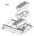
- FIG. 2 shows a further embodiment of the invention, wherein the sealing module 4 has electrical contact means 7 for coupling with the electrical contact means 8, 9 of the sub-components 2, 3.
- the contact means 8 of the subcomponent 2 are in FIG. 2 not directly visible.
- the sealing module 4 has electronic components.
- the sealing module 4 may include a printed circuit board with the entire required for the assembly e-lektronikkomponenten. Each time you replace the electronic components, eg. As caused by an error, by extension or by updating the electronics, then automatically replaced with the seal module and the seal.
- the invention thus relates to an assembly with at least two subcomponents 2, 3 and a sealing module.
- the assembly having at least two subcomponents 2, 3, which are composable to the assembly, at least one sealing module for receiving at least one seal 5, 6 which is insertable between in each case two subcomponents 2, 3.
Landscapes
- Engineering & Computer Science (AREA)
- Microelectronics & Electronic Packaging (AREA)
- Automation & Control Theory (AREA)
- Casings For Electric Apparatus (AREA)
Description
Die Erfindung betrifft eine Baugruppe mit mindestens zwei Teilkomponenten, welche zur Baugruppe zusammensetzbar sind, sowie ein Dichtungsmodul.The invention relates to an assembly with at least two subcomponents, which are assembled to the assembly, and a sealing module.
Die
Die
Die
Die
Die
Der Erfindung liegt die Aufgabe zugrunde, die Austauschbarkeit von Dichtungen bei aus mindestens zwei Teilkomponenten zusammengesetzten Baugruppen zu verbessern, insbesondere beim Vorliegen komplexer Dichtgeometrien.The invention has for its object to improve the interchangeability of seals in assembled from at least two sub-components assemblies, especially in the presence of complex sealing geometries.
Diese Aufgabe wird durch eine Baugruppe mit den im Anspruch 1 angegebenen Merkmalen gelöst. Die Baugruppe weist mindestens zwei Teilkomponenten auf, welche zur Baugruppe zusammensetzbar sind, wobei ein Dichtungsmodul zur Aufnahme mindestens von Dichtungen vorgesehen ist, welches zwischen jeweils zwei Teilkomponenten einsetzbar ist, dabei ist das Dichtungsmodul zwischen den zwei Teilkomponenten einer Baugruppe einsetzbar.This object is achieved by an assembly having the features specified in claim 1. The assembly has at least two subcomponents, which are assembled to the assembly, wherein a sealing module is provided for receiving at least seals, which can be used between two sub-components, while the sealing module between the two sub-components of an assembly can be used.
Insbesondere Baugruppen mit in höherer Schutzart ausgeführten Gehäusen werden üblicherweise verschiedenen Umgebungsbedingungen ausgesetzt. Solche Umgebungsbedingungen sind z.B. geprägt durch Flüssigkeiten, wie Öle, Säuren, Laugen oder auch durch klimatische Verhältnisse, wie besonders hohe oder niedrige Temperaturen. Um unterschiedlichsten Umgebungsbedingungen gerecht zu werden, werden üblicherweise zur Abdichtung der Gehäuse an die jeweilige Umgebungsbedingung angepasste O-Ringe hergestellt, welche aus verschiedenen Materialien bestehen. O-Ringe weisen den Vorteil auf, dass sie leicht tauschbar sind. Andererseits können bei komplexen Dichtgeometrien keine O-Ringe eingesetzt werden, da sich die O-Ringe in diesem Fall nur sehr schwer oder gar nicht montieren lassen. Beim Einsatz nicht tauschbarer Dichtungen ist bisher bei wechselnden Umgebungsbedingungen die Fertigung verschiedener Gehäuse mit jeweils an die Umgebungsbedingung angepassten Dichtungen erforderlich, wobei bei Bedarf das komplette Gehäuse getauscht werden muss. Der Erfindung liegt die Idee zugrunde, dass ein separates Dichtungsmodul zur Aufnahme mindestens einer Dichtung vorgesehen wird, wobei das Dichtungsmodul jeweils zwischen zwei Teilkomponenten einer aus Teilkomponenten zusammengesetzten Baugruppe einsetzbar ist. Auf diese Art können auch komplexe Dichtgeometrien realisiert werden. Für den Fall, dass die Baugruppe z.B. wegen Ausfalls getauscht werden muss, kann jeweils ein neues Dichtungsmodul mit einem neuen Dichtungssatz mitgeliefert werden.In particular, assemblies with higher protection rated housings are usually exposed to different environmental conditions. Such environmental conditions are for example characterized by liquids, such as oils, acids, alkalis or even by climatic conditions, such as particularly high or low temperatures. In order to meet a wide variety of environmental conditions, usually adapted to seal the housing to the respective environmental condition adapted O-rings, which consist of different materials. O-rings have the advantage that they are easily replaceable. On the other hand, O-rings can not be used with complex sealing geometries because in this case the O-rings are very difficult or impossible to assemble. When using non-exchangeable seals, the production of different housings with seals adapted to the ambient conditions has hitherto been necessary under changing environmental conditions, with the complete housing having to be replaced if necessary. The invention is based on the idea that a separate sealing module for receiving at least a seal is provided, wherein the sealing module can be used in each case between two sub-components of an assembly composed of sub-components. In this way, even complex sealing geometries can be realized. In the event that the module has to be replaced due to a failure, for example, a new sealing module with a new seal kit can be supplied.
Wenn gemäß einer vorteilhaften Ausgestaltung der Erfindung das Dichtungsmodul tauschbar ist, kann einerseits bei sich ändernden Umgebungsbedingungen die Baugruppe an diese Umgebungsbedingungen angepasst werden, andererseits kann eine Baugruppe mit verschiedenen für den jeweiligen Einsatzfall angepassten Dichtungsmodulen bereitgestellt werden. Vorteilhafterweise sind abhängig vom Einsatzfall Dichtungsmodule mit unterschiedlichen Dichtungen einsetzbar.If, according to an advantageous embodiment of the invention, the sealing module is exchangeable, the assembly can be adapted to these environmental conditions on the one hand with changing environmental conditions, on the other hand, an assembly can be provided with different adapted for each application sealing modules. Advantageously, depending on the application sealing modules with different seals can be used.
Die Handhabbarkeit der Erfindung lässt sich dadurch verbessern, dass die Dichtungen unverlierbar in das Dichtungsmodul eingebracht sind. Dies bietet insbesondere Vorteile gegenüber bisher verwendeten tauschbaren Dichtungen, wie z.B. O-Ringen.The handling of the invention can be improved by the fact that the seals are captively inserted into the sealing module. This offers particular advantages over hitherto used exchangeable seals, such as e.g. O-rings.
Gemäß einer weiteren vorteilhaften Ausgestaltung der Erfindung weist das Dichtungsmodul elektrische Kontaktmittel zur Kopplung mit elektrischen Kontaktmitteln der Teilkomponenten auf.According to a further advantageous embodiment of the invention, the sealing module has electrical contact means for coupling with electrical contact means of the subcomponents.
Wenn das Dichtungsmodul gemäß einer weiteren vorteilhaften Ausgestaltung der Erfindung elektronische Bauteile aufweist, wird bei einem gegebenenfalls erforderlichen Austausch dieser elektronischen Bauteile durch Tausch des Dichtungsmoduls automatisch auch die Dichtung getauscht.If the sealing module has electronic components according to a further advantageous embodiment of the invention, the seal is automatically replaced by replacement of the sealing module in an optionally required replacement of these electronic components.
Nachfolgend wird die Erfindung anhand der in den Figuren dargestellten Ausführungsbeispiele näher beschrieben und erläutert. Es zeigen:
- FIG 1
- eine Baugruppe mit zwei Teilkomponenten, jeweils im zusammengesetzten sowie im nicht zusammengesetzten Zustand,
- FIG 2
- eine Baugruppe mit zwei Teilkomponenten, wobei das Dichtungsmodul elektrische Kontaktmittel aufweist.
- FIG. 1
- an assembly with two sub-components, both in the assembled and unassembled state,
- FIG. 2
- an assembly with two sub-components, wherein the sealing module comprises electrical contact means.
Nicht dargestellt ist ein weiteres Ausführungsbeispiel der Erfindung, bei welchem das Dichtungsmodul 4 elektronische Bauteile aufweist. So kann das Dichtungsmodul 4 eine Leiterplatte mit den gesamten für die Baugruppe erforderlichen E-lektronikkomponenten enthalten. Bei jedem Tausch der Elektronikkomponenten, z. B. durch einen Fehlerfall, durch Erweiterung oder durch Aktualisierung der Elektronik bedingt, wird dann zusammen mit dem Dichtungsmodul automatisch auch die Dichtung getauscht.Not shown is another embodiment of the invention, in which the
Zusammengefasst betrifft die Erfindung somit eine Baugruppe mit mindestens zwei Teilkomponenten 2, 3 sowie ein Dichtungsmodul. Um die Austauschbarkeit von Dichtungen 5, 6 bei aus mindestens zwei Teilkomponenten 2, 3 zusammengesetzten Baugruppen zu verbessern, insbesondere beim Vorliegen komplexer Dichtgeometrien, wird vorgeschlagen, dass die Baugruppe mit mindestens zwei Teilkomponenten 2, 3, welche zur Baugruppe zusammensetzbar sind, mindestens ein Dichtungsmodul zur Aufnahme mindestens einer Dichtung 5, 6 aufweist, welches zwischen jeweils zwei Teilkomponenten 2, 3 einsetzbar ist.In summary, the invention thus relates to an assembly with at least two subcomponents 2, 3 and a sealing module. In order to improve the interchangeability of
Claims (9)
- Assembly (1) embodied as a peripheral module of a programmable logic controller of an industrial automation system with at least two component parts (2, 3), which are able to be combined to form the assembly (1), having a sealing module (4) to accept seals (5, 6) which is arranged between the two component parts (2, 3), wherein the sealing module (4) has corresponding receptacles on its upper and on its lower side to accept the seals (5, 6), wherein one component part (2) is embodied as a plug module for connection of external lines and the sealing module (4) has electrical contact means (7) for coupling with electrical contact means (8, 9) of the component parts (2, 3).
- Assembly according to claim 1,
characterised in that
the sealing module (4) is exchangeable. - Assembly according to claim 1 or 2,
characterised in that,
depending on the application, sealing modules (4) with different seals (5, 6) are able to be used. - Assembly according to one of the preceding claims,
characterised in that
the seals (5, 6) are fitted captive in the sealing module (4). - Assembly according to one of the preceding claims,
characterised in that
the component parts (2, 3) comprise housing parts (10, 11), wherein the housing parts (10, 11) are able to be assembled to form a housing (12) of the assembly (1) and the sealing module (4) is provided for sealing the housing (12). - Assembly according to one of the preceding claims,
characterised in that
the sealing module (4) has electronic components. - Sealing module according to one of the preceding claims,
characterised in that
the seals (5, 6) are fitted captive in the sealing module (4). - Sealing module according to one of the preceding claims,
characterised in that
the sealing module (4) is provided for sealing a housing (12) of the assembly (1). - Sealing module according to one of the preceding claims,
characterised in that
it has electronic components.
Applications Claiming Priority (2)
| Application Number | Priority Date | Filing Date | Title |
|---|---|---|---|
| DE102004018115A DE102004018115B4 (en) | 2004-04-14 | 2004-04-14 | Assembly with two subcomponents and sealing module |
| DE102004018115 | 2004-04-14 |
Publications (3)
| Publication Number | Publication Date |
|---|---|
| EP1587352A2 EP1587352A2 (en) | 2005-10-19 |
| EP1587352A3 EP1587352A3 (en) | 2009-04-15 |
| EP1587352B1 true EP1587352B1 (en) | 2012-06-06 |
Family
ID=34939032
Family Applications (1)
| Application Number | Title | Priority Date | Filing Date |
|---|---|---|---|
| EP05102272A Ceased EP1587352B1 (en) | 2004-04-14 | 2005-03-22 | Assembly made of at last two parts, as also sealed module |
Country Status (4)
| Country | Link |
|---|---|
| US (1) | US7616453B2 (en) |
| EP (1) | EP1587352B1 (en) |
| CN (1) | CN1684578A (en) |
| DE (1) | DE102004018115B4 (en) |
Families Citing this family (21)
| Publication number | Priority date | Publication date | Assignee | Title |
|---|---|---|---|---|
| DE102007060760A1 (en) * | 2007-12-17 | 2009-06-18 | Giesecke & Devrient Gmbh | Sealing of housings by means of sealing compound |
| DE102011110182A1 (en) * | 2011-08-09 | 2013-02-14 | Pilz Gmbh & Co. Kg | Modular control device |
| USD733665S1 (en) * | 2011-12-16 | 2015-07-07 | Siemens Aktiengesellschaft | Programmable logic controller (PLC) |
| DE102012213258A1 (en) * | 2012-07-27 | 2014-01-30 | Siemens Aktiengesellschaft | connection system |
| DE102012213281B4 (en) * | 2012-07-27 | 2024-06-06 | Phoenix Contact Gmbh & Co. Kg | Fieldbus modular system, carrier module and fieldbus module |
| GB2508402B (en) * | 2012-11-30 | 2015-05-27 | Control Tech Ltd | A mount for electrical equipment |
| US10006557B2 (en) | 2013-03-15 | 2018-06-26 | Asco, L.P. | Valve manifold circuit board with serial communication and control circuit line |
| CA2902643C (en) | 2013-03-15 | 2019-04-02 | Numatics, Incorporated | Valve manifold circuit board with serial communication circuit line |
| DE102013112117A1 (en) | 2013-11-04 | 2015-05-07 | Phoenix Contact Gmbh & Co. Kg | Functional component for a component assembly system |
| DE102013112101B4 (en) * | 2013-11-04 | 2018-05-09 | Phoenix Contact Gmbh & Co. Kg | Components Mounting System |
| US10568228B2 (en) * | 2017-06-02 | 2020-02-18 | Johnson Controls Technology Company | Adapter assembly for field controller units |
| FR3070223B1 (en) * | 2017-08-17 | 2019-08-30 | Etablissements Georges Renault | BACKGROUND OF CONTACT BASKET BETWEEN IMPROVED ADJACENT MODULE |
| DE102018133647A1 (en) | 2018-12-28 | 2020-07-02 | Beckhoff Automation Gmbh | Control cabinet system consisting of basic module and function modules as well as function module |
| DE102018133646A1 (en) | 2018-12-28 | 2020-07-02 | Beckhoff Automation Gmbh | Basic module and function module for a control cabinet system |
| DE102018133657A1 (en) | 2018-12-28 | 2020-07-02 | Beckhoff Automation Gmbh | BASIC MODULE AND FUNCTIONAL MODULE FOR A CONTROL CABINET SYSTEM AND CONTROL CABINET SYSTEM |
| USD918149S1 (en) * | 2019-01-09 | 2021-05-04 | Wago Verwaltungsgesellschaft Mbh | Control device |
| DE102019106082B4 (en) * | 2019-03-11 | 2021-06-24 | Beckhoff Automation Gmbh | CABINET SYSTEM WITH SEAL INSERT |
| CN110572974B (en) * | 2019-09-18 | 2024-05-10 | 深圳市科伦特电子有限公司 | Waterproof construction and LED display screen |
| DE202020001851U1 (en) * | 2020-04-30 | 2020-06-08 | Siemens Aktiengesellschaft | Electrical device with a sealing device |
| FR3122546B1 (en) * | 2021-04-28 | 2023-05-12 | Openindus | Modular electronic assembly |
| DE102022113306B4 (en) * | 2022-05-25 | 2024-02-29 | Beckhoff Automation Gmbh | AUTOMATION PLATFORM |
Family Cites Families (18)
| Publication number | Priority date | Publication date | Assignee | Title |
|---|---|---|---|---|
| US4943686A (en) | 1988-04-18 | 1990-07-24 | Andrzej Kucharek | Seal frame and method of use |
| US5107404A (en) * | 1989-09-14 | 1992-04-21 | Astec International Ltd. | Circuit board assembly for a cellular telephone system or the like |
| FR2655809B1 (en) | 1989-12-13 | 1996-08-09 | Siemens Automotive Sa | PROCESS FOR ASSEMBLING A PROTECTIVE HOUSING, PARTICULARLY AN ELECTRONIC MODULE, AND PROTECTIVE HOUSING OBTAINED BY IMPLEMENTING THIS PROCESS. |
| JP2829796B2 (en) * | 1991-05-24 | 1998-12-02 | 松下電器産業株式会社 | Electronic equipment housing |
| EP1316728B1 (en) * | 1991-09-10 | 2005-08-17 | Smc Kabushiki Kaisha | Fluid pressure apparatus |
| DE9321190U1 (en) | 1993-09-13 | 1998-01-15 | Duerrwaechter E Dr Doduco | Component set for a housing made of plastic for receiving electrical components |
| DE4340108C3 (en) * | 1993-11-22 | 2003-08-14 | Emi Tec Elektronische Material | Shielding element and method for its production |
| JP3486238B2 (en) * | 1994-09-21 | 2004-01-13 | Smc株式会社 | Switching valve |
| DE29507119U1 (en) * | 1995-04-27 | 1995-07-20 | Bürkert Werke GmbH & Co., 74653 Ingelfingen | Modular electrical part for a valve block |
| SE507939C2 (en) * | 1996-04-23 | 1998-08-03 | Asea Brown Boveri | Device for transmitting electrical signals |
| US5761042A (en) * | 1996-10-02 | 1998-06-02 | Motorola, Inc. | Radio frequency compatible multi-board cluster |
| JPH11141715A (en) * | 1997-11-07 | 1999-05-28 | Smc Corp | Current feeding device for solenoid valve assembly body |
| JP4524872B2 (en) * | 2000-07-07 | 2010-08-18 | Smc株式会社 | Signal input / output device |
| JP2002198664A (en) | 2000-12-26 | 2002-07-12 | Seiko Instruments Inc | Portable electronic apparatus |
| JP4125875B2 (en) * | 2001-04-13 | 2008-07-30 | 日東電工株式会社 | Sealant for electrical and electronic equipment |
| JP4471541B2 (en) * | 2001-07-18 | 2010-06-02 | 旭有機材工業株式会社 | Constant pressure regulator |
| EP1359649A1 (en) * | 2002-05-03 | 2003-11-05 | Trumpf Werkzeugmaschinen GmbH + Co. KG | Assembly system especially for an electrical cabinet |
| US7245497B2 (en) * | 2005-05-17 | 2007-07-17 | Itt Manufacturing Enterprises, Inc. | Modular electronics enclosure |
-
2004
- 2004-04-14 DE DE102004018115A patent/DE102004018115B4/en not_active Revoked
-
2005
- 2005-03-22 EP EP05102272A patent/EP1587352B1/en not_active Ceased
- 2005-04-05 US US11/098,816 patent/US7616453B2/en not_active Expired - Fee Related
- 2005-04-07 CN CNA2005100638117A patent/CN1684578A/en active Pending
Also Published As
| Publication number | Publication date |
|---|---|
| EP1587352A2 (en) | 2005-10-19 |
| DE102004018115A1 (en) | 2005-11-10 |
| US20050231931A1 (en) | 2005-10-20 |
| CN1684578A (en) | 2005-10-19 |
| US7616453B2 (en) | 2009-11-10 |
| DE102004018115B4 (en) | 2011-09-15 |
| EP1587352A3 (en) | 2009-04-15 |
Similar Documents
| Publication | Publication Date | Title |
|---|---|---|
| EP1587352B1 (en) | Assembly made of at last two parts, as also sealed module | |
| DE102006049631B4 (en) | Signal input / output device | |
| DE102009046014A1 (en) | Electrical connector housing and method of assembling same | |
| EP3138161B1 (en) | Contact element for an electric connection, copper strip for producing a plurality of contact elements | |
| DE102015110070A1 (en) | Electrical connection arrangement | |
| DE112008001092T5 (en) | Protective cover for a circuit carrier | |
| DE202014101491U1 (en) | Bus-compatible, connectable and / or functional module | |
| EP2697461B1 (en) | Motor vehicle door lock housing | |
| EP3663494A1 (en) | Motor vehicle door lock | |
| DE102013221239B4 (en) | Control device | |
| EP0068482A1 (en) | Control system, particularly for automatic manufacturing plants | |
| EP2305010B1 (en) | Electrical circuit arrangement | |
| DE102005027852A1 (en) | Arrangement and method for the electrical connection of an electronic circuit in a housing | |
| EP1976072B1 (en) | Bus connector with at least two cable connections for bus lines | |
| WO2014037173A1 (en) | Arrangement of an electric control device on a circuit board | |
| DE202018101278U1 (en) | Connector module for a modular industrial connector for transmitting high data rates | |
| DE202011102353U1 (en) | Safety arrangement, in particular for a motor vehicle electrical system | |
| EP2870838A2 (en) | Motor vehicle component support and method for the production thereof | |
| EP0669794B1 (en) | Enclosure with a main body and a cover | |
| DE202006020788U1 (en) | Electrical or electronic device | |
| DE102004007230B4 (en) | Housing with liquid-tight electrical feedthrough | |
| DE4405578B4 (en) | Electronic assembly | |
| DE60223782T2 (en) | Combination of front panels | |
| DE10353139B4 (en) | Stackable modular housing system and method of making the same | |
| EP3084897B1 (en) | Electrical assembly |
Legal Events
| Date | Code | Title | Description |
|---|---|---|---|
| PUAI | Public reference made under article 153(3) epc to a published international application that has entered the european phase |
Free format text: ORIGINAL CODE: 0009012 |
|
| AK | Designated contracting states |
Kind code of ref document: A2 Designated state(s): AT BE BG CH CY CZ DE DK EE ES FI FR GB GR HU IE IS IT LI LT LU MC NL PL PT RO SE SI SK TR |
|
| AX | Request for extension of the european patent |
Extension state: AL BA HR LV MK YU |
|
| PUAL | Search report despatched |
Free format text: ORIGINAL CODE: 0009013 |
|
| AK | Designated contracting states |
Kind code of ref document: A3 Designated state(s): AT BE BG CH CY CZ DE DK EE ES FI FR GB GR HU IE IS IT LI LT LU MC NL PL PT RO SE SI SK TR |
|
| AX | Request for extension of the european patent |
Extension state: AL BA HR LV MK YU |
|
| 17P | Request for examination filed |
Effective date: 20090918 |
|
| AKX | Designation fees paid |
Designated state(s): DE FR GB IT |
|
| 17Q | First examination report despatched |
Effective date: 20110324 |
|
| REG | Reference to a national code |
Ref country code: DE Ref legal event code: R079 Ref document number: 502005012783 Country of ref document: DE Free format text: PREVIOUS MAIN CLASS: H05K0007140000 Ipc: H05K0005060000 |
|
| GRAP | Despatch of communication of intention to grant a patent |
Free format text: ORIGINAL CODE: EPIDOSNIGR1 |
|
| RIC1 | Information provided on ipc code assigned before grant |
Ipc: H05K 5/06 20060101AFI20111129BHEP Ipc: H05K 7/14 20060101ALI20111129BHEP |
|
| GRAS | Grant fee paid |
Free format text: ORIGINAL CODE: EPIDOSNIGR3 |
|
| GRAA | (expected) grant |
Free format text: ORIGINAL CODE: 0009210 |
|
| AK | Designated contracting states |
Kind code of ref document: B1 Designated state(s): DE FR GB IT |
|
| REG | Reference to a national code |
Ref country code: GB Ref legal event code: FG4D Free format text: NOT ENGLISH |
|
| REG | Reference to a national code |
Ref country code: DE Ref legal event code: R096 Ref document number: 502005012783 Country of ref document: DE Effective date: 20120802 |
|
| RAP2 | Party data changed (patent owner data changed or rights of a patent transferred) |
Owner name: SIEMENS AKTIENGESELLSCHAFT |
|
| PLBE | No opposition filed within time limit |
Free format text: ORIGINAL CODE: 0009261 |
|
| STAA | Information on the status of an ep patent application or granted ep patent |
Free format text: STATUS: NO OPPOSITION FILED WITHIN TIME LIMIT |
|
| 26N | No opposition filed |
Effective date: 20130307 |
|
| REG | Reference to a national code |
Ref country code: DE Ref legal event code: R097 Ref document number: 502005012783 Country of ref document: DE Effective date: 20130307 |
|
| REG | Reference to a national code |
Ref country code: FR Ref legal event code: PLFP Year of fee payment: 12 |
|
| REG | Reference to a national code |
Ref country code: FR Ref legal event code: PLFP Year of fee payment: 13 |
|
| REG | Reference to a national code |
Ref country code: FR Ref legal event code: PLFP Year of fee payment: 14 |
|
| PGFP | Annual fee paid to national office [announced via postgrant information from national office to epo] |
Ref country code: GB Payment date: 20190313 Year of fee payment: 15 Ref country code: FR Payment date: 20190322 Year of fee payment: 15 Ref country code: IT Payment date: 20190327 Year of fee payment: 15 |
|
| PGFP | Annual fee paid to national office [announced via postgrant information from national office to epo] |
Ref country code: DE Payment date: 20190517 Year of fee payment: 15 |
|
| REG | Reference to a national code |
Ref country code: DE Ref legal event code: R119 Ref document number: 502005012783 Country of ref document: DE |
|
| PG25 | Lapsed in a contracting state [announced via postgrant information from national office to epo] |
Ref country code: DE Free format text: LAPSE BECAUSE OF NON-PAYMENT OF DUE FEES Effective date: 20201001 |
|
| GBPC | Gb: european patent ceased through non-payment of renewal fee |
Effective date: 20200322 |
|
| PG25 | Lapsed in a contracting state [announced via postgrant information from national office to epo] |
Ref country code: GB Free format text: LAPSE BECAUSE OF NON-PAYMENT OF DUE FEES Effective date: 20200322 |
|
| PG25 | Lapsed in a contracting state [announced via postgrant information from national office to epo] |
Ref country code: IT Free format text: LAPSE BECAUSE OF NON-PAYMENT OF DUE FEES Effective date: 20200322 |
|
| PG25 | Lapsed in a contracting state [announced via postgrant information from national office to epo] |
Ref country code: FR Free format text: LAPSE BECAUSE OF NON-PAYMENT OF DUE FEES Effective date: 20200331 |