EP1587198A1 - Cover frame assembly - Google Patents
Cover frame assembly Download PDFInfo
- Publication number
- EP1587198A1 EP1587198A1 EP05005869A EP05005869A EP1587198A1 EP 1587198 A1 EP1587198 A1 EP 1587198A1 EP 05005869 A EP05005869 A EP 05005869A EP 05005869 A EP05005869 A EP 05005869A EP 1587198 A1 EP1587198 A1 EP 1587198A1
- Authority
- EP
- European Patent Office
- Prior art keywords
- profile
- module
- cover
- frame
- modules
- Prior art date
- Legal status (The legal status is an assumption and is not a legal conclusion. Google has not performed a legal analysis and makes no representation as to the accuracy of the status listed.)
- Withdrawn
Links
Images


Classifications
-
- H—ELECTRICITY
- H02—GENERATION; CONVERSION OR DISTRIBUTION OF ELECTRIC POWER
- H02G—INSTALLATION OF ELECTRIC CABLES OR LINES, OR OF COMBINED OPTICAL AND ELECTRIC CABLES OR LINES
- H02G3/00—Installations of electric cables or lines or protective tubing therefor in or on buildings, equivalent structures or vehicles
- H02G3/02—Details
- H02G3/08—Distribution boxes; Connection or junction boxes
- H02G3/14—Fastening of cover or lid to box
Definitions
- the invention relates to a cover frame structure for installable under plaster electrical Equipment.
- the invention is therefore based on the object, a cover frame structure for under Putz installable electrical equipment available for any number of electrical installation devices in flush-mounted multiple combinations can be realized and which are also used with minor deviation of mutual can spacing can.
- a cover frame structure in the form of a MehrfachAbdeckrahmens made available in modular design, where for the construction of each any number of cans to be covered advantageously requires only two types of modules be a basic part module and a middle part module.
- the basic module serves as Start and end of a multiple cover frame, while the middle part module in any number between two basic modules provided by the Steckanschlußabête can be used so that not just any number of single cover frame, but also advantageously a variable insertion depth below Cover the area between adjacent modules can be enabled.
- the provided as the beginning and end piece base modules are preferably Common parts and offset by 180 ° to each other congruent, while the centerpiece acting Mitteilteilmodule each other and to the beginning or end pieces or Basic modules are compatible.
- a beneficial nested plug contour with simultaneous overlap in the region of the joint between the individual modules can be advantageous over a certain range of Set module or device spacing variable.
- This setting can preferably infinitely frictional or with clamping engagement or in certain locking steps of 0.5 mm, for example, with appropriate locking.
- the plug contours each Steckanschlußabitess with a certain excess made such that the Multiple frame in the desired configuration held together by clamping force becomes.
- cover frame structure according to the invention inaccurate installation of the device inserts, as a variable continuously adjustable device or Module spacing can be made possible, with each individual cover frame module on can center the device insert mounted underneath.
- inventive concept several cover frame modules a single image for the generated Mehrfachabdeckrahmen, even if slightly different device distances available. For example, a stepless compensation of the can spacing of 70 is advantageous possible up to 75 mm.
- Another significant advantage of the Abdeckrahmen excessives invention is a lower storage and stockpiling, because only two different modules are required. Also on site is the use of Abdeckrahmen excessives as Mehrfachabdeckrahmen cheap because locally any number of modules to a required Multiple cover frame can be plugged together.
- the plug connection profiles of two juxtaposed frame modules have according to a preferred further embodiment of the invention alternately overlapping cover profiles with the result that always a frame-side cover even greater distances from below Plaster installed electrical equipment is possible and always a uniform Cover frame picture arises.
- each Plug connection portion with a preferably laterally projecting male, a adjoining, up to half of the page extending flat projecting Cover profile, a complementary recess for receiving the flat Cover profile of the next module and a complementary receiving profile for the Insert profile of the next module provided.
- the cross section of the Einsteckprofile and the complementary receiving profiles is possible in any suitable profile shape, wherein only must be ensured that a frictional or latching mutual engagement is present with sufficient guidance and the male profile of the flat design of the Intermediate area fits between two modules.
- the width of the frame each module on each side where a male terminal portion is formed such as on the Half of the other frame width reduced. This is when directly joined together Modules a cover frame with constant frame width over the entire circumference of each Module realized.
- the base part module and the middle part module are preferably approximately square formed, wherein the male profile preferably formed in the edge region of each module is. Furthermore, it is preferably provided that the male profile a flat top has, which is flush with the surface of the adjoining cover profile.
- FIG. 1 shows a basic part module 10 in a perspective view, which is used as a starting point. and is provided as an end piece for a Mehrfachabdeckrahmen inconvenience.
- the Base module 10 is approximately square with a Endrahmenprofilabites 11, two Side frame profile sections 12 and 13 and a terminal frame profile section 14 formed, which adjoin one another and limit a frame cutout 15, which is for the Use of the electrical flush-mounted device is provided and the one circumferential Retaining edge 16 with installation recesses 17 for fixing the cover frame by means having a circumferential edge of the installation device.
- the width of the frame profile sections 11 to 13 is approximately equal, while the Frame section 14 only about half the width of the frame profile sections 11 and 12 has.
- the frame profile sections are at their top in this Embodiment just formed, wherein the frame profile sections 11 and 14th slightly raised above the surface of the frame profile sections 12 and 13 formed are.
- the plug-in connection section 18 consists of an edge-projecting male profile 19, an up to half of the terminal side extending flat protruding Cover profile 20, a complementary recess 21 for receiving the flat Cover profile of the next module, and a Aus.profil 22, which is complementary to the outer contour of the Einsteckprofils 19 is formed.
- the for the connector with provided a complementary formed plug connection section Connecting elements 19, 20, 21 and 22 are below the upper frame surface of Frame profile sections 11 to 13 are arranged, wherein the arrangement is made such that the Mutually provided cover profiles 20 the distance between two Side profile sections 14 bridged abutting, so that even at each other spaced side profile frame sections 14 always gives a closed frame image. This also contributes to the top and outside training of Einsteckprofils 19.
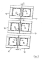
- FIG. 2 various double cover frame assemblies with different ones are shown bridged distances between the cover frame openings 15 and the mutually pointing frame profile sections 14 shown, wherein the different distances at the multiple frames are indicated by a, b and c.
- the double cover frame construction in FIG. 2 consists of two basic submodules 10, as shown in FIG complementary plug-in connection sections 18 are plugged together at different depths.
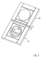
- FIG. 3 clearly shows a double cover frame construction according to the invention, which is used for Cover a socket and an adjacent switch is used, the Device distance is increased compared to the intended distance and the gap between the modules on the mutually complementary plug connection sections the width c is bridged.
- FIG. 4 shows the modules for the construction of a triple cover frame.
- the modules exist from the two end-side base part modules 10 and a middle part module 30.
- Das Middle part module 30 is provided with two opposite side profile sections 31 and 32 and two side profile sections 33 and 34 are formed, which, like the module 10, Plug-in connection sections 18 which on the module 30 rotationally symmetrical in such a way are arranged to be complementary plug-in terminal portions 18 of the Basic part modules 10 and plug-in connection sections of further middle part modules 30, as in Figures 6 and 7, fit.
- Figure 5 shows the structure of the cover according to Figure 4 in a mated Condition, wherein the distances between the side frame profile sections 14 and 33 with e and the side frame profile sections 14 and 34 are designated d.
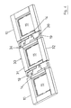
- FIG. 6 and 7 show a further embodiment of an inventive Frame construction with a total of five modules, two end modules 10 and three in between arranged Mitteilteilmodulen 30.
- the modules 10 and 30 are as in the previous illustrated embodiments with mutually complementary Plug connection sections 18 formed, the mutually overlapping cover profiles 19, 20, see Figure 1, have.
- FIG. 7 shows the five-fold cover frame assembly of modules 10 and Figure 30 in accordance with Figure 6 in an assembled state, with different distances between the can openings 15, which are to be covered with the modules 10 and 13, with the Letters f to i are given.
- the distance between two modules also by provided incremental locking of the male profile in the complementary recess be, and by the dimensionally stable design of the Einsteckprofile 19 and the associated complementary recesses 22 is complementary to the mutual investment management the flat cover 20 also a great dimensional stability of the invention Cover frame construction realized even with longer designs.
Landscapes
- Engineering & Computer Science (AREA)
- Architecture (AREA)
- Civil Engineering (AREA)
- Structural Engineering (AREA)
- Casings For Electric Apparatus (AREA)
Abstract
Description
Die Erfindung betrifft einen Abdeckrahmenaufbau für unter Putz installierbare elektrische Geräte.The invention relates to a cover frame structure for installable under plaster electrical Equipment.
Wenn elektrische Geräte, wie beispielsweise Steckdosen, Schalter und dergleichen unter Putz installiert sind, werden sie anschließend mittels eines Abdeckrahmens abgedeckt. Dieser Abdeckrahmen dient auch dazu, mehrere nebeneinander angeordnete elektrische Geräte gleichzeitig abzudecken. In der Praxis besteht jedoch das Problem, daß der Abstand zwischen Wanddosen, in die elektrische Geräte unter Putz eingesetzt werden, bei ungenauer Montage oder durch Einputzen variieren kann. Dies führt dazu, daß bei Mehrfachkombinationen von elektrischen Geräten der wechselseitige Abstand unterschiedlich groß ausfallen kann und dann das Problem besteht, daß Mehrfachabdeckrahmen, die über einen festgelegten Abstand der Gehäuseausschnitte verfügen (Normmaß 71 mm) nicht richtig passen und bei ihrer nicht deckungsgleichen Montage Funktionsbeeinträchtigungen auftreten können. Bisher ist in solchen Fällen eine zeitaufwendige Korrektur der Vorinstallation erforderlich, um jeweils den durch den Geräteausschnitt in dem Mehrfachabdeckrahmen vorgegebenen wechselseitigen Abstand der elektrischen Geräte, wie Schalter, Steckdosen und dergleichen genau herzustellen, wodurch sich nicht nur der Installationsaufwand, sondern auch die Installationskosten erheblich vergrößern.When electrical appliances, such as sockets, switches and the like under plaster are installed, they are then covered by a cover frame. This Cover frame also serves several juxtaposed electrical devices cover at the same time. In practice, however, there is the problem that the distance between Wall boxes in which electrical appliances are used under plaster, in case of inaccurate installation or by plastering may vary. This results in multiple combinations of electrical devices the mutual distance can turn out to be different and big then the problem is that Mehrfachabdeckrahmen over a specified distance the housing cut-outs (standard dimension 71 mm) do not fit properly and with their not congruent assembly malfunction may occur. So far is in Such cases require a time-consuming correction of the pre-installation, in each case the through the device cutout in the Mehrfachabdeckrahmen predetermined reciprocal Distance of the electrical equipment, such as switches, sockets and the like exactly produce, which not only the installation costs, but also the Increase installation costs significantly.
Hinzu kommt, daß jeweils für jede Anzahl kombinierter elektrischer Geräte spezielle Abdeckrahmen erforderlich sind, deren Herstellung sich bei Rahmen mit mehr als drei Geräteausschnitten in der Regel wegen Unwirtschaftlichkeit nicht amortisiert.In addition, each for each number of combined electrical appliances special Cover frames are required, the production of which in frames with more than three Device cutouts are usually not amortized due to inefficiency.
Der Erfindung liegt demgemäß die Aufgabe zugrunde, einen Abdeckrahmenaufbau für unter Putz installierbare elektrische Geräte verfügbar zu machen, der für eine beliebige Anzahl von elektrischen Installationsgeräten in Unterputz-Mehrfachkombinationen realisiert werden und der auch bei geringfügiger Abweichung wechselseitiger Dosenabstände eingesetzt werden kann. The invention is therefore based on the object, a cover frame structure for under Putz installable electrical equipment available for any number of electrical installation devices in flush-mounted multiple combinations can be realized and which are also used with minor deviation of mutual can spacing can.
Erfindungsgemäß wird diese Aufgabe durch die im Patentanspruch 1 genannten Merkmale gelöst.According to the invention, this object is achieved by the features mentioned in patent claim 1 solved.
Bevorzugte Merkmale, die die Erfindung vorteilhaft weiterbilden, sind den nachgeordneten Patentansprüchen zu entnehmen.Preferred features which advantageously further develop the invention are the downstream ones To claim.
Vorteilhaft wird aufgrund der Erfindung ein Abdeckrahmenaufbau in Form eines MehrfachAbdeckrahmens in Modulbauweise verfügbar gemacht, wobei für den Aufbau jeder beliebigen Anzahl von abzudeckenden Dosen vorteilhaft nur zwei Modularten benötigt werden, ein Grundteilmodul und ein Mittelteilmodul. Das Grundteilmodul dient dabei als Anfangs- und als Endstück eines Mehrfachabdeckrahmens, während das Mittelteilmodul in beliebiger Zahl zwischen zwei Grundmodulen durch die vorgesehenen Steckanschlußabschnitte so eingesetzt werden kann, daß nicht nur eine beliebige Anzahl von einzelnen Abdeckungsrahmen, sondern auch vorteilhaft eine veränderbare Einstecktiefe unter Abdeckung des Bereichs zwischen benachbarten Modulen ermöglicht werden kann.Advantageously, due to the invention, a cover frame structure in the form of a MehrfachAbdeckrahmens made available in modular design, where for the construction of each any number of cans to be covered advantageously requires only two types of modules be a basic part module and a middle part module. The basic module serves as Start and end of a multiple cover frame, while the middle part module in any number between two basic modules provided by the Steckanschlußabschnitte can be used so that not just any number of single cover frame, but also advantageously a variable insertion depth below Cover the area between adjacent modules can be enabled.
Die als Anfangs- und als Endstück vorgesehenen Grundteilmodule sind vorzugsweise Gleichteile und um 180° versetzt zueinander deckungsgleich, während die als Mittelstück fungierenden Mitteilteilmodule zueinander und zu den Anfangs- bzw. Endstücken bzw. Grundmodulen kompatibel sind. Durch die Ausbildung eines vorteilhaften ineinanderfügbaren Steckkontur mit gleichzeitiger Überlappung im Bereich der Stoßstelle zwischen den einzelnen Modulen läßt sich vorteilhaft über einen bestimmten Bereich der Modul- bzw. Geräteabstand variabel einstellen. Diese Einstellung kann vorzugsweise stufenlos reibschlüssig bzw. mit klemmendem Eingriff oder auch in bestimmten Raststufen von beispielsweise 0,5 mm mit entsprechenden Verrastungen vorgenommen werden.The provided as the beginning and end piece base modules are preferably Common parts and offset by 180 ° to each other congruent, while the centerpiece acting Mitteilteilmodule each other and to the beginning or end pieces or Basic modules are compatible. By training a beneficial nested plug contour with simultaneous overlap in the region of the joint between the individual modules can be advantageous over a certain range of Set module or device spacing variable. This setting can preferably infinitely frictional or with clamping engagement or in certain locking steps of 0.5 mm, for example, with appropriate locking.
Für die reibschlüssige Steckverbindung sind vorteilhaft die Steckkonturen jedes Steckanschlußabschnitts mit einem bestimmten Übermaß derart hergestellt, daß der Mehrfachrahmen in der gewünschten Konfiguration durch Klemmkraft zusammengehalten wird. For the frictional connector advantageously the plug contours each Steckanschlußabschnitts with a certain excess made such that the Multiple frame in the desired configuration held together by clamping force becomes.
Besonders vorteilhaft ist der Einsatz des erfindungsgemäßen Abdeckrahmenaufbaus bei ungenauer Installation der Geräteeinsätze, da ein variabler stufenlos anpaßbarer Geräte- bzw. Modulabstand ermöglicht werden kann, wobei sich jeder einzelne Abdeckrahmenmodul auf den darunter montierten Geräteeinsatz zentrieren kann. Vorteilhaft ergeben durch das erfindungsgemäße Konzept mehrere Abdeckrahmenmodule ein einheitliches Bild für den erzeugten Mehrfachabdeckrahmen, auch wenn geringfügig abweichende Geräteabstände vorliegen. Vorteilhaft ist beispielsweise ein stufenloser Ausgleich des Dosenabstand von 70 bis 75 mm möglich.Particularly advantageous is the use of the cover frame structure according to the invention inaccurate installation of the device inserts, as a variable continuously adjustable device or Module spacing can be made possible, with each individual cover frame module on can center the device insert mounted underneath. Advantageously revealed by the inventive concept several cover frame modules a single image for the generated Mehrfachabdeckrahmen, even if slightly different device distances available. For example, a stepless compensation of the can spacing of 70 is advantageous possible up to 75 mm.
Ein weiterer wesentlicher Vorteil des erfindungsgemäßen Abdeckrahmenaufbaus ist eine geringere Lager- und Vorratshaltung, weil nur zwei verschiedene Module erforderlich sind. Auch bauseitig ist der Einsatz des Abdeckrahmenaufbaus als Mehrfachabdeckrahmen dahingehend günstig, weil vor Ort jede beliebige Anzahl der Module zu einem erforderlichen Mehrfach-Abdeckrahmen zusammengesteckt werden kann.Another significant advantage of the Abdeckrahmenaufbaus invention is a lower storage and stockpiling, because only two different modules are required. Also on site is the use of Abdeckrahmenaufbaus as Mehrfachabdeckrahmen cheap because locally any number of modules to a required Multiple cover frame can be plugged together.
Die Steckanschlußprofile zweier aneinandergesteckter Rahmenmodule weisen gemäß einer bevorzugten weiteren Ausgestaltung der Erfindung wechselseitig überlappende Abdeckprofile mit der Folge auf, daß stets eine rahmenseitige Abdeckung auch größerer Abstände von unter Putz installierten elektrischen Geräten möglich ist und stets ein einheitliches Abdeckrahmenbild entsteht.The plug connection profiles of two juxtaposed frame modules have according to a preferred further embodiment of the invention alternately overlapping cover profiles with the result that always a frame-side cover even greater distances from below Plaster installed electrical equipment is possible and always a uniform Cover frame picture arises.
Gemäß einer bevorzugten weiteren Ausgestaltung der Erfindung ist jeder Steckanschlußabschnitt mit einem vorzugsweise seitlich vorstehenden Einsteckprofil, einem sich daran anschließenden, bis zur Hälfte der Seite erstreckenden flächig vorstehenden Abdeckprofil, einer komplementären Ausnehmung für die Aufnahme des flächigen Abdeckprofils des nächsten Moduls und einem komplementären Aufnahmeprofil für das Einsteckprofil des nächsten Moduls versehen. Der Querschnitt der Einsteckprofile und der komplementären Aufnahmeprofile ist dabei in jeder geeigneten Profilform möglich, wobei nur gewährleistet sein muß, daß ein reibschlüssiger oder verrastender wechselseitiger Eingriff mit ausreichender Führung vorliegt und das Einsteckprofil an die flächige Gestaltung des Zwischenbereichs zwischen zwei Modulen paßt. According to a preferred further embodiment of the invention, each Plug connection portion with a preferably laterally projecting male, a adjoining, up to half of the page extending flat projecting Cover profile, a complementary recess for receiving the flat Cover profile of the next module and a complementary receiving profile for the Insert profile of the next module provided. The cross section of the Einsteckprofile and the complementary receiving profiles is possible in any suitable profile shape, wherein only must be ensured that a frictional or latching mutual engagement is present with sufficient guidance and the male profile of the flat design of the Intermediate area fits between two modules.
Damit vorteilhaft ein einheitliches Erscheinungsbild gewahrt ist, ist nach einer weiteren vorteilhaften Ausgestaltung der Erfindung vorgesehen, daß die Steck- bzw. Verbindungsabschnitte jedes Steckanschlußprofils unterhalb der Abdeckrahmenoberfläche angeordnet sind. Hierdurch läßt sich durch ein hälftiges Ineinanderschieben dieses Gesamtbild für den Abdeckrahmen beibehalten.So that a uniform appearance is advantageous, is after another advantageous embodiment of the invention provided that the plug or Connecting portions of each plug connection profile below the cover frame surface are arranged. This can be by a half telescoping slide this Maintain overall picture for the cover frame.
Gemäß einer weiteren bevorzugten Ausgestaltung der Erfindung ist die Breite des Rahmens jedes Moduls an jeder Seite, an der ein Einsteckanschlußabschnitt gebildet ist, etwa auf die Hälfte der sonstigen Rahmenbreite reduziert. Hierdurch wird bei direkt aneinandergefügten Modulen ein Abdeckrahmen mit konstanter Rahmenbreite über den gesamten Umfang jedes Moduls verwirklicht.According to a further preferred embodiment of the invention, the width of the frame each module on each side where a male terminal portion is formed, such as on the Half of the other frame width reduced. This is when directly joined together Modules a cover frame with constant frame width over the entire circumference of each Module realized.
Das Grundteilmodul und das Mittelteilmodul sind bevorzugt annähernd quadratisch ausgebildet, wobei das Einsteckprofil vorzugsweise im Randbereich jedes Moduls gebildet ist. Weiterhin ist bevorzugt vorgesehen, daß das Einsteckprofil eine flächige Oberseite aufweist, die bündig mit der Fläche des daran angrenzenden Abdeckprofils verläuft.The base part module and the middle part module are preferably approximately square formed, wherein the male profile preferably formed in the edge region of each module is. Furthermore, it is preferably provided that the male profile a flat top has, which is flush with the surface of the adjoining cover profile.
Nachfolgend wird die Erfindung unter Bezugnahme auf die beigefügten Zeichnungen näher erläutert. Es zeigen:
- Figur 1
- eine schräge perspektivische Draufsicht auf ein Ausführungsbeispiel eines Grundteilmoduls;
- Figur 2
- drei verschiedene Zweifachabdeckrahmenaufbauten mit überbrückten unterschiedlichen Rahmenöffnungsabständen;
- Figur 3
- eine Darstellung eines Zweifachabdeckrahmenaufbaus, der zwei nebeneinander angeordnete Unterputzgeräte mit größerem Geräteabstand als nach dem Standard vorgesehen abdeckt;
- Figur 4
- eine perspektivische Draufsicht auf zwei Grundteilmodule und ein Mittelteilmodul vor ihrem Zusammenstecken zu einem Mehrfachabdeckrahmen;
- Figur 5
- die Module von Figur 4 nach dem Zusammenstecken, wobei zwischen benachbarten Modulen unterschiedliche Abstände überbrückt werden;
- Figur 6
- einen Abdeckrahmenaufbau für das Abdecken von fünf elektrischen Unterputzinstallationsgeräten vor dem Zusammenstecken der einzelnen Module; und
- Figur 7
- den Fünffachabdeckrahmen mit zusammengesteckten Modulen gemäß Figur 6, wobei zwischen aneinandergrenzenden Modulen unterschiedliche Abstände überbrückt werden.
- FIG. 1
- an oblique perspective top view of an embodiment of a base module;
- FIG. 2
- three different dual cover frame assemblies with bridged different frame opening distances;
- FIG. 3
- an illustration of a Zweachachabrahmenaufbaus covering two juxtaposed flush mounted devices with greater device spacing than provided by the standard;
- FIG. 4
- a top perspective view of two base modules and a middle part module before its mating to a Mehrfachabdeckrahmen;
- FIG. 5
- the modules of Figure 4 after mating, wherein between adjacent modules different distances are bridged;
- FIG. 6
- a cover frame assembly for covering five electrical flush-mounted installation devices before mating the individual modules; and
- FIG. 7
- the Fünffachabdeckrahmen with assembled modules according to Figure 6, wherein between adjacent modules different distances are bridged.
In Figur 1 ist ein Grundteilmodul 10 in perspektivischer Ansicht dargestellt, das als Anfangs-
und als Endstück für einen Mehrfachabdeckrahmenaufbau vorgesehen ist. Das
Grundteilmodul 10 ist annähernd quadratisch mit einem Endrahmenprofilabschnitt 11, zwei
Seitenrahmenprofilabschnitten 12 und 13 und einem Anschlußrahmenprofilabschnitt 14
gebildet, die aneinander grenzen und einen Rahmenausschnitt 15 begrenzen, der für den
Einsatz des elektrischen Unterputzgerätes vorgesehen ist und der einen umlaufenden
Halterand 16 mit Installationsausnehmungen 17 zur Befestigung des Abdeckrahmens mittels
eines umlaufenden Randes des Installationsgerätes aufweist.FIG. 1 shows a
Die Breite der Rahmenprofilabschnitte 11 bis 13 ist annähernd gleich, während der
Rahmenprofilabschnitt 14 nur etwa die Hälfte der Breite der Rahmenprofilabschnitte 11 bzw.
12 aufweist. Die Rahmenprofilabschnitte sind an ihrer Oberseite bei diesem
Ausführungsbeispiel eben ausgebildet, wobei die Rahmenprofilabschnitte 11 und 14
geringfügig über die Oberfläche der Rahmenprofilabschnitte 12 und 13 erhaben ausgebildet
sind.The width of the
An der vorderen Seite des Grundteilmoduls 10 ist ein Steckanschlußabschnitt 18 angeformt.
Der Steckanschlußabschnitt 18 besteht aus einem randseitig vorstehenden Einsteckprofil 19,
einem sich daran bis zur Hälfte der Anschlußseite erstreckenden flächig vorstehenden
Abdeckprofil 20, einer komplementären Ausnehmung 21 für die Aufnahme des flächigen
Abdeckprofils des nächsten Moduls, und aus einem Außahmeprofil 22, das komplementär zu
der Außenkontur des Einsteckprofils 19 ausgebildet ist. Die für die Steckverbindung mit
einem komplementär ausgebildeten Steckanschlußabschnitt vorgesehenen
Verbindungselemente 19, 20, 21 und 22 sind unterhalb der oberen Rahmenfläche der
Rahmenprofilabschnitte 11 bis 13 angeordnet, wobei die Anordnung so getroffen ist, daß die
wechselseitig vorgesehenen Abdeckprofile 20 den Abstand zwischen zwei
Seitenprofilabschnitten 14 aneinanderstoßend überbrücken, so daß sich auch bei voneinander
beabstandeten Seitenprofilrahmenabschnitten 14 stets ein geschlossenes Rahmenbild ergibt.
Hierzu trägt auch die oberseitige und außenseitige Ausbildung des Einsteckprofils 19 bei.On the front side of the
In Figur 2 sind verschiedene Zweifachabdeckrahmenaufbauten mit unterschiedlichen
überbrückten Abständen zwischen den Abdeckrahmenöffnungen 15 bzw. den zueinander
weisenden Rahmenprofilabschnitten 14 dargestellt, wobei die unterschiedlichen Abstände bei
den Mehrfachrahmen mit a, b und c angegeben sind. Der Zweifachabdeckrahmenaufbau in
Figur 2 besteht aus zwei Grundteilmodulen 10, wie in Figur 1 dargestellt, die mit ihren
komplementären Steckanschlußabschnitten 18 unterschiedlich tief zusammengesteckt sind.In Fig. 2, various double cover frame assemblies with different ones are shown
bridged distances between the
Figur 3 zeigt anschaulich einen Zweifachabdeckrahmenaufbau gemäß der Erfindung, der zur Abdeckung einer Steckdose und eines danebenliegenden Schalters dient, wobei der Geräteabstand gegenüber dem vorgesehenen Abstand vergrößert ist und der Zwischenraum zwischen den Modulen über die sich wechselseitig ergänzenden Steckanschlußabschnitte um die Breite c überbrückt ist.FIG. 3 clearly shows a double cover frame construction according to the invention, which is used for Cover a socket and an adjacent switch is used, the Device distance is increased compared to the intended distance and the gap between the modules on the mutually complementary plug connection sections the width c is bridged.
Figur 4 zeigt die Module für den Aufbau eines Dreifachabdeckrahmens. Die Module bestehen
aus den beiden endseitigen Grundteilmodulen 10 und einem Mittelteilmodul 30. Das
Mittelteilmodul 30 ist mit zwei gegenüberliegenden Seitenprofilabschnitten 31 und 32 und
zwei Seitenprofilabschnitten 33 und 34 gebildet, die, wie das Modul 10,
Steckanschlußabschnitte 18 aufweisen, welche an dem Modul 30 drehsymmetrisch derart
angeordnet sind, daß sie zu komplementären Steckanschlußabschnitten 18 der
Grundteilmodule 10 und zu Steckanschlußabschnitten weiterer Mittelteilmodule 30, wie in
den Figuren 6 und 7 gezeigt, passen.FIG. 4 shows the modules for the construction of a triple cover frame. The modules exist
from the two end-side
Figur 5 zeigt den Aufbau des Abdeckrahmens gemäß Figur 4 in einem zusammengesteckten
Zustand, wobei die Abstände zwischen den Seitenrahmenprofilabschnitten 14 und 33 mit e
und den Seitenrahmenprofilabschnitten14 und 34 mit d bezeichnet sind.Figure 5 shows the structure of the cover according to Figure 4 in a mated
Condition, wherein the distances between the side
Die Figuren 6 und 7 zeigen ein weiteres Ausführungsbeispiel eines erfindungsgemäßen
Rahmenaufbaus mit insgesamt fünf Modulen, zwei Endmodulen 10 und drei dazwischen
angeordneten Mitteilteilmodulen 30. Die Module 10 und 30 sind wie bei den zuvor
dargestellten Ausführungsbeispielen mit zueinander komplementären
Steckanschlußabschnitten 18 ausgebildet, die wechselseitig überlappende Abdeckprofile 19,
20, siehe Figur 1, aufweisen. Figur 7 zeigt den Fünffachabdeckrahmenaufbau aus Modulen 10
und 30 gemäß Figur 6 in einem zusammengesetzten Zustand, wobei verschiedene Abstände
zwischen den Dosenöffnungen 15, die mit den Modulen 10 bzw. 13 abzudecken sind, mit den
Buchstaben f bis i angegeben sind. Auch hier ist ein einheitliches Erscheinungsbild durch die
wechselseitig überlappenden Abdeckprofile der Steckanschlußabschnitte gewährleistet.Figures 6 and 7 show a further embodiment of an inventive
Frame construction with a total of five modules, two
In nicht dargestellter Weise kann der Abstand zwischen zwei Modulen auch durch
stufenweise Verrastung des Einsteckprofils in der komplementären Ausnehmung vorgesehen
sein, und durch die formstabile Ausbildung der Einsteckprofile 19 und der zugeordneten
komplementären Ausnehmungen 22 wird ergänzend zu der wechselseitigen Anlageführung
der flächigen Abdeckprofile 20 auch eine große Formstabilität des erfindungsgemäßen
Abdeckrahmensaufbaus auch bei längeren Gestaltungen realisiert.In a manner not shown, the distance between two modules also by
provided incremental locking of the male profile in the complementary recess
be, and by the dimensionally stable design of the
Claims (10)
einem Mittelteilmodul (30), das bei der Anordnung von wenigstens drei elektrischen Geräten als Mittelstück vorgesehen ist,
wobei das Grundteilmodul (10) einen und das Mittelteilmodul (30) zwei um 180° versetzte Steckanschlußabschnitte (18) aufweisen, die über eine veränderbare Einstecktiefe unter Abdeckung des Bereichs zwischen benachbarten Modulen (10, 30) miteinander in Eingriff bringbar sind.Cover frame assembly for installable under plaster electrical equipment, consisting of a base module (10), which is provided in an arrangement of at least two electrical devices as the start and end piece, and from
a middle part module (30), which is provided in the arrangement of at least three electrical devices as a centerpiece,
wherein the base part module (10) and the middle part module (30) has two plug-in connection sections (18) offset by 180 °, which can be brought into engagement with one another via a variable insertion depth while covering the area between adjacent modules (10, 30).
Applications Claiming Priority (2)
| Application Number | Priority Date | Filing Date | Title |
|---|---|---|---|
| DE102004018649 | 2004-04-16 | ||
| DE102004018649A DE102004018649A1 (en) | 2004-04-16 | 2004-04-16 | Abdeckrahmenaufbau |
Publications (1)
| Publication Number | Publication Date |
|---|---|
| EP1587198A1 true EP1587198A1 (en) | 2005-10-19 |
Family
ID=34934336
Family Applications (1)
| Application Number | Title | Priority Date | Filing Date |
|---|---|---|---|
| EP05005869A Withdrawn EP1587198A1 (en) | 2004-04-16 | 2005-03-17 | Cover frame assembly |
Country Status (2)
| Country | Link |
|---|---|
| EP (1) | EP1587198A1 (en) |
| DE (1) | DE102004018649A1 (en) |
Families Citing this family (9)
| Publication number | Priority date | Publication date | Assignee | Title |
|---|---|---|---|---|
| DE102008017108B4 (en) * | 2008-04-02 | 2012-03-15 | Tobias Grau Gmbh | Electrical installation device and system of juxtaposed electrical installation equipment |
| ES2750724T3 (en) | 2014-08-19 | 2020-03-26 | Graphic Packaging Int Llc | Cardboard box with reinforced handle |
| MX2017005101A (en) | 2014-10-27 | 2017-06-20 | Graphic Packaging Int Inc | Carton for articles. |
| BR112017007851B1 (en) | 2014-10-30 | 2022-04-12 | Graphic Packaging International, Llc | Package for holding a plurality of articles, blanket for forming a package for holding a plurality of articles, and method for forming a package |
| DE202017104134U1 (en) | 2017-07-11 | 2018-10-15 | Günter Hopfe | Night light, in particular in the form of a frame for a switch or a signal or decorative element |
| DE202016103738U1 (en) | 2016-07-12 | 2016-08-12 | Günter Hopfe | Night light, in particular in the form of a frame for a switch or a signal or decorative element |
| DE102017115711A1 (en) | 2016-07-12 | 2018-01-18 | Günter Hopfe | Night light, in particular in the form of a frame for a switch or a signal or decorative element |
| DE102016112760A1 (en) | 2016-07-12 | 2018-01-18 | Günter Hopfe | Night light, in particular in the form of a frame for a switch or a signal or decorative element |
| US11912484B2 (en) | 2020-05-22 | 2024-02-27 | Graphic Packaging International, Llc | Carton for containers |
Citations (2)
| Publication number | Priority date | Publication date | Assignee | Title |
|---|---|---|---|---|
| DE2452173A1 (en) | 1974-11-02 | 1976-05-06 | Giersiepen Eltech Ind | Cover plates for electrical installation elements - are designed so that they can interlock for assembly into multiple combinations of individual units |
| US5981875A (en) * | 1997-02-28 | 1999-11-09 | Hubbell Incorporated | Electrical device waterproof cover with snap-in modular plates |
Family Cites Families (4)
| Publication number | Priority date | Publication date | Assignee | Title |
|---|---|---|---|---|
| DE2647777C2 (en) * | 1976-10-22 | 1984-07-05 | Fa. Albrecht Jung, 5885 Schalksmühle | Combination of electrical installation devices |
| DE8405523U1 (en) * | 1984-02-23 | 1984-05-24 | Richard Giersiepen GmbH & Co KG, 5630 Remscheid | Single or multiple cover frames for electrical installation devices |
| DE29513445U1 (en) * | 1994-09-09 | 1995-11-23 | Legrand Österreich GmbH, Wernberg | Cover frame for flush-mounted electrical installation devices |
| DE10016592B4 (en) * | 2000-04-04 | 2005-04-28 | Berker Gmbh & Co Kg | Cover frame system for electrical installation devices |
-
2004
- 2004-04-16 DE DE102004018649A patent/DE102004018649A1/en not_active Ceased
-
2005
- 2005-03-17 EP EP05005869A patent/EP1587198A1/en not_active Withdrawn
Patent Citations (2)
| Publication number | Priority date | Publication date | Assignee | Title |
|---|---|---|---|---|
| DE2452173A1 (en) | 1974-11-02 | 1976-05-06 | Giersiepen Eltech Ind | Cover plates for electrical installation elements - are designed so that they can interlock for assembly into multiple combinations of individual units |
| US5981875A (en) * | 1997-02-28 | 1999-11-09 | Hubbell Incorporated | Electrical device waterproof cover with snap-in modular plates |
Also Published As
| Publication number | Publication date |
|---|---|
| DE102004018649A1 (en) | 2005-11-03 |
Similar Documents
| Publication | Publication Date | Title |
|---|---|---|
| EP1587198A1 (en) | Cover frame assembly | |
| DE2752117C2 (en) | Electrical connector housing | |
| DE3735205C2 (en) | ||
| DE2259358A1 (en) | CONTACT TO PICK UP A CONTACT PIN | |
| DE3015333A1 (en) | ENERGY SUPPLY SYSTEM FOR A SPACE DISTRIBUTION SYSTEM | |
| DE3024244A1 (en) | ELECTRICAL CONNECTING DEVICE | |
| DE3310370C2 (en) | Angular, preferably right-angled, interconnected walls or the like. matching width | |
| DE4336965A1 (en) | Detachable contact terminal | |
| DE3014695A1 (en) | WIRING CHANNEL | |
| DE9402868U1 (en) | Power strip | |
| DE3019412C2 (en) | ||
| DE69600080T2 (en) | Connection arrangement | |
| DE3441210A1 (en) | MULTIPOLE ELECTRICAL CONNECTOR WITH A FIXABLE COVER | |
| EP2831970B1 (en) | System module for electroinstallation technology for buildings and door communication technology | |
| DE29709127U1 (en) | Electrical connector | |
| AT1336U1 (en) | CONNECTING DESIGN | |
| DE29910180U1 (en) | Operating tool | |
| EP0696098B1 (en) | Intermediate coupling piece for a coupling device for cable ducts | |
| DE19652855C1 (en) | Electric plug arrangement e.g. for central airbag control devices in motor vehicles | |
| DE4004340A1 (en) | Modular housing for door entry system - uses individual wall sockets coupled together along their adjacent sides | |
| DE19846577C2 (en) | Electrical device with a connection clip and a connection clip receptacle for connection to a second electrical device | |
| EP3675299B1 (en) | Hollow wall box with mounting elements | |
| EP1220372A2 (en) | Connector housing with coding device | |
| CH616534A5 (en) | ||
| DE1912974C3 (en) | Door handle pin connection with locking teeth |
Legal Events
| Date | Code | Title | Description |
|---|---|---|---|
| PUAI | Public reference made under article 153(3) epc to a published international application that has entered the european phase |
Free format text: ORIGINAL CODE: 0009012 |
|
| AK | Designated contracting states |
Kind code of ref document: A1 Designated state(s): AT BE BG CH CY CZ DE DK EE ES FI FR GB GR HU IE IS IT LI LT LU MC NL PL PT RO SE SI SK TR |
|
| AX | Request for extension of the european patent |
Extension state: AL BA HR LV MK YU |
|
| 17P | Request for examination filed |
Effective date: 20051025 |
|
| AKX | Designation fees paid |
Designated state(s): AT BE BG CH CY CZ DE DK EE ES FI FR GB GR HU IE IS IT LI LT LU MC NL PL PT RO SE SI SK TR |
|
| 17Q | First examination report despatched |
Effective date: 20090929 |
|
| GRAP | Despatch of communication of intention to grant a patent |
Free format text: ORIGINAL CODE: EPIDOSNIGR1 |
|
| RTI1 | Title (correction) |
Free format text: PROCEDURE FOR COVERING ELECTRICAL EQUIPMENTS PLACED AT VARIABLE MUTUAL DISTANCES AND INSTALLED IN CONCEALED BOXES |
|
| STAA | Information on the status of an ep patent application or granted ep patent |
Free format text: STATUS: THE APPLICATION IS DEEMED TO BE WITHDRAWN |
|
| 18D | Application deemed to be withdrawn |
Effective date: 20110923 |