EP1587179A1 - Elektrischer Steckverbinder - Google Patents
Elektrischer Steckverbinder Download PDFInfo
- Publication number
- EP1587179A1 EP1587179A1 EP04021748A EP04021748A EP1587179A1 EP 1587179 A1 EP1587179 A1 EP 1587179A1 EP 04021748 A EP04021748 A EP 04021748A EP 04021748 A EP04021748 A EP 04021748A EP 1587179 A1 EP1587179 A1 EP 1587179A1
- Authority
- EP
- European Patent Office
- Prior art keywords
- spring
- spring element
- actuator
- actuating member
- housing part
- Prior art date
- Legal status (The legal status is an assumption and is not a legal conclusion. Google has not performed a legal analysis and makes no representation as to the accuracy of the status listed.)
- Granted
Links
- 230000000295 complement effect Effects 0.000 claims abstract description 3
- 230000013011 mating Effects 0.000 claims description 3
- 210000002414 leg Anatomy 0.000 description 13
- 210000002105 tongue Anatomy 0.000 description 6
- 230000003993 interaction Effects 0.000 description 5
- 238000005452 bending Methods 0.000 description 1
- 230000001419 dependent effect Effects 0.000 description 1
- 230000000694 effects Effects 0.000 description 1
- 230000037431 insertion Effects 0.000 description 1
- 238000003780 insertion Methods 0.000 description 1
- 230000007704 transition Effects 0.000 description 1
- 210000000689 upper leg Anatomy 0.000 description 1
Images






Classifications
-
- H—ELECTRICITY
- H01—ELECTRIC ELEMENTS
- H01R—ELECTRICALLY-CONDUCTIVE CONNECTIONS; STRUCTURAL ASSOCIATIONS OF A PLURALITY OF MUTUALLY-INSULATED ELECTRICAL CONNECTING ELEMENTS; COUPLING DEVICES; CURRENT COLLECTORS
- H01R13/00—Details of coupling devices of the kinds covered by groups H01R12/70 or H01R24/00 - H01R33/00
- H01R13/62—Means for facilitating engagement or disengagement of coupling parts or for holding them in engagement
- H01R13/629—Additional means for facilitating engagement or disengagement of coupling parts, e.g. aligning or guiding means, levers, gas pressure electrical locking indicators, manufacturing tolerances
- H01R13/62933—Comprising exclusively pivoting lever
- H01R13/62938—Pivoting lever comprising own camming means
-
- H—ELECTRICITY
- H01—ELECTRIC ELEMENTS
- H01R—ELECTRICALLY-CONDUCTIVE CONNECTIONS; STRUCTURAL ASSOCIATIONS OF A PLURALITY OF MUTUALLY-INSULATED ELECTRICAL CONNECTING ELEMENTS; COUPLING DEVICES; CURRENT COLLECTORS
- H01R13/00—Details of coupling devices of the kinds covered by groups H01R12/70 or H01R24/00 - H01R33/00
- H01R13/62—Means for facilitating engagement or disengagement of coupling parts or for holding them in engagement
- H01R13/629—Additional means for facilitating engagement or disengagement of coupling parts, e.g. aligning or guiding means, levers, gas pressure electrical locking indicators, manufacturing tolerances
- H01R13/62933—Comprising exclusively pivoting lever
- H01R13/62955—Pivoting lever comprising supplementary/additional locking means
Definitions
- the invention relates to an electrical connector with two mating and locked in the assembled state Housing parts, each complementary formed electrical connection elements have, and with an actuator, the Locking or unlocking the housing parts between an unlocked position and a locking position is movable.
- Such a connector is basically known.
- the actuator can be designed as a lever or as a slider and with the Casing parts cooperate in such a way that they move the lever or slider from the unlocked position into the locking position be contracted to an optimal connection to ensure the housing parts.
- the invention has for its object to provide a connector, which can be locked and unlocked with increased reliability.
- the spring element By the movement of the actuator against the restoring force of the spring element, the spring element is tensioned.
- the spring element thus acts as an energy store.
- the tensioned spring element exercises a Force on the actuator, through which the actuator in its respective starting position can be returned.
- the actuator By a spring element, which is tensioned when locking the housing parts is, the actuator is founded on a spring element, which is tensioned when locking the housing parts is, the actuator is founded on a spring element, which is tensioned when locking the housing parts is, the actuator is founded on a spring element, which is tensioned when locking the housing parts is, the actuator is founded on a spring element, which is tensioned when locking the housing parts is, the actuator is founded on the or another spring element so be arranged that it is stretched when unlocking the housing parts. By such a spring element, the actuating member is in the locking position moved back.
- the spring element or the spring elements thus ensure that the Actuator exclusively predetermined, stable positions occupies.
- the respective state of the connector, in particular a correct locking or unlocking, is thereby by the appropriate Position of the actuator, in which the actuator, if necessary by the or the spring elements is brought, clearly indicated. deformities the actuator in which the housing parts supposedly correctly locked or unlocked are thus excluded.
- the Reliability of the connector is considerably increased.
- Connector acts the spring element with the actuator together to the actuator of one between the unlocked position and the locking position located intermediate position to move into the unlocked position. Only the unlocking and the locking position thus form stable positions of the actuator.
- the spring element ensures that a e.g. manually actuated actuator, which prematurely during the locking of the housing parts is released, back to its original position, in this case the Unlocking position, returns. As long as the connector is not is correctly locked, so the actuator jumps back into the Unlocking position back, whereby unmistakable is displayed that no locking of the housing parts is done.
- the or a further spring element acts with the actuator together to the actuator from one between the unlocked position and the locking position move intermediate position in the locked position. This spring element is thus when unlocking the housing parts curious; excited. It ensures that a e.g. manually operated actuator - if it is released before reaching the unlocked position - returns to the locked position.
- the latter spring element can, instead of the above-mentioned spring element, which cooperates with the actuator when locking, be provided, or it may be an additional spring element act.
- the spring element or the spring elements and the actuator in the locking position and / or unlocking position of the actuator, in particular by a release means, except Intervention brought.
- the locking and / or unlocking position So ends the interaction of the actuator with the spring element or the spring elements, and each spring element can again take his relaxed rest position.
- the actuator is preferably from its locking position back to its unlocked position brought or vice versa. That is, a spring element, which in the Locking cocked and released in the locked position is in the unlocked position of the actuator again with this in Intervention brought. Conversely, a spring element, which when unlocking clamped and released in the unlocked position, in the Locking position of the actuator again with this engaged brought.
- two, in particular on opposite sides of a housing part arranged, spring elements intended.
- the use of two spring elements results in an increased restoring force, the movement of the actuator counteracts.
- spring elements each slightly weaker be designed.
- the function of the connector when using two spring elements even then ensured if one of the Spring elements should be damaged. This is especially true if the two spring elements act the same, i. e. either when locking or when unlocking the housing parts of the movement of the actuator counteract.
- the two spring elements each with opposite To form an effect, so that the one spring element Lock the connector and the other tense when unlocking becomes.
- a spring element may be provided, which at least partially arranged in the interior of the one housing part is and in particular by a recess in a front side of the housing part interacts with the actuator.
- This spring element may be the only existing spring element and the movement the actuator either when locking or unlocking counteract. Or it may be in addition to one or more, for example be provided outside, spring elements. In these additional spring elements may be e.g. around the two above act said spring elements. In such a case, there would be three Spring elements present, wherein the inner spring element, for example when locking the housing parts by the actuator is tensioned and the outer spring elements of the movement of the Counteract actuator when unlocking, or vice versa.
- a first end of the at least one spring element is in a spring bearing of a housing part stored. This is an end the spring element fixed to the housing part.
- the actuator has a driving means, e.g. one Carrier projection to a second end of the spring element when moving to deflect the actuator.
- the actuator and the Spring element act in other words on the driving means together.
- the entrainment means and the second end the spring element designed such that it can be brought back into engagement are, after they are in the locked and / or unlocked position the actuator were disengaged.
- At least one spring element may be a leaf spring. Additionally or Alternatively, a coil spring may be provided. Are in one Connector provided a plurality of spring elements, so all spring elements be designed as leaf springs or coil springs, or it can different spring types for different spring elements be used. So it is possible, for example, an internal one Spring element as a spiral spring and external spring elements as leaf springs train, or vice versa.
- a trained as a leaf spring spring element preferably has a in Essentially straight main section and two adjoining ones End portions, which, in particular in opposite directions, are angled with respect to the main section. By the bend the end portions, the spring element in several directions spring characteristics on. This is how the housing parts are locked or unlocked by a corresponding movement of the actuating member in Substantially the main portion of the spring element is bent over. simultaneously is a mounted in a spring bearing of the housing part angled End portion deformed such that thereby a bending of the Main section required length compensation of the spring element created becomes.
- this end portion due to its spring properties be brought back into engagement with the actuator when the Actuator in its corresponding opposite end position, e.g. the unlocked position is brought.
- the end portion for example, on the driving projection of the actuator be moved past and then sit on this.
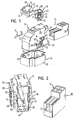
- the connector includes a first housing part 10, a second housing part 12, a Terminal element module 14, an actuator 16 and two spring elements 18, formed in this embodiment as leaf springs are.
- the first housing part 10 has a cuboid basic shape and is formed symmetrically with respect to a longitudinal center plane.
- a front End face 20 is at least partially formed as a curved surface.
- the first housing part 10 is open, Thus, the connection element module 14 inserted into the first housing part 10 can be.
- each having a detent opening 28 serve to receive at the connection element module 14 corresponding locking projections provided 30. Is the terminal element module 14 completely in the first one Housing part 10 is inserted, so snap the locking projections 30 of the terminal module 14 in the latching openings 28 of the side walls 26 such in that the connection element module 14 locks in the housing part 10 is.
- a locking tongue 32 arranged in the insertion direction of the terminal module 14 and essentially the entire length of the first Housing part 10 extends.
- a rail-like guide 34 is provided, in which the locking tongue 32 engages when the Anschlußmaschinemodul14 in the first housing part 10 is introduced.
- the locking tongue 32 a correct orientation of the terminal module 14 in the first Housing part 10 safe.
- the locking tongue 32 forms a secondary latch for located in the terminal module 14, not shown electrical Raelememte.
- Fig. 1 further shows that in a central region of each side wall 26th a cylindrical bearing journal 36 is provided which is perpendicular to the Side wall 26 extends to the outside.
- the bearing pins 36 serve for Storage of the actuator 16 on the first housing part 10. They are aligned with each other and form a pivot axis for the actuator 16th
- the actuator 16 is one formed by the through the bearing pin 36 Pivot axis pivoting lever, the first housing part 10 U-shaped clutching.
- the legs 38 of the actuator extend in Substantially parallel to the side walls 26 of the first housing part 10.
- In the area of the free leg ends 40 are circular openings 42 provided, in which the bearing pin 36 for holding the actuator 16 engage the housing part 10.
- the base 44 of the U-shaped Actuator 16 extends over the front end side 20th of the first housing part 10.
- the curvature of the front end 20 allows pivoting the actuator 16 over an angular range of about 90 °.
- the Actuator 16 is between an unlocking position in which the Leg 38 of the actuator 16 approximately parallel to a bottom 48 of the first housing part 10 are oriented, and a locking position pivotable, in which the legs 38 of the actuating member 16th are oriented approximately parallel to the rear end face 22.
- each leg 38 of the actuator 16 In the region of the free end 40 of each leg 38 of the actuator 16 is an outwardly facing circular arc segment-shaped guide slot 46 provided. One end 50 of the guide slot 46 is open. is the actuator 16 in its unlocked position, so has the open end 50 of the guide slot 46 in the direction of the bottom 48th of the first housing part 10.
- a bearing structure 56 is provided for the storage of a spring element 18, in conjunction is explained in more detail with Fig. 5.
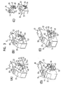
- the legs 38 of the actuator 16 are spread and the actuator 16 is pushed onto the first housing part 10, that the bearing pin 36 of the first housing part 10 in the bearing openings 42 of the actuator 16 engage.
- the Leg 38 of the actuator 16 with the rear end 22 and with the bottom 48 of the first housing part 10 an angle of about 45 ° (FIGS. 3C and 3D).
- the actuator 16 is then in its unlocked position folded (Fig. 3E).
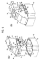
- the first housing part 10 with its underside 48 advances in the second housing part 12 inserted to an electrical connection between disposed in the terminal element module 14 electrical
- connecting elements and connecting elements which in the second housing part 12 are provided.
- guide pin 54 is arranged, which is extend into the interior of the second housing part 12.
- the guide pins 54 are arranged so that when mating the first and second housing part 10, 12 in the open ends 50 of the guide slots 46 of the actuator 16 engage.
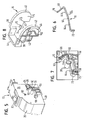
- each bearing structure 56 includes a front support projection 58 and a rear support projection 60. Above the rear support projection 60, the bearing structure 56 further includes a U-shaped spring bearing 62 which is open in the direction of the rear support projection 60.
- FIG. 6 shows a spring element 18 adapted to the bearing structure 56
- Spring element 18 is a leaf spring comprising a main portion 64, which consists of two sections 64a and 64b, which are easy to each other are angled.
- the kink between the sections 64a and 64b is designated by reference numeral 66 in FIG.
- a rear end portion closes 68 with respect to the portion 64b by more than 90 °, in Fig. 6 upwards, angled. In the area of the free end 70 of the rear End section 68 this is again angled in opposite directions.
- the front portion 64a goes into a front end portion 72nd about, with respect to the portion 64a by about 90 °, in Fig. 6 after below, angled.
- the spring member 18 is so in the bearing structure 56 inserted that the free end 70 of the rear end portion 68 engages in the U-shaped spring bearing 62, while the rear portion 64b of the main portion 64 on the rear support projection 60 and the front portion 64a on the front support portion 58 rests.
- the bearing pin 36 is located in the region of the kink 66 of the main portion 64 on the support projections 58, 60 opposite lying side of the spring element 18th
- the front end portion 72 forms the front end portion 72 with a front side 73 of the front support projection 58th an angle of about 10 ° to 20 °.
- the front end portions 72 of the spring elements 18 act at least at times with driving projections 74 of the actuator 16 together.
- the driving projections 74 are at the Inner sides 75 of the legs 38 of the actuator 16 are arranged.
- Each driving projection 74 has a shoulder on its rear side 76 on which the free end of the front end portion 72 of a Spring element 18 can support.
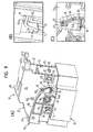
- Fig. 9A is the connector with mated housing parts 10, 12 and shown in the unlocked state.
- spring element 18 and driving projection 74th As an illustration the interaction of spring element 18 and driving projection 74th and the storage of the free end 70 of the spring element 18 in the Spring bearing 62 parts of the actuator 16 are broken away.
- the actuator 16 is in its unlocked position substantially parallel to the bottom 48 of the first Housing part 10 oriented.
- the front end portions are seated 72 of the spring elements 18 in this position of the actuating member 18 on the shoulder 76 of their respective driving projection 74 on.
- the spring elements 18 in the unlocked position of the Actuator 16 slightly biased.
- the rear end sections 68 extend the spring elements 18 each approximately parallel to a correspondingly shaped Rear wall 78 of the bearing structure 56.
- the free ends 70 of the rear End portions 68 each sit in their spring bearings 62nd
- the actuator 16 is made its unlocking position is moved to the locking position, i. worked up.
- 10A shows the connector in a half-locked state, in FIG the actuator 16 in an intermediate position of about 45 ° located. Again, portions of the actuator 60 are broken away, to the interaction of the spring elements 18 with their driving projections 74 and the course of the spring elements 18 in the area of their To illustrate spring bearing 62.
- the front end portion 72 is supported the spring elements 18 and in the intermediate position of the actuator 16 on the shoulder 76 of the driving projection 74 from.
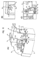
- a state of the connector is immediately before a complete Locking the housing parts 10, 12 shown. Also in Fig. 11A, parts of the actuator 16 have been broken away to take a look on the end portions 68, 72 of a spring element 18 to allow.
- the actuator 16 is located approximately in its locked position, i. almost perpendicular to the bottom 48 of the first housing part 10. In this position the base 44 of the actuator 16 directly above a on the Upper side of the first housing part provided latching hook 80, characterized is pressed into the housing part 10.
- the back End portions 68 form in this state with the rear sections 64b an angle of approximately 90 °. This is also the case rear end portions 68 with respect to the rear portions 64b maximum tension.
- Fig. 12A shows the connector in the fully locked state. Again, areas of the actuator 16 and the second housing part 12 broken away to take a look at the end sections 68, 72 of a To allow spring element 18.
- the legs 38 run of the actuator 16 is substantially perpendicular to the bottom 48 of the first housing part 10. In this position of the actuator 16 is the base 44 of the actuator 16 behind the latching hook 80, so that the actuator 16 by the latch hook 80 in the locking position is secured.
- the actuator is the 16th folded down again. Since the actuator 16 by the latch hook 80 is secured in the locked position, the latch hook 80 must be pressed into the first housing part 10 so that the base 44th of the actuator 16 are moved over the latch hook 80 away can (Fig. 13). When folding down the actuator 16 acts not together with the spring elements 18.
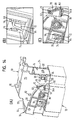
- Fig. 14 shows the connector in a state shortly before its complete Unlocking. To illustrate the end sections 68, 72 a spring element 18 are again areas of the actuator broken away.
- the legs 38 of the actuator 16 oriented approximately parallel to the underside of the first housing part 10. In this position of the actuator 16 are the driving projections 74 at the height of the front end portions 72 of Spring elements 18.
- the backs 84 of the shoulders 76 are the driving projections 74 slightly bevelled, so that the driving projections 74 when folding down the actuator 16 on the front end portions 72 of the spring elements 18 can accumulate.
- the front end portions 72 of the spring elements 18 are characterized in Direction of the main portions 64 of the spring elements 18 is pressed, in Fig. 14B to the right.
- the front end portions 72 act as small springs caused by the deflection by the driving lugs 74 are strained.
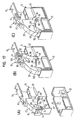
- Fig. 16 is a second embodiment of an inventive Connector shown. Components of this embodiment, the components similar to the first embodiment described above, are provided with the same reference numerals.
- the second embodiment of the connector shown in FIG. 16 differs from the first embodiment described above essentially in that only one spring element 86 is provided.
- This spring element 86 is mounted in the interior of the housing part 10 and acts through a in the front end 20 of the first housing part 10th provided recess 88 through with the actuator 16 together.
- the spring element 86 has a substantially straight main section 90 on, at an approximately rectangular, in Fig. 16A down bent, front end portion 92 connects.
- a rear end section 94 of the spring element 86 is U-shaped, wherein the base 95 of the rear end portion 94 in the same direction as the front end portion 92.
- the spring element 86 is mounted in a spring bearing 96 (FIG. 17), which is arranged in the interior of the first housing part 10.
- the spring bearing 96 has a matched to the main portion 90 of the spring member 86 Bearing ramp 98, at the rear end, a recess 100 for Receiving the U-shaped rear end portion 94 of the spring element 86 is located and the front 102 falls obliquely.
- Fig. 17A shows the connector in the unlocked state.
- this Condition is the main portion 90 of the spring member 86 at the bearing ramp 98, and the front end portion 92 of the spring member 86 is seated on the shoulder 76 of a driving projection 74 of the actuator 16 on.
- Fig. 17B shows a situation in which the actuator 16 directly located in front of its locking position. In this position of the actuator 16 is the base 44 of the actuator 16 via two the housing top arranged latching hook 80 and pushes them in the interior of the first housing part 10.
- the spring element 86 is maximum deformed. Not only is the main portion 90 of the spring element 86 curved backwards, but also the U-shaped rear end portion 94 compressed.
- Fig. 18 is a third embodiment of an inventive Connector shown. Again, components are those of the first Embodiment correspond, designated by the same reference numerals.
- the connector according to the third embodiment two spiral spring-like spring elements 104 instead of leaf springs on.
- the spring elements 104 are on both Provided sides of the first housing part 10 and surround the journals 36.
- a spring bearing 106 for receiving and Fixation of an angled inner end portion 108 of a coil spring 104 provided.
- the coil spring 104 goes outside in a straight portion 110 extending along the side wall 26 of the first housing part 10 extends forward and in one, in the Drawing down, angled outer end portion 112 passes.
- the straight portion 110 of the coil spring 104 is in FIG relaxed state of the coil spring 104, i. in the locked position of the actuating member 16, on a front support projection 58th on.
- the outer end portion 112 forms with a front side 73rd the front support projection 58 an angle of about 10 ° to 20 °. This is when folding down the actuator 16 from the Locking position in the unlocked position a deflection of the angled outer end portion 112 allows the spring element 104 after unlocking the connector again with the Actuator 16 to engage, as already in connection with Fig. 14 has been explained.
- the embodiments described above are either only leaf spring-like or only spiral spring-like spring elements 18, 86, 104. However, it is also possible, different spring elements in one Combine connectors. So can a connector with two outer spring elements which either leaf-spring-like spring elements 18 or helical spring-like spring elements 104 may be, in addition with a lying inside the first housing part 10 spring element be equipped.
- the internal spring element can while also either a helical spring-like spring element or a be leaf spring-like element 86.
- the above-described spring elements 18, 86, 104 are further all designed so that they are tensioned when locking the connector become. In other words, the actuator 16 only then works against the restoring force of the spring elements 18, 86 104 when it is out the unlocking position is moved to the locking position.
- the outer spring elements can be designed in this way be that they are cocked when locking the connector be and when unlocking with the actuator disengaged stand while an internal spring element tensioned when unlocking is and when locking with the actuator disengaged stands, or vice versa.
Landscapes
- Details Of Connecting Devices For Male And Female Coupling (AREA)
Abstract
Description
Es zeigen:
- Fig. 1
- eine Explosionsdarstellung des erfindungsgemäßen Steckverbinders gemäß einer ersten Ausführungsform;
- Fig. 2
- eine perspektivische Ansicht eines ersten Gehäuseteils und eines in das erste Gehäuseteil einsetzbaren Anschlusselementemoduls des Steckverbinders von Fig. 1;
- Fig. 3 A-E
- eine Abfolge von Schritten zur Montage von Betätigungsorgan und Federelementen an dem ersten Gehäuseteil des Steckverbinders von Fig. 1;
- Fig. 4 A,B
- eine perspektivische Ansicht des ersten und zweiten Gehäuseteils des Steckverbinders von Fig. 1, (A) in einem Vormontagezustand und (B) in einem zusammengesetzten und verriegelten Zustand;
- Fig. 5
- eine perspektivische Ansicht des ersten Gehäuseteils des Steckverbinders von Fig. 1;
- Fig. 6
- eine perspektivische Ansicht eines Federelements des Steckverbinders von Fig. 1;
- Fig. 7
- die Lagerung des Federelements von Fig. 6 an dem ersten Gehäuseteil des Steckverbinders von Fig. 1;
- Fig. 8
- eine perspektivische Ansicht des Betätigungsorgans des Steckverbinders von Fig. 1;
- Fig. 9 A-C
- eine perspektivische Ansicht (A) des Steckverbinders von Fig. 1 im zusammengesetzten und entriegelten Zustand und Detailansichten (B) des einen Endes und (C) des anderen Endes des Federelements;
- Fig. 10 A-C
- eine perspektivische Ansicht (A) des Steckverbinders von Fig. 1 im zusammengesetzten und halbverriegelten Zustand und Detailansichten (B) des einen Endes und (C) des anderen Endes eines Federelements;
- Fig. 11 A-C
- eine perspektivische Ansicht (A) des Steckverbinders von Fig. 1 im zusammengesetzten und verriegelten Zustand und Detailansichten (B) des einen Endes und (C) des anderen Endes eines Federelements;
- Fig. 12 A-C
- eine perspektivische Ansicht (A) des Steckverbinders von Fig. 1 im vollständig verriegelten Zustand und Detailansichten (B) des einen Endes und (C) des anderen Endes eines Federelements;
- Fig. 13 A,B
- eine perspektivische Ansicht (A) des verriegelten Steckverbinders von Fig. 12 kurz vor seiner Entriegelung und eine Detailansicht (B) der Oberseite des ersten Gehäuseteils;
- Fig. 14 A-C
- eine perspektivische Ansicht (A) des Steckverbinders von Fig. 13 unmittelbar vor seiner vollständigen Entriegelung und Detailansichten (B) des einen Endes und (C) des anderen Endes eines Federelements;
- Fig. 15 A-C
- (A) eine perspektivische Ansicht des Steckverbinders von Fig. 14 im vollständig entriegelten Zustand und Detailansichten (B) des einen Endes und (C) des anderen Endes eines Federelements;
- Fig. 16
- eine Explosionsansicht eines erfindungsgemäßen Steckverbinders gemäß einer zweiten Ausführungsform;
- Fig. 17 A-C
- Innenansichten des Steckverbinders von Fig. 16, (A) im entriegelten, (B) unmittelbar vor dem verriegelten und (C) im verriegelten Zustand;
- Fig. 18
- eine Explosionsansicht eines erfindungsgemäßen Steckverbinders gemäß einer dritten Ausführungsform;
- Fig. 19
- ein Federelement des Steckverbinders von Fig. 18; und
- Fig. 20
- die Lagerung des Federelements von Fig. 19 an einem Gehäuseteil des Steckverbinders von Fig. 18.
- 10
- erstes Gehäuseteil
- 12
- zweites Gehäuseteil
- 14
- Anschlusselementemodul
- 16
- Betätigungsorgan
- 18
- Federelement
- 20
- vordere Stirnseite
- 22
- hintere Stirnseite
- 24
- Rastzunge
- 26
- Seitenwand
- 28
- Rastöffnung
- 30
- Rastvorsprung
- 32
- Verriegelungszunge
- 34
- schienenartige Führung
- 36
- Lagerzapfen
- 38
- Schenkel
- 40
- Schenkelende
- 42
- Lageröffnung
- 44
- Basis
- 46
- Führungskulisse
- 48
- Unterseite
- 50
- offenes Ende
- 52
- Seitenwand
- 54
- Führungszapfen
- 56
- Lagerstruktur
- 58
- vorderer Auflagevorsprung
- 60
- hinterer Auflagevorsprung
- 62
- Federlager
- 64
- Hauptabschnitt
- 64a
- vorderer Teilabschnitt
- 64b
- hinterer Teilabschnitt
- 66
- Knickstelle
- 68
- hinterer Endabschnitt
- 70
- freies Ende
- 72
- vorderer Endabschnitt
- 73
- Vorderseite
- 74
- Mitnahmevorsprung
- 75
- Schenkelinnenseite
- 76
- Schulter
- 78
- Rückwand
- 80
- Rasthaken
- 82
- Ausrückvorsprung
- 84
- Rückseite
- 86
- Federelement
- 88
- Aussparung
- 90
- Hauptabschnitt
- 92
- vorderer Endabschnitt
- 94
- hinterer Endabschnitt
- 95
- Basis
- 96
- Federlager
- 98
- Lagerrampe
- 100
- Vertiefung
- 102
- Vorderseite
- 104
- Federelement
- 106
- Federlager
- 108
- innerer Endabschnitt
- 110
- gerader Abschnitt
- 112
- äußerer Endabschnitt
Claims (12)
- Elektrischer Steckverbinder mit zwei zusammensteckbaren und im zusammengesteckten Zustand verriegelbaren Gehäuseteilen (10, 12), die jeweils komplementär ausgebildete elektrische Anschlusselemente aufweisen, mit einem Betätigungsorgan (16) das zum Verriegeln oder Entriegeln der Gehäuseteile (10, 12) zwischen einer Entriegelungsstellung und einer Verriegelungsstellung bewegbar ist, und mit wenigstens einem Federelement (18; 86; 104), entgegen dessen Rückstellkraft das Betätigungsorgan (16) beim Verriegeln und/oder Entriegeln der Gehäuseteile (10, 12) zumindest zeitweise bewegbar ist.
- Steckverbinder nach Anspruch 1,
dadurch gekennzeichnet , dass das Federelement (18; 86; 104) mit dem Betätigungsorgan (16) zusammenwirkt, um das Betätigungsorgan (16) aus einer zwischen der Entriegelungsstellung und der Verriegelungsstellung gelegenen Zwischenstellung in die Entriegelungsstellung zu bewegen. - Steckverbinder nach Anspruch 1 oder 2,
dadurch gekennzeichnet , dass das oder ein weiteres Federelement mit dem Betätigungsorgan (16) zusammenwirkt, um das Betätigungsorgan (16) aus einer zwischen der Entriegelungsstellung und der Verriegelungsstellung gelegenen Zwischenstellung in die Verriegelungsstellung zu bewegen. - Steckverbinder nach einem der vorherigen Ansprüche,
dadurch gekennzeichnet , dass das Federelement (18; 86; 104) oder die Federelemente (18; 86; 104) und das Betätigungsorgan (16) in der Verriegelungsstellung und/oder Entriegelungsstellung des Betätigungsorgans (16), insbesondere durch einen Ausrückvorsprung (82), außer Eingriff bringbar sind. - Steckverbinder nach einem der vorherigen Ansprüche,
dadurch gekennzeichnet , dass zwei, insbesondere auf gegenüberliegenden Seiten des einen Gehäuseteils (10) angeordnete, Federelemente (18; 104) vorgesehen sind. - Steckverbinder nach Anspruch 5,
dadurch gekennzeichnet , dass die Federelemente (18; 104) jeweils zwischen dem Betätigungsorgan (16) und einer Seitenwand (26) des einen Gehäuseteils (10) angeordnet sind. - Steckverbinder nach einem der vorherigen Ansprüche,
dadurch gekennzeichnet , dass ein Federelement (86) vorgesehen ist, welches zumindest bereichsweise im Inneren des einen Gehäuseteils (10) angeordnet ist und insbesondere durch eine Aussparung (88) in einer Stirnseite (20) des Gehäuseteils (10) mit dem Betätigungsorgan (16) zusammenwirkt. - Steckverbinder nach einem der vorherigen Ansprüche,
dadurch gekennzeichnet , dass ein erstes Ende (70; 94; 108) des wenigstens einen Federelements (18; 86; 104) in einem Federlager (62; 100; 106) des einen Gehäuseteils (10) gelagert ist. - Steckverbinder nach einem der vorherigen Ansprüche,
dadurch gekennzeichnet , dass das Betätigungsorgan (16) ein Mitnahmemittel, insbesondere einen Mitnahmevorsprung (74), aufweist, um ein zweites Ende (72; 92; 112) des Federelements (18; 86; 104) beim Bewegen des Betätigungsorgans (16) auszulenken. - Steckverbinder nach einem der vorherigen Ansprüche,
dadurch gekennzeichnet , dass wenigstens ein Federelement (18; 86) eine Blattfeder ist, welches insbesondere einen im Wesentlichen geraden Hauptabschnitt (64; 90) und zwei sich daran anschließende Endabschnitte (68, 72; 92, 94) aufweist, die, insbesondere in entgegengesetzte Richtungen, bezüglich des Hauptabschnitts (64; 90) abgewinkelt sind. - Steckverbinder nach einem der vorherigen Ansprüche,
dadurch gekennzeichnet , dass wenigstens ein Federelement (104) eine Spiralfeder ist, welches insbesondere eine Schwenkachse des Betätigungsorgans (16) umgibt. - Steckverbinder nach einem der vorherigen Ansprüche,
dadurch gekennzeichnet , dass die Gehäuseteile (10, 12), insbesondere bei einer Bewegung des Betätigungsorgans (16) aus der Entriegelungsstellung in die Verriegelungsstellung, durch das Betätigungsorgan (16) zusammenziehbar sind.
Applications Claiming Priority (2)
| Application Number | Priority Date | Filing Date | Title |
|---|---|---|---|
| GB0408185 | 2004-04-13 | ||
| GBGB0408185.7A GB0408185D0 (en) | 2004-04-13 | 2004-04-13 | Electrical connector |
Publications (2)
| Publication Number | Publication Date |
|---|---|
| EP1587179A1 true EP1587179A1 (de) | 2005-10-19 |
| EP1587179B1 EP1587179B1 (de) | 2006-08-30 |
Family
ID=32320719
Family Applications (1)
| Application Number | Title | Priority Date | Filing Date |
|---|---|---|---|
| EP04021748A Expired - Lifetime EP1587179B1 (de) | 2004-04-13 | 2004-09-13 | Elektrischer Steckverbinder |
Country Status (4)
| Country | Link |
|---|---|
| EP (1) | EP1587179B1 (de) |
| AT (1) | ATE338359T1 (de) |
| DE (1) | DE502004001340D1 (de) |
| GB (1) | GB0408185D0 (de) |
Cited By (1)
| Publication number | Priority date | Publication date | Assignee | Title |
|---|---|---|---|---|
| EP1850423A1 (de) * | 2006-04-26 | 2007-10-31 | Alcatel Lucent | System zur Entkopplung eines Steckerpaares |
Citations (2)
| Publication number | Priority date | Publication date | Assignee | Title |
|---|---|---|---|---|
| US5482394A (en) * | 1993-03-17 | 1996-01-09 | Yazaki Corporation | Connector equipped with fitting lever and method of mounting winding spring in it |
| US5484297A (en) * | 1993-09-27 | 1996-01-16 | Yazaki Corporation | Lever fitting-type connector |
-
2004
- 2004-04-13 GB GBGB0408185.7A patent/GB0408185D0/en not_active Ceased
- 2004-09-13 DE DE502004001340T patent/DE502004001340D1/de not_active Expired - Fee Related
- 2004-09-13 EP EP04021748A patent/EP1587179B1/de not_active Expired - Lifetime
- 2004-09-13 AT AT04021748T patent/ATE338359T1/de not_active IP Right Cessation
Patent Citations (2)
| Publication number | Priority date | Publication date | Assignee | Title |
|---|---|---|---|---|
| US5482394A (en) * | 1993-03-17 | 1996-01-09 | Yazaki Corporation | Connector equipped with fitting lever and method of mounting winding spring in it |
| US5484297A (en) * | 1993-09-27 | 1996-01-16 | Yazaki Corporation | Lever fitting-type connector |
Cited By (1)
| Publication number | Priority date | Publication date | Assignee | Title |
|---|---|---|---|---|
| EP1850423A1 (de) * | 2006-04-26 | 2007-10-31 | Alcatel Lucent | System zur Entkopplung eines Steckerpaares |
Also Published As
| Publication number | Publication date |
|---|---|
| GB0408185D0 (en) | 2004-05-19 |
| DE502004001340D1 (de) | 2006-10-12 |
| ATE338359T1 (de) | 2006-09-15 |
| EP1587179B1 (de) | 2006-08-30 |
Similar Documents
| Publication | Publication Date | Title |
|---|---|---|
| DE69907832T2 (de) | Elektrischer Verbinder mit Lagesicherungsvorrichtung | |
| EP0899818B1 (de) | Elektrische Anschlussklemme, insbesondere für den Einsatz auf Leiterplatten | |
| DE69410009T2 (de) | Elektrischer Steckverbinder | |
| EP2253260B1 (de) | Steckbares Rohrsystem für einen Staubsauger | |
| DE19727478A1 (de) | Buchsenartige elektrische Kontaktanordnung | |
| DE4239124A1 (de) | ||
| EP0417353B1 (de) | Elektrische Kontaktsteckvorrichtung | |
| DE19714459C2 (de) | Steckverbinder mit einer Gehäuseverriegelung | |
| DE19920511A1 (de) | Türinnengriff für Automobile | |
| WO1997009752A1 (de) | Elektrischer verbinder mit kontaktsicherungsschieber | |
| DE10110092C1 (de) | Steckverbinder mit einer Gehäuseverriegelung | |
| EP0984524B1 (de) | Zweiteiliger elektrischer Steckverbinder mit einem Koppelteil und einem bewegbaren Kontrollelement | |
| DE10159197B4 (de) | Verbinder und Verfahren zum Zusammenbauen eines Verbinders | |
| DE102008050477A1 (de) | Kochgeschirr mit abnehmbarem Griff- oder Stielelement | |
| DE102017124670A1 (de) | Elektrische Steckverbindung | |
| DE60034626T2 (de) | Verbinder mit Verhinderung einer unvollständigen Kupplung | |
| EP3785335A1 (de) | Steckverbinderteil einer steckverbindung | |
| EP3679633A1 (de) | Einzugshilfe von elektrischen steckverbindern mit verschieberichtung in steckrichtung | |
| EP1587179B1 (de) | Elektrischer Steckverbinder | |
| EP1411596B1 (de) | Stecker mit Halteelement | |
| DE102017203909A1 (de) | Elektrische Steckverbindungen mit lösbarer Verriegelung | |
| DE8620558U1 (de) | Trennschied für Organisationsschublade | |
| EP1526616B1 (de) | Elektrischer Steckverbinder | |
| EP1679767A1 (de) | Elektrischer Steckverbinder | |
| DE1500840A1 (de) | Mechanische Kupplung |
Legal Events
| Date | Code | Title | Description |
|---|---|---|---|
| PUAI | Public reference made under article 153(3) epc to a published international application that has entered the european phase |
Free format text: ORIGINAL CODE: 0009012 |
|
| 17P | Request for examination filed |
Effective date: 20050316 |
|
| AK | Designated contracting states |
Kind code of ref document: A1 Designated state(s): AT BE BG CH CY CZ DE DK EE ES FI FR GB GR HU IE IT LI LU MC NL PL PT RO SE SI SK TR |
|
| AX | Request for extension of the european patent |
Extension state: AL HR LT LV MK |
|
| GRAP | Despatch of communication of intention to grant a patent |
Free format text: ORIGINAL CODE: EPIDOSNIGR1 |
|
| RTI1 | Title (correction) |
Free format text: ELECTRICAL CONNECTOR |
|
| GRAS | Grant fee paid |
Free format text: ORIGINAL CODE: EPIDOSNIGR3 |
|
| AKX | Designation fees paid |
Designated state(s): AT BE BG CH CY CZ DE DK EE ES FI FR GB GR HU IE IT LI LU MC NL PL PT RO SE SI SK TR |
|
| GRAA | (expected) grant |
Free format text: ORIGINAL CODE: 0009210 |
|
| AK | Designated contracting states |
Kind code of ref document: B1 Designated state(s): AT BE BG CH CY CZ DE DK EE ES FI FR GB GR HU IE IT LI LU MC NL PL PT RO SE SI SK TR |
|
| PG25 | Lapsed in a contracting state [announced via postgrant information from national office to epo] |
Ref country code: IE Free format text: LAPSE BECAUSE OF FAILURE TO SUBMIT A TRANSLATION OF THE DESCRIPTION OR TO PAY THE FEE WITHIN THE PRESCRIBED TIME-LIMIT Effective date: 20060830 Ref country code: SK Free format text: LAPSE BECAUSE OF FAILURE TO SUBMIT A TRANSLATION OF THE DESCRIPTION OR TO PAY THE FEE WITHIN THE PRESCRIBED TIME-LIMIT Effective date: 20060830 Ref country code: NL Free format text: LAPSE BECAUSE OF FAILURE TO SUBMIT A TRANSLATION OF THE DESCRIPTION OR TO PAY THE FEE WITHIN THE PRESCRIBED TIME-LIMIT Effective date: 20060830 Ref country code: SI Free format text: LAPSE BECAUSE OF FAILURE TO SUBMIT A TRANSLATION OF THE DESCRIPTION OR TO PAY THE FEE WITHIN THE PRESCRIBED TIME-LIMIT Effective date: 20060830 Ref country code: PL Free format text: LAPSE BECAUSE OF FAILURE TO SUBMIT A TRANSLATION OF THE DESCRIPTION OR TO PAY THE FEE WITHIN THE PRESCRIBED TIME-LIMIT Effective date: 20060830 Ref country code: FI Free format text: LAPSE BECAUSE OF FAILURE TO SUBMIT A TRANSLATION OF THE DESCRIPTION OR TO PAY THE FEE WITHIN THE PRESCRIBED TIME-LIMIT Effective date: 20060830 Ref country code: GB Free format text: LAPSE BECAUSE OF FAILURE TO SUBMIT A TRANSLATION OF THE DESCRIPTION OR TO PAY THE FEE WITHIN THE PRESCRIBED TIME-LIMIT Effective date: 20060830 Ref country code: RO Free format text: LAPSE BECAUSE OF FAILURE TO SUBMIT A TRANSLATION OF THE DESCRIPTION OR TO PAY THE FEE WITHIN THE PRESCRIBED TIME-LIMIT Effective date: 20060830 Ref country code: CZ Free format text: LAPSE BECAUSE OF FAILURE TO SUBMIT A TRANSLATION OF THE DESCRIPTION OR TO PAY THE FEE WITHIN THE PRESCRIBED TIME-LIMIT Effective date: 20060830 |
|
| REG | Reference to a national code |
Ref country code: GB Ref legal event code: FG4D Free format text: NOT ENGLISH |
|
| PGFP | Annual fee paid to national office [announced via postgrant information from national office to epo] |
Ref country code: DE Payment date: 20060907 Year of fee payment: 3 |
|
| PGFP | Annual fee paid to national office [announced via postgrant information from national office to epo] |
Ref country code: FR Payment date: 20060908 Year of fee payment: 3 |
|
| REG | Reference to a national code |
Ref country code: CH Ref legal event code: EP |
|
| PG25 | Lapsed in a contracting state [announced via postgrant information from national office to epo] |
Ref country code: BE Free format text: LAPSE BECAUSE OF NON-PAYMENT OF DUE FEES Effective date: 20060930 Ref country code: MC Free format text: LAPSE BECAUSE OF NON-PAYMENT OF DUE FEES Effective date: 20060930 |
|
| REG | Reference to a national code |
Ref country code: IE Ref legal event code: FG4D Free format text: LANGUAGE OF EP DOCUMENT: GERMAN |
|
| REF | Corresponds to: |
Ref document number: 502004001340 Country of ref document: DE Date of ref document: 20061012 Kind code of ref document: P |
|
| PG25 | Lapsed in a contracting state [announced via postgrant information from national office to epo] |
Ref country code: BG Free format text: LAPSE BECAUSE OF FAILURE TO SUBMIT A TRANSLATION OF THE DESCRIPTION OR TO PAY THE FEE WITHIN THE PRESCRIBED TIME-LIMIT Effective date: 20061130 Ref country code: SE Free format text: LAPSE BECAUSE OF FAILURE TO SUBMIT A TRANSLATION OF THE DESCRIPTION OR TO PAY THE FEE WITHIN THE PRESCRIBED TIME-LIMIT Effective date: 20061130 Ref country code: DK Free format text: LAPSE BECAUSE OF FAILURE TO SUBMIT A TRANSLATION OF THE DESCRIPTION OR TO PAY THE FEE WITHIN THE PRESCRIBED TIME-LIMIT Effective date: 20061130 |
|
| PG25 | Lapsed in a contracting state [announced via postgrant information from national office to epo] |
Ref country code: ES Free format text: LAPSE BECAUSE OF FAILURE TO SUBMIT A TRANSLATION OF THE DESCRIPTION OR TO PAY THE FEE WITHIN THE PRESCRIBED TIME-LIMIT Effective date: 20061211 |
|
| PG25 | Lapsed in a contracting state [announced via postgrant information from national office to epo] |
Ref country code: PT Free format text: LAPSE BECAUSE OF FAILURE TO SUBMIT A TRANSLATION OF THE DESCRIPTION OR TO PAY THE FEE WITHIN THE PRESCRIBED TIME-LIMIT Effective date: 20070206 |
|
| ET | Fr: translation filed | ||
| NLV1 | Nl: lapsed or annulled due to failure to fulfill the requirements of art. 29p and 29m of the patents act | ||
| GBV | Gb: ep patent (uk) treated as always having been void in accordance with gb section 77(7)/1977 [no translation filed] |
Effective date: 20060830 |
|
| REG | Reference to a national code |
Ref country code: IE Ref legal event code: FD4D |
|
| PLBE | No opposition filed within time limit |
Free format text: ORIGINAL CODE: 0009261 |
|
| STAA | Information on the status of an ep patent application or granted ep patent |
Free format text: STATUS: NO OPPOSITION FILED WITHIN TIME LIMIT |
|
| 26N | No opposition filed |
Effective date: 20070531 |
|
| PG25 | Lapsed in a contracting state [announced via postgrant information from national office to epo] |
Ref country code: AT Free format text: LAPSE BECAUSE OF NON-PAYMENT OF DUE FEES Effective date: 20060913 |
|
| BERE | Be: lapsed |
Owner name: DELPHI TECHNOLOGIES, INC. Effective date: 20060930 |
|
| PG25 | Lapsed in a contracting state [announced via postgrant information from national office to epo] |
Ref country code: GR Free format text: LAPSE BECAUSE OF FAILURE TO SUBMIT A TRANSLATION OF THE DESCRIPTION OR TO PAY THE FEE WITHIN THE PRESCRIBED TIME-LIMIT Effective date: 20061201 |
|
| PG25 | Lapsed in a contracting state [announced via postgrant information from national office to epo] |
Ref country code: EE Free format text: LAPSE BECAUSE OF FAILURE TO SUBMIT A TRANSLATION OF THE DESCRIPTION OR TO PAY THE FEE WITHIN THE PRESCRIBED TIME-LIMIT Effective date: 20060830 |
|
| PG25 | Lapsed in a contracting state [announced via postgrant information from national office to epo] |
Ref country code: TR Free format text: LAPSE BECAUSE OF FAILURE TO SUBMIT A TRANSLATION OF THE DESCRIPTION OR TO PAY THE FEE WITHIN THE PRESCRIBED TIME-LIMIT Effective date: 20060830 Ref country code: LU Free format text: LAPSE BECAUSE OF NON-PAYMENT OF DUE FEES Effective date: 20060913 Ref country code: DE Free format text: LAPSE BECAUSE OF NON-PAYMENT OF DUE FEES Effective date: 20080401 Ref country code: HU Free format text: LAPSE BECAUSE OF FAILURE TO SUBMIT A TRANSLATION OF THE DESCRIPTION OR TO PAY THE FEE WITHIN THE PRESCRIBED TIME-LIMIT Effective date: 20070301 |
|
| REG | Reference to a national code |
Ref country code: FR Ref legal event code: ST Effective date: 20080531 |
|
| PG25 | Lapsed in a contracting state [announced via postgrant information from national office to epo] |
Ref country code: FR Free format text: LAPSE BECAUSE OF NON-PAYMENT OF DUE FEES Effective date: 20071001 |
|
| PG25 | Lapsed in a contracting state [announced via postgrant information from national office to epo] |
Ref country code: CY Free format text: LAPSE BECAUSE OF FAILURE TO SUBMIT A TRANSLATION OF THE DESCRIPTION OR TO PAY THE FEE WITHIN THE PRESCRIBED TIME-LIMIT Effective date: 20060830 |
|
| REG | Reference to a national code |
Ref country code: CH Ref legal event code: PL |
|
| PG25 | Lapsed in a contracting state [announced via postgrant information from national office to epo] |
Ref country code: CH Free format text: LAPSE BECAUSE OF NON-PAYMENT OF DUE FEES Effective date: 20060930 Ref country code: LI Free format text: LAPSE BECAUSE OF NON-PAYMENT OF DUE FEES Effective date: 20060930 |
|
| PG25 | Lapsed in a contracting state [announced via postgrant information from national office to epo] |
Ref country code: IT Free format text: LAPSE BECAUSE OF NON-PAYMENT OF DUE FEES Effective date: 20080913 |
|
| PG25 | Lapsed in a contracting state [announced via postgrant information from national office to epo] |
Ref country code: CH Free format text: LAPSE BECAUSE OF NON-PAYMENT OF DUE FEES Effective date: 20080930 Ref country code: LI Free format text: LAPSE BECAUSE OF NON-PAYMENT OF DUE FEES Effective date: 20080930 |
|
| PGFP | Annual fee paid to national office [announced via postgrant information from national office to epo] |
Ref country code: IT Payment date: 20070930 Year of fee payment: 4 |