EP1586873A1 - Cartouche de détection de niveau de liquide dans un réservoir hydraulique, réservoir hydraulique et procédé de montage de la cartouche - Google Patents
Cartouche de détection de niveau de liquide dans un réservoir hydraulique, réservoir hydraulique et procédé de montage de la cartouche Download PDFInfo
- Publication number
- EP1586873A1 EP1586873A1 EP05007172A EP05007172A EP1586873A1 EP 1586873 A1 EP1586873 A1 EP 1586873A1 EP 05007172 A EP05007172 A EP 05007172A EP 05007172 A EP05007172 A EP 05007172A EP 1586873 A1 EP1586873 A1 EP 1586873A1
- Authority
- EP
- European Patent Office
- Prior art keywords
- skirt
- housing
- cartridge
- base
- stop
- Prior art date
- Legal status (The legal status is an assumption and is not a legal conclusion. Google has not performed a legal analysis and makes no representation as to the accuracy of the status listed.)
- Granted
Links
Images


Classifications
-
- G—PHYSICS
- G01—MEASURING; TESTING
- G01F—MEASURING VOLUME, VOLUME FLOW, MASS FLOW OR LIQUID LEVEL; METERING BY VOLUME
- G01F23/00—Indicating or measuring liquid level or level of fluent solid material, e.g. indicating in terms of volume or indicating by means of an alarm
- G01F23/30—Indicating or measuring liquid level or level of fluent solid material, e.g. indicating in terms of volume or indicating by means of an alarm by floats
Definitions
- the invention relates to a level detection cartridge of liquid in a hydraulic tank of a motor vehicle. More precisely, the invention relates to means for maintaining the cartridge in a specific housing in the tank. The invention also relates to a method for mounting such a device cartridge in said housing. The invention also relates to a hydraulic tank provided with such a cartridge.
- An object of the invention is to allow a good maintenance of a detection cartridge in a housing in a tank hydraulic. Another object of the invention is to facilitate a mounting of the cartridge in the slot, without the risk of damaging the cartridge during assembly or disassembly. A further object of the invention is to increase a precision of the detection of the liquid level in the tank by the cartridge.
- a motor vehicle has several hydraulic tanks, like a brake fluid reservoir and a fuel tank. At a operation of the vehicle, a quantity of liquid in these tanks tends to to decrease. For example, a quantity of brake fluid may decrease in the brake fluid reservoir due to a hydraulic leak at the location of a brake system or tank itself.
- the legislation requires manufacturers to provide means to inform a driver when that the level of liquid in the reservoir is below a threshold level previously fixed.
- a light is on a board vehicle when the fluid level exceeds this defined threshold as critical.
- the lighting of the indicator light is for example controlled by an electrical circuit arranged at the location of the tank.
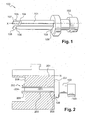
- a cartridge 100 for detecting a liquid level in a tank includes, for example, an electrical circuit provided with a flexible blade switch (ILS).
- ILS flexible blade switch
- the cartridge 100 is disposed in a housing 202 formed in a reservoir 200.
- the housing 202 comprises a first part 203 having an inner contour following an outer contour of a skirt 101 of the cartridge 100.
- the first part 203 of the housing 202 opens by an outer end 205 towards the outside of the tank 200, and by an internal end 206 in a second portion 204 of the housing 202.
- the cartridge 100 includes the skirt 101 and a connector 102.
- connector 102 is fixed by any means to a first end 103 of the 101.
- a second end 104 of the skirt 101 is provided with two tabs 105 and 106, extending parallel to an axis X of the skirt 101.
- free end of each of the legs 105 and 106 comprises a notch, respectively 107 and 108.
- the notches 107 and 108 extend perpendicular to the X axis, outwardly with respect to said X axis.
- This axial displacement can be at the origin of rattling which can inconvenience or disturb a driver.
- a quality of the detection of the level N of liquid 201 in the hydraulic reservoir 200 can be decreased due to a sloshing of the cartridge 100 in the housing 202.
- the notches 107 and 108 and therefore the legs 105 and 106 are constrained by the inner wall of the first portion 203 of the housing 202. This constraint can deform or weaken the legs 105 and 106. The quality the maintenance of the cartridge 100 can feel.
- the invention seeks to solve the problems described above, by proposing a very precise detection device for the level of liquid in a hydraulic tank.
- the principle of the invention is based on a holding device, forming stop, a cylindrical rod of the detection device against a rim internal support.
- the internal support flange is formed by a wall of the tank, describing a housing in the tank.
- the device detection is arranged in this housing.
- the stop is an integral part of the cylindrical rod.
- the abutment portion has an initial position allowing a easy introduction of the cylindrical rod into the housing. Once the stem cylinder inserted in the housing, the holding device is brought and stuck in a position such that it forms a rigid stop of the rod against the internal support edge of the housing.
- the holding device of the invention is for example provided with two arms. Each arm can fold outward only. Both arms are secured by one end of the cylindrical rod, and by another end of a base. Once the cylindrical rod introduced into the housing, the base is raised in the direction of the cylindrical rod. The arms fold outward, forming for example two rigid fins. We obtain a rigid internal stop.
- the cylindrical rod is provided with a second stop, opposite to the first.
- the second stop is for example formed by a housing, one of which dimension is greater than one dimension of the housing. So once the cylindrical rod introduced into the housing, the housing comes into outer abutment against a rim of external support.
- the outer support flange is formed by an outer wall of the tank bordering an inlet end of the housing.
- the cylindrical rod is held in the housing by both stops.
- the arms of the internal stop are folded so as to maintain the cylindrical rod in tension.
- the arms are in a folded state of restraint, and therefore tend to unfold.
- the outer stop is thus pulled against the rim external support. Any risk of play of the skirt in the house is eliminated.
- the materials used to form the cylindrical rod, the arms and the base are such that once folded the arms can no longer unfold completely. Thus, even if the base moves away more or less from the stem cylindrical, the arms remain at least partially bent outwards. The stop therefore always exists, thus ensuring a maintenance of the cylindrical rod in the accommodation.
- the base can be provided with a means for keep the base fixed on the cylindrical rod.
- the legs connect the base to the stem, a distance between the stem and the base that may vary according to a state of folding of the legs. When the legs are fully folded, the base comes into contact with the end of the rod carrying the legs.
- the way to maintain the base fixed on the rod, or means of attachment, is by example integral with the end of the rod carrying the legs. So, so that the base is fixed on the stem, it is necessary that the legs are fully folded.
- the means of fixing the base to the stem therefore allows to maintain the folded state of the legs.
- the fixing means is such that a solidarity is facilitated. A separation of the base and the stem cylindrical, it can be made difficult because of a particular form of fixing means.
- the invention also proposes a hydraulic reservoir provided with such detection device.
- the invention also proposes a method of mounting said device in the housing formed on the tank.
- the subject of the invention is therefore a cartridge for detecting the level of liquid in a reservoir, the cartridge being able to be housed in a partially through housing formed in the reservoir, the housing comprising two parts, a first part for receiving the cartridge. opening through an outer end to the outside of the tank and through an inner end into a second portion of the housing, the second portion of the housing forming a cavity, the cartridge having a skirt provided with a first stop at a first end, and a second abutment at a second end, the skirt being held in the cylindrical housing by means of the two abutments, characterized in that at least one end of the skirt is provided with foldable means forming a stop.
- the means foldable are provided with at least two hinges, one high end of each of the hinges being integral with one end of the skirt, a bottom end of each of the hinges being secured to a base, each hinge being provided with two parts, a junction between the two parts moving outwards as the base moves up towards the end of the skirt.
- Fixation can be performed in such a way as to be reversible or irreversible.
- the invention also relates to a hydraulic fluid reservoir equipped with a detection cartridge of the invention.
- a cartridge 300 can be seen according to an example of embodiment of the invention.
- the cartridge 300 has a skirt 301.
- the skirt 301 is provided at a first end 302 with a member 303 forming a first stop 303.
- the skirt 301 is provided at a second end 304 a second stop 305.
- the first stop 303 is formed by a housing.
- the second stop 305 is formed according to the invention by means foldable 306 and 307.
- the cartridge 300 is in the rest position.
- position rest means the position in which the collapsible means 306 and 307 are in an unconstrained state, ie unfolded.
- the cartridge 300 can be seen in a position constraint. That is, the collapsible means 306 and 307 are folded in order to to be able to form the second stop 305.
- the foldable means 306 and 307 consist of two hinges 306 and 307.
- Each hinge 306 or 307 is fixed on the one hand to a base 308 by a low end 309 or 310, and secondly at the second end 304 301 of the skirt by a high end 311 or 312.
- Each hinge 306 or 307 has two parts, respectively top part 313 or 314 and part 315 or 316.
- a junction 317 or 318 between the lower part 315 or 316 and the upper part 313 or 314 allows an outward separation of each of the hinges 306 and 307.
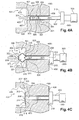
- FIG. 4 a three-step assembly (4A, 4B and 4C) can be seen of the cartridge 300 of the invention in a housing 401 formed in a 400 tank of hydraulic fluid.
- Housing 401 has two parts, respectively 403 and 404.
- Housing 401 is partially crossing. That is, the housing 401 passes through the tank 400 without all the way through it.
- Housing-401 has a first part 403 cylindrical.
- the first portion 403 of the housing 401 may have a section square, or rectangular.
- the first cylindrical portion 403 opens by an outer end 406 towards the outside of the tank 400, and by a internal end 407 in a second portion 404 of the housing 401.
- second part 404 is formed by a cavity 404 delimited by a wall 405 of the tank 400.
- the folding means 306 and 307 are in lying position. That is, the hinges 306 and 307 move away from their entire length the base 308 of the second end 304 of the skirt 301 carrying said hinges 306 and 307.
- the pedestal 308, the hinges 306 and 307 and the skirt 301 are introduced. in the cylindrical portion 403 of the housing 401 by the outer end 406 of the cylindrical housing 403.
- the upper part 313 or 314 of a hinge 306 or 307 hangs on a whole length inside the lower part 315 or 316 of the same hinge 306 or 307 ( Figure 4C). Junction 317 or 318 points to outside compared to an inner perimeter delimited by the two hinges 306 and 307.
- the base 308 is secured to the second end 304 of the skirt 301.
- the hinges 306 and 307 are folded then forming the second stop 305 of the cartridge 300.
- the cartridge 300 is housed in the housing 401 formed in the body of the tank 400, and is held in said housing 401 by its two stops 303 and 305.
- the second stop 305 it is possible to realize the second stop 305 so that a high end 320 or 321 of each of the hinges 306 and 307 is bevelled, so as to be able to marry an outer contour of the second end 304 of the skirt 301. From same, a low end 322 or 323 of each of the hinges 306 and 307 can be beveled so that it can conform to a contour of the base 308.
- the skirt 301 and the second stop 305 may be for example made of rigid polypropylene.
- the abutment 305 is then a rigid abutment. More generally, it is used to make the skirt 301 and the second stop 305 a compound such as when the base 308 moves away, so desired, the second end 304 of the skirt 301, the hinges 306 and 307 remain at least partially folded. So, the 300 cartridge is always kept in the dwelling 401 from which it can not accidentally withdraw.
- the fastening means 324 has a protuberance 325 located on an outer face 327 of the second end 304 of the skirt 301, and a port 326 formed on the base 308 ( Figure 4).
- Port 326 can be circular.
- the protrusion 325 has for example a round outer profile. By profile we mean, the profile of the protuberance in a plane that contains the direction of the protuberance. 325 round protrusion can snap in the hole 326 when the hinges 306 and 307 are completely folded.
- the protrusion 325 is such that snapping is easy but the dismounting difficult.
- protuberance 325 having a angular outer profile.
- the snapping of the protrusion 325, the outer profile is angular, in the hole 326 formed in the base 308 is easy, while disassembly compared to the base 308, it is impossible.
- a distance between the two stops 303 and 305 it is possible to providing adjustment means, on the fixing means, a distance between the two stops 303 and 305. For example, we are cleaning up the protrusion 325 or in the orifice 326 several detent notches. It is thus possible to adjust the distance separating the two stops 303 and 305 according to a length of the housing 401, to make up the manufacturing tolerances.
- the fixing means 324 of the base 308 on the skirt 301 makes it possible to keep the skirt 301 in traction against the inner wall 405 of the tank 400.
- the hinges 306 and 307 tend to unfold, which tends to pull and apply the face 319 of the housing 303 against the outer wall 408 of the tank 400.
- the skirt is thus trapped between its two stops 303 and 305 in the first portion 403 of the housing 401. All axial displacement of the skirt 301 in dwelling 401 is forbidden.
- the housing 401 it is possible to realize the housing 401 so as to what internal dimensions of the cylindrical portion 403 of the housing 401 follow outer dimensions of the skirt 301.
- an inner wall of the cylindrical portion 403 is in close contact with the skirt 301, preventing any radial movement of the skirt 301 in the housing 401.
- hinges 306 and 307. it is possible, in other embodiments, to vary the number of hinges 306 and 307. For example, one can realize a second stop 305 having three or four hinges.
- the detection cartridge 300 of the invention may for example have a connector housed in the housing 303 and an electrical circuit housed in the skirt 301 (not visible in the figures).
- the electrical circuit comprising for example a switch with flexible blades, is closed, allowing a warning light to be illuminated on a dashboard of the vehicle.
- the invention also relates to a tank 400 provided with such 300 cartridge for detecting the level of liquid.
- the invention also relates to a method for mounting a cartridge 300 in a housing 401 formed in a tank 400.
- the molding is made of so that the foldable means 306 and 307 are secured by a first end 315 or 316 of a second end 304 of the skirt 301, and by a second end 313 or 314 of a base 308.
- a first end 302 of the skirt 301 is secured to an element 303 forming a stop.
- the abutment member 303 is brought into abutment against a wall 408 tank 400, the second end 304 of the skirt 301 opening into a cavity-shaped portion 404 of the housing 401.
- the pedestal 308 is raised towards the second end 304 of the skirt 301, by folding the foldable means 306 and 307 to the outside.
- the foldable means 306 and 307 then form a stop 305 against a wall 405 of the tank 400 bordering an internal end 407 of the part cylindrical 403 of housing 401.
- the cavity 404 is opening towards the outside of the tank 400.
- the base 308 in the direction of the skirt 301.
- a string to raise the base 308 towards the skirt 301, it is possible to use a string.
- a second end of the string is free.
- a length of the string is greater than a total length of housing 401, so that the second end of the string is located out of the housing 401, side first stop 303, when the cartridge 300 is disposed in the housing 401.
- the second end of the string so as to pull the base towards the skirt 301, while maintaining the cartridge 300 in its housing 401, for example in applying the first stop 303 against the outer wall 408 of the reservoir 400.
- the hinges 306 and 307 are thus folded, the cartridge 300 can not no longer withdraw from dwelling 401.
- a length of the skirt 301 is substantially equal to a total length of the housing 401.
- length total housing 401 is meant length from the outer end 406 of the cylindrical portion 403 of the housing 401 to a bottom 409 of the cavity 404.
- bottom 409 of the cavity 404 is meant opposite end to the end bordering the inner end 407 of the cylindrical portion 403 of the housing 401.
- cartridge 300 at the location of the first stop 303, in one direction opposite to the direction of introduction of the cartridge 300 into the housing 401, to bring the hinges 306 and 307, folded, and the base 308 in abutment against the inner wall 405 of the cavity 404 bordering the inner end 407 of the cylindrical portion 403 of the housing 401. It then fills a space between the face 319 of the abutment 303 secured to the skirt 301 and the wall 408 external tank 400 with a shim 500. The stop 303 is therefore in stop against the hold 500.
- the cartridge 300 of the invention is easily mountable in the housing 401 formed in the tank 400.
- the assembly does not damage the stop 305 intended to be housed in the cavity 404.
- the foldable means 306 and 307 are unfolded.
- the foldable means 306 and 307 are therefore in a continuity of the skirt 301, and offer no surface that can hinder the introduction and sliding of the skirt 301 in the cylindrical part 403.
- the means foldable 306 and 307 so that a withdrawal of the skirt 301 is without a hitch.
- the foldable means 306 and 307 born are therefore not damaged during the assembly and / or disassembly.
- Maintaining the skirt 301 between the two stops 303 and 305 in the housing 401 makes it possible to prevent any axial or radial displacement of the skirt 301 in said housing 401. This increases the accuracy of the detecting the level of liquid in the tank 400 with respect to state-of-the-art cartridges for which an axial deflection of the skirt in the housing could not be eliminated.
Landscapes
- Physics & Mathematics (AREA)
- Fluid Mechanics (AREA)
- General Physics & Mathematics (AREA)
- Transmission Of Braking Force In Braking Systems (AREA)
Abstract
Description
caractérisée en ce qu'au moins une extrémité de la jupe est munie de moyens pliables formant butée.
- mouler une jupe de la cartouche et des moyens pliables, les moyens pliables étant solidaires par une extrémité haute d'une deuxième extrémité de la jupe, une extrémité basse des moyens pliables étant solidaire d'un socle,
- solidariser une première extrémité de la jupe à un élément formant une butée,
- introduire par sa deuxième extrémité la jupe dans une partie cylindrique du logement,
- amener l'élément formant une butée contre une paroi externe du réservoir, la deuxième extrémité de la jupe débouchant dans une partie en forme de cavité du logement,
- remonter le socle en direction de la deuxième extrémité de la jupe, en repliant les moyens pliables vers l'extérieur, les moyens pliables formant une butée contre une paroi du réservoir bordant une extrémité interne de la partie cylindrique du logement.
- encliqueter une protubérance située sur une face de la deuxième extrémité de la jupe, dans un orifice ménagé sur le socle.
- Figure 1 : une représentation d'une cartouche de détection de l'état de la technique, déjà décrite ;
- Figure 2 : une représentation de la cartouche de l'état de la technique dans un logement ménagé dans un réservoir hydraulique, déjà décrite ;
- Figures 3A et 3B : une représentation d'une cartouche de détection de l'invention, en position dépliée (3A) et pliée (3B) ;
- Figures 4A, 4B et 4C : une représentation d'un montage de la cartouche de l'invention dans un logement ménagé dans un réservoir hydraulique.
- Figure 5 : une représentation d'une cartouche de détection disposée dans un logement ménagé dans un réservoir, selon un exemple particulier de réalisation de l'invention.
Claims (14)
- Cartouche (300) de détection de niveau de liquide dans un réservoir (400) hydraulique, la cartouche étant apte à être logée dans un logement (401) partiellement traversant ménagé dans le réservoir, le logement comprenant deux parties, une première partie (403) de réception de la cartouche débouchant par une extrémité externe (406) vers l'extérieur du réservoir et par une extrémité interne (407) dans une deuxième partie (404) du logement, la deuxième partie du logement formant une cavité (404), la cartouche comportant une jupe (301) munie d'une première butée (303) à une première extrémité (302), et d'une deuxième butée (305) à une deuxième extrémité (304), la jupe étant maintenue dans le logement cylindrique au moyen des deux butées,
caractérisée en ce qu'au moins une extrémité (304) de la jupe est munie de moyens pliables (306, 307) formant butée. - Cartouche selon la revendication 1, caractérisée en ce que les moyens pliables sont munis d'au moins deux charnières(306 et 307), une extrémité haute (331 et 312) de chacune des charnières étant solidaire d'une extrémité (304) de la jupe, une extrémité basse (309, 310) de chacune des charnières étant solidaire d'un socle (308), chaque charnière étant munie de deux parties (313, 315 et 314, 316), une jonction (317, 318) entre les deux parties s'écartant vers l'extérieur lors d'une remontée du socle vers l'extrémité de la jupe.
- Cartouche selon la revendication 2, caractérisée en ce que l'extrémité haute de chaque charnière est biseautée de manière à suivre un contour de l'extrémité de la jupe lorsque la charnière est pliée.
- Cartouche selon l'une des revendications 2 à 3, caractérisée en ce que l'extrémité basse de chaque charnière est biseautée de manière à suivre un contour du socle lorsque la charnière est pliée.
- Cartouche selon l'une des revendications 2 à 4, caractérisée en ce qu'elle est munie d'un moyen de fixation (325, 326) du socle sur la jupe.
- Cartouche selon la revendication 5, caractérisée en ce que le moyen de fixation est muni d'une protubérance (325) sur la face de l'extrémité de la jupe dirigée vers le socle, la protubérance s'encliquetant dans un orifice (326) ménagé sur le socle.
- Cartouche selon la revendication 6, caractérisée en ce qu'un profil extérieur de la protubérance est rond, l'encliquetage étant réversible.
- Cartouche selon la revendication 6, caractérisée en ce qu'un profil extérieur de la protubérance est angulaire, l'encliquetage étant irréversible.
- Cartouche selon l'une des revendications 5 à 8, caractérisé en ce que les moyens de fixation du socle sur la jupe sont munis de moyens de réglage d'une distance entre la première butée et la deuxième butée.
- Cartouche selon l'une quelconque des revendications 1 à 9, caractérisée en ce que la deuxième butée de la jupe, dirigée vers la cavité, est formée par les moyens pliables, et en ce que la première butée de la jupe, dirigée vers l'extérieur du réservoir, est formée par un boítier (303).
- Cartouche selon la revendication 10, caractérisée en ce qu'elle est munie d'un connecteur logé dans le boítier et d'un circuit électrique logé dans la jupe.
- Réservoir (400) de liquide hydraulique caractérisé en ce qu'il est muni d'une cartouche (300) selon l'une quelconque des revendications 1 à 11.
- Procédé de montage d'une cartouche (300) dans un logement (401) partiellement traversant ménagé dans un réservoir (400), caractérisé en ce qu'il comprend les étapes consistant à :mouler une jupe (301) de la cartouche et des moyens pliables (306, 307), les moyens pliables étant solidaires par une extrémité haute (316, 317) à une deuxième extrémité (304) de la jupe, une extrémité basse (309, 310) des moyens pliables étant solidaire d'un socle (308),solidariser une première extrémité (302) de la jupe à un élément (303) formant une butée,introduire par sa deuxième extrémité la jupe dans une partie cylindrique (403) du logement,amener l'élément formant une butée (303) contre une paroi externe (408) du réservoir, la deuxième extrémité de la jupe débouchant dans une partie en forme de cavité (404) du logement,remonter le socle en direction de la deuxième extrémité de la jupe, en repliant les moyens pliables vers l'extérieur, les moyens pliables formant une butée (305) contre une paroi (405) du réservoir bordant une extrémité interne (407) de la partie cylindrique du logement.
- Procédé selon la revendication 13, caractérisé en ce qu'il comporte une étape supplémentaire consistant à :encliqueter une protubérance (325) située sur une face (327) de la deuxième extrémité de la jupe, dans un orifice (326) ménagé sur le socle.
Applications Claiming Priority (2)
| Application Number | Priority Date | Filing Date | Title |
|---|---|---|---|
| FR0403901 | 2004-04-13 | ||
| FR0403901A FR2868838B1 (fr) | 2004-04-13 | 2004-04-13 | Cartouche de detection de niveau de liquide dans un reservoir hydraulique, reservoir hydraulique et procede de montage |
Publications (2)
| Publication Number | Publication Date |
|---|---|
| EP1586873A1 true EP1586873A1 (fr) | 2005-10-19 |
| EP1586873B1 EP1586873B1 (fr) | 2017-11-22 |
Family
ID=34934681
Family Applications (1)
| Application Number | Title | Priority Date | Filing Date |
|---|---|---|---|
| EP05007172.9A Expired - Lifetime EP1586873B1 (fr) | 2004-04-13 | 2005-04-01 | Cartouche de détection de niveau de liquide dans un réservoir hydraulique, réservoir hydraulique et procédé de montage de la cartouche |
Country Status (2)
| Country | Link |
|---|---|
| EP (1) | EP1586873B1 (fr) |
| FR (1) | FR2868838B1 (fr) |
Cited By (1)
| Publication number | Priority date | Publication date | Assignee | Title |
|---|---|---|---|---|
| ES2535659A1 (es) * | 2013-11-13 | 2015-05-13 | Seat, S.A. | Elemento de fijación entre piezas de un automóvil |
Families Citing this family (1)
| Publication number | Priority date | Publication date | Assignee | Title |
|---|---|---|---|---|
| CN109781206A (zh) * | 2019-03-19 | 2019-05-21 | 艾礼富电子(深圳)有限公司 | 一种液位传感器、液位传感器的组装方法及车辆 |
Citations (5)
| Publication number | Priority date | Publication date | Assignee | Title |
|---|---|---|---|---|
| US4920936A (en) * | 1989-06-02 | 1990-05-01 | Brunswick Corporation | Marine outboard drive with oil tank draw tube and indicator |
| US5511283A (en) * | 1993-12-03 | 1996-04-30 | Illinois Tool Works Inc. | Matclip |
| EP0717202A1 (fr) * | 1994-12-12 | 1996-06-19 | Emhart Inc. | Dispositif de fixation pour tÔles |
| EP1081395A1 (fr) * | 1999-08-31 | 2001-03-07 | Neo-Ex Lab. Inc. | Système d'attache |
| EP1154165A2 (fr) * | 2000-05-11 | 2001-11-14 | Emhart Inc. | Dispositif de fixation |
-
2004
- 2004-04-13 FR FR0403901A patent/FR2868838B1/fr not_active Expired - Fee Related
-
2005
- 2005-04-01 EP EP05007172.9A patent/EP1586873B1/fr not_active Expired - Lifetime
Patent Citations (5)
| Publication number | Priority date | Publication date | Assignee | Title |
|---|---|---|---|---|
| US4920936A (en) * | 1989-06-02 | 1990-05-01 | Brunswick Corporation | Marine outboard drive with oil tank draw tube and indicator |
| US5511283A (en) * | 1993-12-03 | 1996-04-30 | Illinois Tool Works Inc. | Matclip |
| EP0717202A1 (fr) * | 1994-12-12 | 1996-06-19 | Emhart Inc. | Dispositif de fixation pour tÔles |
| EP1081395A1 (fr) * | 1999-08-31 | 2001-03-07 | Neo-Ex Lab. Inc. | Système d'attache |
| EP1154165A2 (fr) * | 2000-05-11 | 2001-11-14 | Emhart Inc. | Dispositif de fixation |
Cited By (1)
| Publication number | Priority date | Publication date | Assignee | Title |
|---|---|---|---|---|
| ES2535659A1 (es) * | 2013-11-13 | 2015-05-13 | Seat, S.A. | Elemento de fijación entre piezas de un automóvil |
Also Published As
| Publication number | Publication date |
|---|---|
| FR2868838A1 (fr) | 2005-10-14 |
| FR2868838B1 (fr) | 2006-09-22 |
| EP1586873B1 (fr) | 2017-11-22 |
Similar Documents
| Publication | Publication Date | Title |
|---|---|---|
| FR2650235A1 (fr) | Deflecteur d'air mobile pour balai d'essuie-glace, notamment de vehicules automobiles | |
| EP2882056A1 (fr) | Cadre de montage pour l'encastrement d'une boîte électrique dans une paroi et ensemble comprenant un tel cadre de montage et une boîte électrique | |
| EP2108586B1 (fr) | Mât télescopique spatial à verrouillage sous contrainte résiduelle de serrage | |
| FR2875858A1 (fr) | Ensemble compose d'un module de puisage et d'un accessoire, inserable dans un reservoir de carburant de vehicule automobile | |
| EP1586873B1 (fr) | Cartouche de détection de niveau de liquide dans un réservoir hydraulique, réservoir hydraulique et procédé de montage de la cartouche | |
| FR2917693A1 (fr) | Agencement introduit dans le support central d'essuie-glaces | |
| FR2887836A1 (fr) | Verrou pour solidariser une extremite spherique de commande de frein a un poussoir de pedale de frein de vehicule automobile | |
| WO2010136726A1 (fr) | Butee de suspension et jambe de suspension pourvue d ' une telle butee | |
| FR2985488A1 (fr) | Dispositif de fixation d'une trappe sur un element de carrosserie | |
| EP3375675B1 (fr) | Capot, dispositif de connexion pour le montage d'un balai d'essuie-glace sur un bras d'essuie-glace et système d'essuyage correspondants | |
| FR3110124A1 (fr) | Dispositif de fixation d’une première et d’une deuxième pièces et ensemble de garnissage comprenant un tel dispositif | |
| EP4041674B1 (fr) | Support de flexible pour distributeur de carburant | |
| FR2798908A1 (fr) | Bouchon pour reservoir | |
| EP3356190B1 (fr) | Assemblage d'un habillage de protection d'un levier de commande | |
| FR2903752A1 (fr) | Valve de pneumatique. | |
| EP1617189B1 (fr) | Moyen détecteur de niveau de liquide comprenant un flotteur, et procédé de montage | |
| FR2917320A1 (fr) | Gaffe modulaire pour element couvrant. | |
| FR2623857A1 (fr) | Dispositif de fixation pour tubulure ou analogue | |
| WO2008043971A2 (fr) | Dispositif de voirie réhaussable | |
| FR2874087A1 (fr) | Moyen detecteur de niveau de liquide dans un reservoir | |
| EP3678894B1 (fr) | Dispositif d'arrimage d'un siege amovible a un plancher de vehicule automobile | |
| EP3947122A1 (fr) | Ensemble de montage de vehicule | |
| FR2801258A1 (fr) | Retroviseur exterieur, en particulier de vehicule automobile , muni d'une coque amovible | |
| FR3140804A1 (fr) | Porte latérale de véhicule automobile | |
| FR3127923A1 (fr) | Canal de tir comprenant un clip de fixation d’un module de coussin gonflable |
Legal Events
| Date | Code | Title | Description |
|---|---|---|---|
| PUAI | Public reference made under article 153(3) epc to a published international application that has entered the european phase |
Free format text: ORIGINAL CODE: 0009012 |
|
| AK | Designated contracting states |
Kind code of ref document: A1 Designated state(s): AT BE BG CH CY CZ DE DK EE ES FI FR GB GR HU IE IS IT LI LT LU MC NL PL PT RO SE SI SK TR |
|
| AX | Request for extension of the european patent |
Extension state: AL BA HR LV MK YU |
|
| 17P | Request for examination filed |
Effective date: 20060419 |
|
| AKX | Designation fees paid |
Designated state(s): AT BE BG CH CY CZ DE DK EE ES FI FR GB GR HU IE IS IT LI LT LU MC NL PL PT RO SE SI SK TR |
|
| 17Q | First examination report despatched |
Effective date: 20120524 |
|
| GRAJ | Information related to disapproval of communication of intention to grant by the applicant or resumption of examination proceedings by the epo deleted |
Free format text: ORIGINAL CODE: EPIDOSDIGR1 |
|
| GRAP | Despatch of communication of intention to grant a patent |
Free format text: ORIGINAL CODE: EPIDOSNIGR1 |
|
| GRAP | Despatch of communication of intention to grant a patent |
Free format text: ORIGINAL CODE: EPIDOSNIGR1 |
|
| INTG | Intention to grant announced |
Effective date: 20170901 |
|
| RIN1 | Information on inventor provided before grant (corrected) |
Inventor name: BEAURE-D'AUGERES, OLIVIER Inventor name: LOPEZ DA CRUZ, NICOLAS Inventor name: JUSTAMAN, AURELIEN Inventor name: L'AOT, JEAN-MICHEL Inventor name: LENCZNER, SYLVAIN |
|
| GRAS | Grant fee paid |
Free format text: ORIGINAL CODE: EPIDOSNIGR3 |
|
| GRAA | (expected) grant |
Free format text: ORIGINAL CODE: 0009210 |
|
| AK | Designated contracting states |
Kind code of ref document: B1 Designated state(s): AT BE BG CH CY CZ DE DK EE ES FI FR GB GR HU IE IS IT LI LT LU MC NL PL PT RO SE SI SK TR |
|
| REG | Reference to a national code |
Ref country code: GB Ref legal event code: FG4D Free format text: NOT ENGLISH |
|
| REG | Reference to a national code |
Ref country code: CH Ref legal event code: EP |
|
| REG | Reference to a national code |
Ref country code: IE Ref legal event code: FG4D Free format text: LANGUAGE OF EP DOCUMENT: FRENCH |
|
| REG | Reference to a national code |
Ref country code: AT Ref legal event code: REF Ref document number: 948838 Country of ref document: AT Kind code of ref document: T Effective date: 20171215 |
|
| REG | Reference to a national code |
Ref country code: DE Ref legal event code: R096 Ref document number: 602005053093 Country of ref document: DE |
|
| REG | Reference to a national code |
Ref country code: NL Ref legal event code: MP Effective date: 20171122 |
|
| REG | Reference to a national code |
Ref country code: LT Ref legal event code: MG4D |
|
| REG | Reference to a national code |
Ref country code: AT Ref legal event code: MK05 Ref document number: 948838 Country of ref document: AT Kind code of ref document: T Effective date: 20171122 |
|
| REG | Reference to a national code |
Ref country code: FR Ref legal event code: PLFP Year of fee payment: 14 |
|
| PG25 | Lapsed in a contracting state [announced via postgrant information from national office to epo] |
Ref country code: NL Free format text: LAPSE BECAUSE OF FAILURE TO SUBMIT A TRANSLATION OF THE DESCRIPTION OR TO PAY THE FEE WITHIN THE PRESCRIBED TIME-LIMIT Effective date: 20171122 Ref country code: SE Free format text: LAPSE BECAUSE OF FAILURE TO SUBMIT A TRANSLATION OF THE DESCRIPTION OR TO PAY THE FEE WITHIN THE PRESCRIBED TIME-LIMIT Effective date: 20171122 Ref country code: FI Free format text: LAPSE BECAUSE OF FAILURE TO SUBMIT A TRANSLATION OF THE DESCRIPTION OR TO PAY THE FEE WITHIN THE PRESCRIBED TIME-LIMIT Effective date: 20171122 Ref country code: LT Free format text: LAPSE BECAUSE OF FAILURE TO SUBMIT A TRANSLATION OF THE DESCRIPTION OR TO PAY THE FEE WITHIN THE PRESCRIBED TIME-LIMIT Effective date: 20171122 Ref country code: ES Free format text: LAPSE BECAUSE OF FAILURE TO SUBMIT A TRANSLATION OF THE DESCRIPTION OR TO PAY THE FEE WITHIN THE PRESCRIBED TIME-LIMIT Effective date: 20171122 |
|
| PG25 | Lapsed in a contracting state [announced via postgrant information from national office to epo] |
Ref country code: GR Free format text: LAPSE BECAUSE OF FAILURE TO SUBMIT A TRANSLATION OF THE DESCRIPTION OR TO PAY THE FEE WITHIN THE PRESCRIBED TIME-LIMIT Effective date: 20180223 Ref country code: AT Free format text: LAPSE BECAUSE OF FAILURE TO SUBMIT A TRANSLATION OF THE DESCRIPTION OR TO PAY THE FEE WITHIN THE PRESCRIBED TIME-LIMIT Effective date: 20171122 Ref country code: BG Free format text: LAPSE BECAUSE OF FAILURE TO SUBMIT A TRANSLATION OF THE DESCRIPTION OR TO PAY THE FEE WITHIN THE PRESCRIBED TIME-LIMIT Effective date: 20180222 |
|
| PG25 | Lapsed in a contracting state [announced via postgrant information from national office to epo] |
Ref country code: DK Free format text: LAPSE BECAUSE OF FAILURE TO SUBMIT A TRANSLATION OF THE DESCRIPTION OR TO PAY THE FEE WITHIN THE PRESCRIBED TIME-LIMIT Effective date: 20171122 Ref country code: CY Free format text: LAPSE BECAUSE OF FAILURE TO SUBMIT A TRANSLATION OF THE DESCRIPTION OR TO PAY THE FEE WITHIN THE PRESCRIBED TIME-LIMIT Effective date: 20171122 Ref country code: EE Free format text: LAPSE BECAUSE OF FAILURE TO SUBMIT A TRANSLATION OF THE DESCRIPTION OR TO PAY THE FEE WITHIN THE PRESCRIBED TIME-LIMIT Effective date: 20171122 Ref country code: SK Free format text: LAPSE BECAUSE OF FAILURE TO SUBMIT A TRANSLATION OF THE DESCRIPTION OR TO PAY THE FEE WITHIN THE PRESCRIBED TIME-LIMIT Effective date: 20171122 Ref country code: CZ Free format text: LAPSE BECAUSE OF FAILURE TO SUBMIT A TRANSLATION OF THE DESCRIPTION OR TO PAY THE FEE WITHIN THE PRESCRIBED TIME-LIMIT Effective date: 20171122 |
|
| REG | Reference to a national code |
Ref country code: DE Ref legal event code: R097 Ref document number: 602005053093 Country of ref document: DE |
|
| PG25 | Lapsed in a contracting state [announced via postgrant information from national office to epo] |
Ref country code: IT Free format text: LAPSE BECAUSE OF FAILURE TO SUBMIT A TRANSLATION OF THE DESCRIPTION OR TO PAY THE FEE WITHIN THE PRESCRIBED TIME-LIMIT Effective date: 20171122 Ref country code: RO Free format text: LAPSE BECAUSE OF FAILURE TO SUBMIT A TRANSLATION OF THE DESCRIPTION OR TO PAY THE FEE WITHIN THE PRESCRIBED TIME-LIMIT Effective date: 20171122 Ref country code: PL Free format text: LAPSE BECAUSE OF FAILURE TO SUBMIT A TRANSLATION OF THE DESCRIPTION OR TO PAY THE FEE WITHIN THE PRESCRIBED TIME-LIMIT Effective date: 20171122 |
|
| PLBE | No opposition filed within time limit |
Free format text: ORIGINAL CODE: 0009261 |
|
| STAA | Information on the status of an ep patent application or granted ep patent |
Free format text: STATUS: NO OPPOSITION FILED WITHIN TIME LIMIT |
|
| 26N | No opposition filed |
Effective date: 20180823 |
|
| PG25 | Lapsed in a contracting state [announced via postgrant information from national office to epo] |
Ref country code: MC Free format text: LAPSE BECAUSE OF FAILURE TO SUBMIT A TRANSLATION OF THE DESCRIPTION OR TO PAY THE FEE WITHIN THE PRESCRIBED TIME-LIMIT Effective date: 20171122 Ref country code: SI Free format text: LAPSE BECAUSE OF FAILURE TO SUBMIT A TRANSLATION OF THE DESCRIPTION OR TO PAY THE FEE WITHIN THE PRESCRIBED TIME-LIMIT Effective date: 20171122 |
|
| REG | Reference to a national code |
Ref country code: CH Ref legal event code: PL |
|
| REG | Reference to a national code |
Ref country code: BE Ref legal event code: MM Effective date: 20180430 |
|
| REG | Reference to a national code |
Ref country code: IE Ref legal event code: MM4A |
|
| PG25 | Lapsed in a contracting state [announced via postgrant information from national office to epo] |
Ref country code: LU Free format text: LAPSE BECAUSE OF NON-PAYMENT OF DUE FEES Effective date: 20180401 |
|
| PG25 | Lapsed in a contracting state [announced via postgrant information from national office to epo] |
Ref country code: BE Free format text: LAPSE BECAUSE OF NON-PAYMENT OF DUE FEES Effective date: 20180430 Ref country code: CH Free format text: LAPSE BECAUSE OF NON-PAYMENT OF DUE FEES Effective date: 20180430 Ref country code: LI Free format text: LAPSE BECAUSE OF NON-PAYMENT OF DUE FEES Effective date: 20180430 |
|
| PG25 | Lapsed in a contracting state [announced via postgrant information from national office to epo] |
Ref country code: IE Free format text: LAPSE BECAUSE OF NON-PAYMENT OF DUE FEES Effective date: 20180401 |
|
| PG25 | Lapsed in a contracting state [announced via postgrant information from national office to epo] |
Ref country code: TR Free format text: LAPSE BECAUSE OF FAILURE TO SUBMIT A TRANSLATION OF THE DESCRIPTION OR TO PAY THE FEE WITHIN THE PRESCRIBED TIME-LIMIT Effective date: 20171122 |
|
| PG25 | Lapsed in a contracting state [announced via postgrant information from national office to epo] |
Ref country code: HU Free format text: LAPSE BECAUSE OF FAILURE TO SUBMIT A TRANSLATION OF THE DESCRIPTION OR TO PAY THE FEE WITHIN THE PRESCRIBED TIME-LIMIT; INVALID AB INITIO Effective date: 20050401 Ref country code: PT Free format text: LAPSE BECAUSE OF FAILURE TO SUBMIT A TRANSLATION OF THE DESCRIPTION OR TO PAY THE FEE WITHIN THE PRESCRIBED TIME-LIMIT Effective date: 20171122 |
|
| PG25 | Lapsed in a contracting state [announced via postgrant information from national office to epo] |
Ref country code: IS Free format text: LAPSE BECAUSE OF FAILURE TO SUBMIT A TRANSLATION OF THE DESCRIPTION OR TO PAY THE FEE WITHIN THE PRESCRIBED TIME-LIMIT Effective date: 20180322 |
|
| PGFP | Annual fee paid to national office [announced via postgrant information from national office to epo] |
Ref country code: FR Payment date: 20200421 Year of fee payment: 16 Ref country code: DE Payment date: 20200623 Year of fee payment: 16 |
|
| PGFP | Annual fee paid to national office [announced via postgrant information from national office to epo] |
Ref country code: GB Payment date: 20200423 Year of fee payment: 16 |
|
| REG | Reference to a national code |
Ref country code: DE Ref legal event code: R119 Ref document number: 602005053093 Country of ref document: DE |
|
| GBPC | Gb: european patent ceased through non-payment of renewal fee |
Effective date: 20210401 |
|
| PG25 | Lapsed in a contracting state [announced via postgrant information from national office to epo] |
Ref country code: GB Free format text: LAPSE BECAUSE OF NON-PAYMENT OF DUE FEES Effective date: 20210401 Ref country code: FR Free format text: LAPSE BECAUSE OF NON-PAYMENT OF DUE FEES Effective date: 20210430 Ref country code: DE Free format text: LAPSE BECAUSE OF NON-PAYMENT OF DUE FEES Effective date: 20211103 |