EP1586754A1 - Cooling system - Google Patents
Cooling system Download PDFInfo
- Publication number
- EP1586754A1 EP1586754A1 EP05007080A EP05007080A EP1586754A1 EP 1586754 A1 EP1586754 A1 EP 1586754A1 EP 05007080 A EP05007080 A EP 05007080A EP 05007080 A EP05007080 A EP 05007080A EP 1586754 A1 EP1586754 A1 EP 1586754A1
- Authority
- EP
- European Patent Office
- Prior art keywords
- cooling
- retarder
- engine
- radiator
- cooling system
- Prior art date
- Legal status (The legal status is an assumption and is not a legal conclusion. Google has not performed a legal analysis and makes no representation as to the accuracy of the status listed.)
- Granted
Links
Images
Classifications
-
- F—MECHANICAL ENGINEERING; LIGHTING; HEATING; WEAPONS; BLASTING
- F01—MACHINES OR ENGINES IN GENERAL; ENGINE PLANTS IN GENERAL; STEAM ENGINES
- F01P—COOLING OF MACHINES OR ENGINES IN GENERAL; COOLING OF INTERNAL-COMBUSTION ENGINES
- F01P7/00—Controlling of coolant flow
- F01P7/14—Controlling of coolant flow the coolant being liquid
- F01P7/16—Controlling of coolant flow the coolant being liquid by thermostatic control
- F01P7/165—Controlling of coolant flow the coolant being liquid by thermostatic control characterised by systems with two or more loops
-
- F—MECHANICAL ENGINEERING; LIGHTING; HEATING; WEAPONS; BLASTING
- F16—ENGINEERING ELEMENTS AND UNITS; GENERAL MEASURES FOR PRODUCING AND MAINTAINING EFFECTIVE FUNCTIONING OF MACHINES OR INSTALLATIONS; THERMAL INSULATION IN GENERAL
- F16H—GEARING
- F16H57/00—General details of gearing
- F16H57/04—Features relating to lubrication or cooling or heating
- F16H57/0412—Cooling or heating; Control of temperature
- F16H57/0413—Controlled cooling or heating of lubricant; Temperature control therefor
-
- F—MECHANICAL ENGINEERING; LIGHTING; HEATING; WEAPONS; BLASTING
- F01—MACHINES OR ENGINES IN GENERAL; ENGINE PLANTS IN GENERAL; STEAM ENGINES
- F01P—COOLING OF MACHINES OR ENGINES IN GENERAL; COOLING OF INTERNAL-COMBUSTION ENGINES
- F01P5/00—Pumping cooling-air or liquid coolants
- F01P5/10—Pumping liquid coolant; Arrangements of coolant pumps
- F01P2005/105—Using two or more pumps
-
- F—MECHANICAL ENGINEERING; LIGHTING; HEATING; WEAPONS; BLASTING
- F01—MACHINES OR ENGINES IN GENERAL; ENGINE PLANTS IN GENERAL; STEAM ENGINES
- F01P—COOLING OF MACHINES OR ENGINES IN GENERAL; COOLING OF INTERNAL-COMBUSTION ENGINES
- F01P2060/00—Cooling circuits using auxiliaries
- F01P2060/04—Lubricant cooler
- F01P2060/045—Lubricant cooler for transmissions
-
- F—MECHANICAL ENGINEERING; LIGHTING; HEATING; WEAPONS; BLASTING
- F01—MACHINES OR ENGINES IN GENERAL; ENGINE PLANTS IN GENERAL; STEAM ENGINES
- F01P—COOLING OF MACHINES OR ENGINES IN GENERAL; COOLING OF INTERNAL-COMBUSTION ENGINES
- F01P7/00—Controlling of coolant flow
- F01P7/14—Controlling of coolant flow the coolant being liquid
- F01P7/16—Controlling of coolant flow the coolant being liquid by thermostatic control
- F01P7/164—Controlling of coolant flow the coolant being liquid by thermostatic control by varying pump speed
Definitions
- the present invention relates to a cooling system for a motor vehicle, comprising a retarder according to the preamble of patent claim 1.
- Cooling system which has a first cooling circuit comprising a discharge line that connects the engine to a radiator and at least a arranged in the discharge line heat exchanger, wherein the heat exchanger a second cooling circuit consisting of a transmission and / or Retarder supplied.
- the second cooling circuit is in at least two partial cooling circuits subdivided, which in case of need, for example, at Retarder Lust or Pulling and pushing operation of the gearbox, combined or used separately become.
- a second radiator may be provided to the cooling effect to increase.
- From DE 3713580 C1 is a drive system with a hydrodynamic Primary retarder known, consisting of a drive motor and a cooling system exists, in which the hydrodynamic retarder with the crankshaft in continuous rotary joint is and by the coolant (cooling water) itself is operated.
- the retarder takes over even in the unbraked state the function of a coolant circulation pump; the retarder operation is carried out by Switching a valve combination between retarder and engine.
- the gearbox can be designed for higher temperatures.
- the operating temperatures of the drive motors have been in the past Years raised for various reasons, the engine operating temperature is controlled by the engine thermostatic valve.
- This can be a Transmission with a water-oil transmission heat exchanger specifically in the retarder mode dissipate heat only to the water cooler circuit.
- the engine operating temperature is Minimum temperature of the gearbox before.
- a simple transmission cooling circuit determines the engine operating temperature, the thermal design of the Transmission.
- the transmission via the water-oil transmission heat exchanger Heat only in the presence of a temperature difference Deliver oil to water, with the maximum cooling water temperature of the boiling point of the pressurized cooling water is specified. This means that in the retarder operation, the currently occurring heat only with the cooling water volume flow and the maximum temperature difference Cooling water boiling temperature are delivered to engine operating temperature can.
- Increases the engine operating temperature while maintaining the cooling water pressure i.e., no increase in boiling temperature) becomes the maximum instantaneous reduced amount of heat dissipated.
- the radiator of a cooling system is such designed to be in retarder operation with regulating cooling system in case of a momentary power surge the cooling water temperature below the Keep cooling water boiling temperature and the average heat input at certain Acceptance conditions (eg retarder cycles).
- the case may occur that the cooling capacity in the non-regulating Cooling system sufficient for cooling and the transmission in the regulatory System gets too hot, so an additional cooler is required. This means, that the radiator, the fan and the pump power of the engine coolant pump sufficient for cooling the vehicle, with the thermostat the maximum power dissipation is prevented.
- the present invention is based on the object, a cooling system specify which effective cooling of a retarder without additional Cooling devices allows.
- a cooling system in which the retarder / Intarder having a cooling circuit parallel to the engine cooling circuit, in such a way that the retarder cooling is independent of the engine temperature.
- the heat of both cooling circuits is via the same radiator / vehicle radiator dissipated.
- a retarder / intarder is constructed so that it simultaneously acting as a pump and thus by the braking power in the medium the retarder can dissipate introduced energy.
- This is from Retarder / Intarder only in Retarder shall a large volume flow over passed the radiator.
- the retarder as a controllable pump be formed so that the operating temperature can be controlled.
- a retarder / Intarder whose working medium the Coolant (cooling water) of the cooling system, and this directly with the Radiator / cooler to connect, so that the heated coolant directly to the Radiator / radiator is pumped, being used as a cooler of the existing vehicle radiator is used.
- the engine is by anyway existing cooling water pump detached from the retarder cooling circuit and thus operable at any engine temperatures.
- the regulation of the engine temperature This is left to the engine manufacturer alone with the choice of thermostat Reserved.
- the entire Heat capacity of the existing amount of cooling water and the cooling capacity the radiator / vehicle radiator are used, with an additional Oil-water heat exchanger for the retarder avoided in an advantageous manner becomes.
- the control of the engine temperature can according to the invention without Thermostats via the cooling water pump, if this as controllable Pump is formed.
- An advantageous development of the invention provides that in addition to the Retarder cooling also the transmission cooling independent of the engine temperature is. This is achieved by the fact that the transmission heat exchanger (oil-water Heat exchanger) which emits heat to the cooling circuit of the retarder.
- the transmission heat exchanger on the cooling circuit of Retarders are arranged at the entrance side of the retarder, with the retarder in this case is designed such that it also in the train operation a volume flow generated.
- the transmission can according to the invention in an advantageous manner at substantially lower temperatures than usual in the art is to be operated. This means that the gear oil due to the lower Heating is exposed to a lower oil aging, which affects the Fatigue strength has a positive effect.
- the entire cooling water as a storage medium for the Damping of thermal power peaks are used;
- the high heat capacity of the water can be used for rapid heat dissipation.
- a cooling of the transmission in Re- / Intarder is also possible.
- Another advantage of the cooling system according to the invention is that no additional active components, e.g. Pumps are needed which leads to a cost and complexity reduction.
- the vehicle radiator / radiator can be designed in this way be that at each re / intarder operating point all accumulating Braking are dissipated to a heating of the transmission in the retarder mode to avoid.
- the retarder / intarder (whose working fluid is the cooling liquid) in the existing cooling circuit integrated without being directly connected to the radiator.
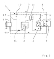
- Fig. 1 denotes the cooling system
- 2 the drive motor and 3 a Unit consisting of the gear 4 and the converter 5.
- Pv_wall the Power loss of the gearbox with Pv_get and the power loss of the converter designated Pv_wall
- the braking power of the retarder / arrester 6 is labeled Pv_ret.
- the arrows illustrate the flow direction of the Coolant or the transmission oil.
- the cooling system 1 comprises two cooling circuits 7, 8, the heat to a shared radiator / vehicle radiator 9 leave, through the first cooling circuit 7 of the engine 2, the transmission 4th and the transducer 5 and the second parallel cooling circuit 8 of the retarder 6 is cooled.
- the retarder / intarder 6 is designed so that it simultaneously acts as a pump and thus by the braking power in the medium of retarder / arrester 6 can dissipate introduced energy. Further is provided that the working fluid of the retarder / Intarders 6, the cooling liquid (Cooling water) of the cooling system 1, whereby the retarder 6 with the radiator 9 is directly connectable, so that the heated coolant directly to the radiator 9 is pumped.
- a water-oil heat exchanger 11 is provided, by means of its heat generated in the gearbox to the engine cooling circuit 7 is delivered.
- This construction ensures that the retarder cooling is independent from the engine temperature, which is regulated by a thermostat 10 becomes.
- the cooling liquid in the engine cooling circuit 7 is not the radiator 9, but via the line 12 and the engine cooling water pump 13 back to the engine. 2 fed.
- the coolant flows over the Line 14 through the radiator 9 and then by means of the engine cooling water pump 13 is supplied to the engine 2.
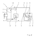
- the transmission 4 and the converter. 5 cooled by the cooling circuit 8 of the retarder 6.
- the difference to that Embodiment of Fig. 1 is that the transmission heat via the transmission heat exchanger 11 delivered to the cooling liquid of the retarder becomes.
- the transmission heat exchanger 11 is in this case the cooling circuit of the retarder arranged on the inlet side of the retarder, wherein the retarder in this case is preferably designed such that it is also in train operation generates an adjustable volume flow to circulate the coolant.
Landscapes
- Engineering & Computer Science (AREA)
- General Engineering & Computer Science (AREA)
- Mechanical Engineering (AREA)
- Chemical & Material Sciences (AREA)
- Combustion & Propulsion (AREA)
- Hybrid Electric Vehicles (AREA)
- Braking Arrangements (AREA)
Abstract
Description
Die vorliegende Erfindung betrifft ein Kühlsystem für ein Kraftfahrzeug,
umfassend einen Retarder gemäß dem Oberbegriff des Patentanspruchs 1.The present invention relates to a cooling system for a motor vehicle,
comprising a retarder according to the preamble of
Aus dem Stand der Technik ist die Verwendung von verschleißfreien Bremsen, insbesondere Retardern und im Getriebegehäuse angeordneten "Intardern" bekannt, um den hohen Anforderungen an die Bremsleistung zu genügen, wobei üblicherweise eine Hydraulikflüssigkeit als Bremsmedium dient. Hierbei entsteht der Nachteil, dass sich durch die Abfuhr der Bremsleistung auch das Getriebeöl erhitzt. Daher entsteht ein Regelungsbedarf der Temperatur des Getriebeöls.From the prior art, the use of wear-free Brakes, especially retarders and arranged in the transmission housing "Intardern" known to the high demands on the braking performance too suffice, usually a hydraulic fluid as the brake fluid serves. This creates the disadvantage that the removal of the braking power also heated the transmission oil. Therefore arises a regulation need of the Temperature of the transmission oil.
Aus der DE 198 54 389 A1 der Anmelderin ist ein Kühlsystem für den Antrieb von Kraftfahrzeugen mit einem Retarder bekannt, welches die durch den Betrieb des Retarders erzeugte Wärme im Ölkreis des Getriebes mit dem Ölstrom zu einem vorgesehenen Wärmetauscher transportiert, um diese an den Kühlkreislauf des Motors abzugeben. Hierbei kann es Situationen geben, beispielsweise bei Dauerbetrieb des Retarders, bei denen ein Wärmetauscher nicht ausreicht, um die gewünschte Kühlwirkung zu erzielen.DE 198 54 389 A1 of the applicant is a cooling system for the Propulsion of motor vehicles with a retarder known which by the operation of the retarder generated heat in the oil circuit of the transmission with the Oil flow transported to a designated heat exchanger to this to dispense the cooling circuit of the engine. There may be situations for example, during continuous operation of the retarder, in which a heat exchanger insufficient to achieve the desired cooling effect.
Im Rahmen der DE 101 38 704 A1 der Anmelderin wird ein weiteres Kühlsystem vorgestellt, welches einen ersten Kühlkreis aufweist, umfassend eine Abfuhrleitung, die den Motor mit einem Radiator verbindet und wenigstens einen in der Abfuhrleitung angeordneten Wärmetauscher, wobei der Wärmetauscher einen zweiten Kühlkreis, bestehend aus einem Getriebe und/oder Retarder versorgt. Hierbei ist der zweite Kühlkreis in wenigstens zwei Teilkühlkreise unterteilt, welche im Bedarfsfall, beispielsweise bei Retarderbetrieb oder Zug- und Schubbetrieb des Getriebes, kombiniert oder getrennt eingesetzt werden. Zudem kann ein zweiter Radiator vorgesehen sein, um die Kühlwirkung zu erhöhen.In the context of DE 101 38 704 A1 of the Applicant is another Cooling system presented, which has a first cooling circuit comprising a discharge line that connects the engine to a radiator and at least a arranged in the discharge line heat exchanger, wherein the heat exchanger a second cooling circuit consisting of a transmission and / or Retarder supplied. Here, the second cooling circuit is in at least two partial cooling circuits subdivided, which in case of need, for example, at Retarderbetrieb or Pulling and pushing operation of the gearbox, combined or used separately become. In addition, a second radiator may be provided to the cooling effect to increase.
Aus der DE 3713580 C1 ist eine Antriebsanlage mit einem hydrodynamischen Primärretarder bekannt, die aus einem Antriebsmotor und einem Kühlsystem besteht, bei der der hydrodynamische Retarder mit der Kurbelwelle in dauernder Drehverbindung ist und durch das Kühlmittel (Kühlwasser) selbst betrieben wird. Hierbei übernimmt der Retarder auch im ungebremsten Zustand die Funktion einer Kühlmittelumwälzpumpe; der Retarderbetrieb erfolgt durch Umschaltung einer Ventilkombination zwischen Retarder und Motor. Für den Fall einer Anhebung der Betriebstemperatur des Motors muss bei dieser Konstruktion auch das Getriebe für höhere Temperaturen ausgelegt werden.From DE 3713580 C1 is a drive system with a hydrodynamic Primary retarder known, consisting of a drive motor and a cooling system exists, in which the hydrodynamic retarder with the crankshaft in continuous rotary joint is and by the coolant (cooling water) itself is operated. Here, the retarder takes over even in the unbraked state the function of a coolant circulation pump; the retarder operation is carried out by Switching a valve combination between retarder and engine. For the Case of raising the operating temperature of the engine must be in this design Also, the gearbox can be designed for higher temperatures.
Die Betriebstemperaturen der Antriebsmotoren wurden in den vergangenen Jahren aus verschiedenen Gründen angehoben, wobei die Motorbetriebstemperatur über das Motorthermostatventil geregelt wird. Hierbei kann ein Getriebe mit einem Wasser-Öl-Getriebewärmetauscher die speziell im Retarderbetrieb anfallende Wärme nur an den Wasser-Kühlerkreislauf abgeben.The operating temperatures of the drive motors have been in the past Years raised for various reasons, the engine operating temperature is controlled by the engine thermostatic valve. This can be a Transmission with a water-oil transmission heat exchanger specifically in the retarder mode dissipate heat only to the water cooler circuit.
Bei einem einfachen Kühlkreislauf gibt die Motorbetriebstemperatur die Mindesttemperatur des Getriebes vor. In einem einfachen Getriebekühlkreislauf bestimmt somit die Motorbetriebstemperatur die Wärmeauslegung des Getriebes. Hierbei kann das Getriebe über den Wasser-Öl-Getriebewärmetauscher Wärme nur bei Vorhandensein einer Temperaturdifferenz Öl zu Wasser abgeben, wobei die maximale Kühlwassertemperatur von der Siedetemperatur des unter Druck stehenden Kühlwassers vorgegeben ist. Dies bedeutet, dass im Retarderbetrieb die momentan entstehende Wärme nur mit dem Kühlwasservolumenstrom und der maximalen Temperaturdifferenz Kühlwassersiedetemperatur zu Motorbetriebstemperatur abgegeben werden kann. Steigt die Motorbetriebstemperatur bei Beibehaltung des Kühlwasserdrucks (d.h. keine Erhöhung der Siedetemperatur), wird die maximal momentan abführbare Wärmemenge verringert. Damit kann der Einsatz eines Retarders/Intarders im Getriebe bei weiteren Motortemperaturerhöhungen unmöglich werden. Ein weiteres Problem besteht darin, dass eine Auslegung des Getriebes für höhere Temperaturen erfolgen muss. Ferner wird bei den bestehenden Kühlsystemen die im Zugbetrieb zur Verfügung stehende maximale Kühlleistung des Radiators durch das Schließen des Thermostaten nicht voll genutzt.In a simple refrigeration cycle, the engine operating temperature is Minimum temperature of the gearbox before. In a simple transmission cooling circuit Thus determines the engine operating temperature, the thermal design of the Transmission. Here, the transmission via the water-oil transmission heat exchanger Heat only in the presence of a temperature difference Deliver oil to water, with the maximum cooling water temperature of the boiling point of the pressurized cooling water is specified. This means that in the retarder operation, the currently occurring heat only with the cooling water volume flow and the maximum temperature difference Cooling water boiling temperature are delivered to engine operating temperature can. Increases the engine operating temperature while maintaining the cooling water pressure (i.e., no increase in boiling temperature) becomes the maximum instantaneous reduced amount of heat dissipated. Thus, the use of a retarder / Intarders impossible in the gearbox with further engine temperature increases become. Another problem is that a design of the transmission must be for higher temperatures. Furthermore, in the existing Cooling systems the available in train operation maximum cooling capacity the radiator is not fully utilized by closing the thermostat.
Nach dem Stand der Technik ist der Radiator eines Kühlsystems derart ausgelegt, dass er im Retarderbetrieb bei regelndem Kühlsystem für den Fall eines momentanen Leistungsanfalls die Kühlwassertemperatur unterhalb der Kühlwassersiedetemperatur halten und den mittleren Wärmeeintrag bei bestimmten Abnahmebedingungen (z. B. Retarderzyklen) abführen kann.In the prior art, the radiator of a cooling system is such designed to be in retarder operation with regulating cooling system in case of a momentary power surge the cooling water temperature below the Keep cooling water boiling temperature and the average heat input at certain Acceptance conditions (eg retarder cycles).
In der Praxis kann der Fall eintreten, dass die Kühlleistung im nicht regelnden Kühlsystem für die Kühlung ausreicht und das Getriebe im regelnden System zu heiß wird, so dass ein Zusatzkühler erforderlich wird. Dies bedeutet, dass der Radiator, der Lüfter und die Pumpleistung der Motorkühlmittelpumpe zur Kühlung des Fahrzeuges ausreichen, wobei durch den Thermostaten die maximale Leistungsabfuhr verhindert wird.In practice, the case may occur that the cooling capacity in the non-regulating Cooling system sufficient for cooling and the transmission in the regulatory System gets too hot, so an additional cooler is required. This means, that the radiator, the fan and the pump power of the engine coolant pump sufficient for cooling the vehicle, with the thermostat the maximum power dissipation is prevented.
Der vorliegenden Erfindung liegt die Aufgabe zugrunde, ein Kühlsystem anzugeben, welches eine effektive Kühlung eines Retarders ohne zusätzliche Kühlvorrichtungen ermöglicht.The present invention is based on the object, a cooling system specify which effective cooling of a retarder without additional Cooling devices allows.
Diese Aufgabe wird durch die Merkmale des Patentanspruchs 1 gelöst.
Weitere Ausgestaltungen und Vorteile gehen aus den Unteransprüchen hervor.This object is solved by the features of
Demnach wird ein Kühlsystem vorgeschlagen, bei dem der Retarder/Intarder einen zum Motorkühlkreislauf parallelen Kühlkreislauf aufweist, derart, dass die Retarderkühlung unabhängig von der Motortemperatur ist. Hierbei wird die Wärme beider Kühlkreisläufe über denselben Radiator/Fahrzeugkühler abgeführt.Accordingly, a cooling system is proposed in which the retarder / Intarder having a cooling circuit parallel to the engine cooling circuit, in such a way that the retarder cooling is independent of the engine temperature. in this connection the heat of both cooling circuits is via the same radiator / vehicle radiator dissipated.
Gemäß der Erfindung wird ein Retarder/Intarder so konstruiert, dass er gleichzeitig als Pumpe wirkt und somit die durch die Bremsleistung in das Medium des Retarders eingebrachte Energie abtransportieren kann. Hierbei wird vom Retarder/Intarder nur im Retarderbetrieb ein großer Volumenstrom über den Radiator geleitet. Vorzugsweise kann der Retarder als regelbare Pumpe ausgebildet sein, so dass die Betriebstemperatur geregelt werden kann.According to the invention, a retarder / intarder is constructed so that it simultaneously acting as a pump and thus by the braking power in the medium the retarder can dissipate introduced energy. This is from Retarder / Intarder only in Retarderbetrieb a large volume flow over passed the radiator. Preferably, the retarder as a controllable pump be formed so that the operating temperature can be controlled.
Im Rahmen einer besonders vorteilhaften Ausführungsform wird vorgeschlagen, einen Retarder/Intarder zu verwenden, dessen Arbeitsmedium die Kühlflüssigkeit (Kühlwasser) des Kühlsystems ist, und diesen direkt mit dem Radiator/Kühler zu verbinden, so dass die erhitzte Kühlflüssigkeit direkt zum Radiator/Kühler gepumpt wird, wobei als Kühler der vorhandene Fahrzeugkühler verwendet wird.In a particularly advantageous embodiment, it is proposed to use a retarder / Intarder whose working medium the Coolant (cooling water) of the cooling system, and this directly with the Radiator / cooler to connect, so that the heated coolant directly to the Radiator / radiator is pumped, being used as a cooler of the existing vehicle radiator is used.
Durch die erfindungsgemäße Konzeption ist der Motor durch die ohnehin vorhandene Kühlwasserpumpe vom Retarderkühlkreislauf losgelöst und somit bei beliebigen Motortemperaturen betreibbar. Die Regelung der Motortemperatur bleibt hierbei alleine dem Motorhersteller mit der Wahl des Thermostaten vorbehalten. Ferner kann vom Retarder im Retarderbetrieb die gesamte Wärmekapazität der vorhandenen Kühlwassermenge sowie die Kühlkapazität des Radiators/Fahrzeugkühlers genutzt werden, wobei ein zusätzlicher Öl-Wasser-Wärmetauscher für den Retarder in vorteilhafter Weise vermieden wird. Die Regelung der Motortemperatur kann gemäß der Erfindung ohne Thermostaten über die Kühlwasserpumpe erfolgen, wenn diese als regelbare Pumpe ausgebildet ist. Due to the concept of the invention, the engine is by anyway existing cooling water pump detached from the retarder cooling circuit and thus operable at any engine temperatures. The regulation of the engine temperature This is left to the engine manufacturer alone with the choice of thermostat Reserved. Furthermore, from the retarder in the retarder the entire Heat capacity of the existing amount of cooling water and the cooling capacity the radiator / vehicle radiator are used, with an additional Oil-water heat exchanger for the retarder avoided in an advantageous manner becomes. The control of the engine temperature can according to the invention without Thermostats via the cooling water pump, if this as controllable Pump is formed.
Eine vorteilhafte Weiterbildung der Erfindung sieht vor, dass neben der Retarderkühlung auch die Getriebekühlung unabhängig von der Motortemperatur ist. Dies wird dadurch erreicht, dass der Getriebewärmetauscher (Öl-Wasser Wärmetauscher) die Wärme an den Kühlkreislauf des Retarders abgibt. Zu diesem Zweck ist der Getriebewärmetauscher am Kühlkreislauf des Retarders an der Eintrittsseite des Retarders angeordnet, wobei der Retarder in diesem Fall derart ausgelegt ist, dass er auch im Zugbetrieb einen Volumenstrom erzeugt.An advantageous development of the invention provides that in addition to the Retarder cooling also the transmission cooling independent of the engine temperature is. This is achieved by the fact that the transmission heat exchanger (oil-water Heat exchanger) which emits heat to the cooling circuit of the retarder. For this purpose, the transmission heat exchanger on the cooling circuit of Retarders are arranged at the entrance side of the retarder, with the retarder in this case is designed such that it also in the train operation a volume flow generated.
Das Getriebe kann gemäß der Erfindung in vorteilhafter Weise bei wesentlich niedrigeren Temperaturen, als es nach dem Stand der Technik üblich ist, betrieben werden. Dies bedeutet, dass das Getriebeöl aufgrund der geringeren Erwärmung einer geringeren Ölalterung ausgesetzt ist, was sich auf die Dauerfestigkeit positiv auswirkt.The transmission can according to the invention in an advantageous manner at substantially lower temperatures than usual in the art is to be operated. This means that the gear oil due to the lower Heating is exposed to a lower oil aging, which affects the Fatigue strength has a positive effect.
Ferner kann das gesamte Kühlwasser als Speichermedium für die Dämpfung von Wärmeleistungsspitzen verwendet werden; hierbei kann die hohe Wärmekapazität des Wassers zur schnellen Wärmeabfuhr genutzt werden. Theoretisch ist eine Abkühlung des Getriebes im Re-/Intarderbetrieb ebenfalls möglich.Furthermore, the entire cooling water as a storage medium for the Damping of thermal power peaks are used; Here, the high heat capacity of the water can be used for rapid heat dissipation. Theoretically, a cooling of the transmission in Re- / Intarderbetrieb is also possible.
Ein weiterer Vorteil des erfindungsgemäßen Kühlsystems besteht darin, dass keine zusätzlichen aktiven Komponenten wie z.B. Pumpen benötigt werden, was zu einer Kosten und Komplexitätsreduzierung führt.Another advantage of the cooling system according to the invention is that no additional active components, e.g. Pumps are needed which leads to a cost and complexity reduction.
Gemäß der Erfindung kann der Fahrzeugkühler/Radiator derart ausgelegt sein, dass bei jedem Re-/Intarderbetriebspunkt sämtliche anfallenden Bremsleistungen abführbar sind, um eine Erwärmung des Getriebes im Retarderbetrieb zu vermeiden. According to the invention, the vehicle radiator / radiator can be designed in this way be that at each re / intarder operating point all accumulating Braking are dissipated to a heating of the transmission in the retarder mode to avoid.
Im Rahmen einer weiteren Ausführungsform kann der Retarder/Intarder (dessen Arbeitsmedium die Kühlflüssigkeit ist) in den bestehenden Kühlkreislauf integriert werden, ohne direkt mit dem Radiator verbunden zu sein.In a further embodiment, the retarder / intarder (whose working fluid is the cooling liquid) in the existing cooling circuit integrated without being directly connected to the radiator.
Die Erfindung wird im Folgenden anhand der beigefügten Figuren beispielhaft näher erläutert. Es stellen dar:
- Fig. 1
- eine schematische Ansicht des Aufbaus eines Kühlsystems gemäß einer ersten bevorzugten Ausführungsform der Erfindung, bei der die Retarderkühlung unabhängig von der Motorkühlung ist; und
- Fig. 2
- eine schematische Ansicht des Aufbaus eines Kühlsystems gemäß einer zweiten bevorzugten Ausführungsform der Erfindung, bei der die Retarderkühlung und die Getriebekühlung unabhängig von der Motorkühlung sind.
- Fig. 1
- a schematic view of the structure of a cooling system according to a first preferred embodiment of the invention, wherein the retarder is independent of the engine cooling; and
- Fig. 2
- a schematic view of the structure of a cooling system according to a second preferred embodiment of the invention, in which the retarder cooling and the transmission cooling are independent of the engine cooling.
In Fig. 1 bezeichnet 1 das Kühlsystem, 2 den Antriebsmotor und 3 eine
Einheit bestehend aus dem Getriebe 4 und dem Wandler 5. Ferner wird die
Verlustleistung des Getriebes mit Pv_get und die Verlustleistung des Wandlers
mit Pv_wand bezeichnet; die Bremsleistung des Retarders/lntarders 6 wird
mit Pv_ret bezeichnet. Die Pfeile veranschaulichen die Flussrichtung des
Kühlmittels bzw. des Getriebeöls.In Fig. 1, 1 denotes the cooling system, 2 the drive motor and 3 a
Unit consisting of the
Gemäß der Erfindung umfasst das Kühlsystem 1 zwei Kühlkreisläufe 7,
8, die die Wärme an einen gemeinsam genutzten Radiator/Fahrzeugkühler 9
abgeben, wobei durch den ersten Kühlkreislauf 7 der Motor 2, das Getriebe 4
und der Wandler 5 und durch den zweiten parallelen Kühlkreislauf 8 der Retarder
6 gekühlt wird. According to the invention, the
Im Rahmen der in Fig. 1 gezeigten Ausführungsform des erfindungsgemäßen
Kühlsystems 1 ist der Retarder/Intarder 6 so konstruiert, dass er gleichzeitig
als Pumpe wirkt und somit die durch die Bremsleistung in das Medium
des Retarders/lntarders 6 eingebrachte Energie abtransportieren kann. Ferner
ist vorgesehen, dass als Arbeitsmedium des Retarders/Intarders 6 die Kühlflüssigkeit
(Kühlwasser) des Kühlsystems 1 dient, wodurch der Retarder 6 mit
dem Radiator 9 direkt verbindbar ist, so dass die erhitzte Kühlflüssigkeit direkt
zum Radiator 9 gepumpt wird.In the context of the embodiment of the invention shown in FIG
In dem gezeigten Beispiel ist ein Wasser-Öl-Wärmetauscher 11 vorgesehen,
mittels dessen im Getriebe erzeugte Wärme an den Motorkühlkreislauf
7 abgegeben wird.In the example shown, a water-
Durch diese Konstruktion wird erreicht, dass die Retarderkühlung unabhängig
von der Motortemperatur ist, welche von einem Thermostaten 10 geregelt
wird. Wenn die Motortemperatur unterhalb der Betriebstemperatur liegt,
wird die Kühlflüssigkeit im Motorkühlkreislauf 7 nicht dem Radiator 9, sondern
über die Leitung 12 und die Motorkühlwasserpumpe 13 wieder dem Motor 2
zugeführt. Bei erreichter Betriebstemperatur fließt die Kühlflüssigkeit über die
Leitung 14 durch den Radiator 9 und wird anschließend mittels der Motorkühlwasserpumpe
13 dem Motor 2 zugeführt.This construction ensures that the retarder cooling is independent
from the engine temperature, which is regulated by a
Bei dem in Fig. 2 gezeigten Ausführungsbeispiel (gleiche Bezugszeichen
bezeichnen gleiche Bauteile) werden das Getriebe 4 und der Wandler 5
durch den Kühlkreislauf 8 des Retarders 6 gekühlt. Der Unterschied zu dem
Ausführungsbeispiel aus Fig. 1 besteht darin, dass die Getriebewärme über
den Getriebewärmetauscher 11 an die Kühlflüssigkeit des Retarders abgegeben
wird. Der Getriebewärmetauscher 11 ist hierbei am Kühlkreislauf des Retarders
an der Eintrittsseite des Retarders angeordnet, wobei der Retarder in
diesem Fall vorzugsweise derart ausgelegt ist, dass er auch im Zugbetrieb
einen regelbaren Volumenstrom erzeugt, um das Kühlmittel umzuwälzen.In the embodiment shown in Fig. 2 (same reference numerals
denote the same components), the
Durch die mittels der erfindungsgemäßen Konzeption nach Fig. 2 realisierbare Unabhängigkeit der Kühlung von Motor und Getriebe wird eine Auslegung der Motoren für höhere Temperaturen ermöglicht, ohne die Lebensdauer und die optimale Kühlung von Getrieben, die einen Retarder umfassen, zu beeinflussen.By realizable by means of the inventive conception of FIG Independence of the cooling of engine and transmission becomes a design which allows motors for higher temperatures, without the life and the optimal cooling of transmissions comprising a retarder influence.
Selbstverständlich fällt auch jede konstruktive Ausbildung, insbesondere jede räumliche Anordnung der Kühlsystem- bzw. Kühlkreiselement , an sich sowie zueinander und soweit technisch sinnvoll, unter den Schutzumfang der vorliegenden Ansprüche, ohne die Funktion des Kühlsystems, wie sie in den Ansprüchen angegeben ist, zu beeinflussen, auch wenn diese Ausbildungen nicht explizit in den Figuren oder in der Beschreibung dargestellt sind. Of course, any constructive training, especially any spatial arrangement of the cooling system or cooling circuit element, in itself as well as to each other and as far as technically reasonable, under the scope of protection of present claims, without the function of the cooling system, as shown in the Claims is to influence, even if these training are not explicitly shown in the figures or in the description.
- 11
- Kühlsystemcooling system
- 22
- Motorengine
- 33
- Einheit aus Getriebe und WandlerUnit of gear and converter
- 44
- Getriebetransmission
- 55
- Wandlerconverter
- 66
- Retarder/IntarderRetarder / intarder
- 77
- KühlkreislaufCooling circuit
- 88th
- KühlkreislaufCooling circuit
- 99
- Radiator/KühlerRadiator / cooler
- 1010
- Thermostatthermostat
- 1111
- GetriebewärmetauscherTransmission heat exchanger
- 1212
- Leitungmanagement
- 1313
- KühlwasserpumpeCooling water pump
- 1414
- Leitungmanagement
Claims (12)
Applications Claiming Priority (2)
| Application Number | Priority Date | Filing Date | Title |
|---|---|---|---|
| DE200410018227 DE102004018227A1 (en) | 2004-04-15 | 2004-04-15 | cooling system |
| DE102004018227 | 2004-04-15 |
Publications (2)
| Publication Number | Publication Date |
|---|---|
| EP1586754A1 true EP1586754A1 (en) | 2005-10-19 |
| EP1586754B1 EP1586754B1 (en) | 2009-04-29 |
Family
ID=34934648
Family Applications (1)
| Application Number | Title | Priority Date | Filing Date |
|---|---|---|---|
| EP20050007080 Ceased EP1586754B1 (en) | 2004-04-15 | 2005-03-31 | Cooling system |
Country Status (2)
| Country | Link |
|---|---|
| EP (1) | EP1586754B1 (en) |
| DE (2) | DE102004018227A1 (en) |
Cited By (4)
| Publication number | Priority date | Publication date | Assignee | Title |
|---|---|---|---|---|
| CN107781330A (en) * | 2017-11-17 | 2018-03-09 | 潍柴动力股份有限公司 | Vehicle matches the cooling system and automobile of Retarder |
| EP3815948A1 (en) * | 2019-11-01 | 2021-05-05 | Volvo Truck Corporation | A combined cooling and water braking system for a vehicle, and a method for cooling a propulsion device of a vehicle and water braking a pair of wheels of a vehicle |
| CN112943438A (en) * | 2019-11-26 | 2021-06-11 | 陕西重型汽车有限公司 | Pilot-controlled hydraulic retarder cooling system for commercial vehicle |
| CN115306534A (en) * | 2021-05-06 | 2022-11-08 | 陕西汽车集团股份有限公司 | Vehicle double-radiator cooling system |
Families Citing this family (3)
| Publication number | Priority date | Publication date | Assignee | Title |
|---|---|---|---|---|
| DE102006010247B4 (en) | 2006-03-02 | 2019-12-19 | Man Truck & Bus Se | Drive unit with heat recovery |
| SE542998C2 (en) | 2018-05-24 | 2020-09-22 | Scania Cv Ab | A cooling system for an engine and a water retarder |
| WO2023139070A1 (en) * | 2022-01-21 | 2023-07-27 | Liebherr-Components Biberach Gmbh | Electrical multi-phase machine |
Citations (4)
| Publication number | Priority date | Publication date | Assignee | Title |
|---|---|---|---|---|
| WO1995001500A1 (en) | 1993-07-01 | 1995-01-12 | Scania Cv Aktiebolag | Cooling system for a vehicle equipped with a retarder |
| US5657838A (en) * | 1994-03-11 | 1997-08-19 | Voith Turbo Gmbh & Co. Kg | Drive unit and method for operating a drive unit |
| DE19641558A1 (en) * | 1996-10-09 | 1998-04-16 | Voith Turbo Kg | Method and control for regulating the cooling circuit of a vehicle by means of a thermally controlled water pump |
| DE19854389A1 (en) * | 1998-11-25 | 2000-05-31 | Zahnradfabrik Friedrichshafen | Cooling circuit |
-
2004
- 2004-04-15 DE DE200410018227 patent/DE102004018227A1/en not_active Withdrawn
-
2005
- 2005-03-31 EP EP20050007080 patent/EP1586754B1/en not_active Ceased
- 2005-03-31 DE DE200550007172 patent/DE502005007172D1/en active Active
Patent Citations (4)
| Publication number | Priority date | Publication date | Assignee | Title |
|---|---|---|---|---|
| WO1995001500A1 (en) | 1993-07-01 | 1995-01-12 | Scania Cv Aktiebolag | Cooling system for a vehicle equipped with a retarder |
| US5657838A (en) * | 1994-03-11 | 1997-08-19 | Voith Turbo Gmbh & Co. Kg | Drive unit and method for operating a drive unit |
| DE19641558A1 (en) * | 1996-10-09 | 1998-04-16 | Voith Turbo Kg | Method and control for regulating the cooling circuit of a vehicle by means of a thermally controlled water pump |
| DE19854389A1 (en) * | 1998-11-25 | 2000-05-31 | Zahnradfabrik Friedrichshafen | Cooling circuit |
Cited By (9)
| Publication number | Priority date | Publication date | Assignee | Title |
|---|---|---|---|---|
| CN107781330A (en) * | 2017-11-17 | 2018-03-09 | 潍柴动力股份有限公司 | Vehicle matches the cooling system and automobile of Retarder |
| CN107781330B (en) * | 2017-11-17 | 2024-02-20 | 潍柴动力股份有限公司 | Heat dissipation system of hydraulic retarder matched with whole car and car |
| EP3815948A1 (en) * | 2019-11-01 | 2021-05-05 | Volvo Truck Corporation | A combined cooling and water braking system for a vehicle, and a method for cooling a propulsion device of a vehicle and water braking a pair of wheels of a vehicle |
| WO2021083532A1 (en) * | 2019-11-01 | 2021-05-06 | Volvo Truck Corporation | A combined cooling and water braking system for a vehicle, and a method for cooling a propulsion device of a vehicle and water braking a pair of wheels of a vehicle |
| CN112758062A (en) * | 2019-11-01 | 2021-05-07 | 沃尔沃卡车集团 | Combined cooling and waterbrake system for a vehicle and method of cooling a propulsion device of a vehicle and a pair of wheels of a waterbrake vehicle |
| US11697341B2 (en) | 2019-11-01 | 2023-07-11 | Volvo Truck Corporation | Combined cooling and water braking system for a vehicle, and a method for cooling a propulsion device of a vehicle and water braking a pair of wheels of a vehicle |
| CN112758062B (en) * | 2019-11-01 | 2024-04-16 | 沃尔沃卡车集团 | Combined cooling and waterbrake system for a vehicle and method of cooling a propulsion device of a vehicle and a pair of wheels of a waterbrake vehicle |
| CN112943438A (en) * | 2019-11-26 | 2021-06-11 | 陕西重型汽车有限公司 | Pilot-controlled hydraulic retarder cooling system for commercial vehicle |
| CN115306534A (en) * | 2021-05-06 | 2022-11-08 | 陕西汽车集团股份有限公司 | Vehicle double-radiator cooling system |
Also Published As
| Publication number | Publication date |
|---|---|
| DE502005007172D1 (en) | 2009-06-10 |
| DE102004018227A1 (en) | 2005-11-17 |
| EP1586754B1 (en) | 2009-04-29 |
Similar Documents
| Publication | Publication Date | Title |
|---|---|---|
| EP2035267B1 (en) | Hydrodynamic retarder | |
| EP1586754B1 (en) | Cooling system | |
| DE10301314A1 (en) | Cooling circuit, in particular for a motor vehicle transmission | |
| DE102017207159A1 (en) | DRIVE TRAVEL HEAT MANAGEMENT SYSTEM AND METHOD | |
| DE102010046460A1 (en) | Multi-zone heat exchanger for use in a vehicle cooling system | |
| EP2300696A1 (en) | Transmission oil circuit | |
| EP1308359A2 (en) | Hydrodynamic retarder | |
| DE102011078088A1 (en) | cooling system | |
| DE102008030969A1 (en) | Flow Control | |
| WO2017050724A1 (en) | Powertrain having an automatic transmission or automated manual transmission, an oil supply system and a hydrodynamic retarder | |
| DE10332907A1 (en) | Automotive coolant circuit with pump and retarder | |
| DE102010009757A1 (en) | Vehicle cooling circuit, particularly engine cooling circuit, has cooling medium that is circulated in vehicle cooling circuit by cooling medium pump, where vehicle drive motor is cooled by cooling medium | |
| DE102006036186A1 (en) | Vehicle's cooling circuit has auxiliary cooling medium pump, driven by drive unit provided in addition to driving engine, and connected in parallel to main cooling medium pump driven by driving engine | |
| EP1288093A1 (en) | Hydrodynamic retarder | |
| DE102013219786A1 (en) | Hydraulic system for a hydrodynamic machine | |
| DE102004061426A1 (en) | System and method for controlling the temperature of an engine oil of an internal combustion engine of a motor vehicle | |
| DE102005043802B4 (en) | Device for adjusting the temperature of steering oil in a motor vehicle | |
| WO2019091949A1 (en) | Drive device having a coolant circuit for a motor vehicle | |
| DE19609150A1 (en) | Vehicle drive unit with hydrodynamic retarder | |
| DE19951731A1 (en) | Retarder system | |
| DE10138704A1 (en) | Cooling system for vehicle drive, has second cooling circuit divided into sub-circuits that can be used together or separately as required, e.g. for retarder, traction and engine braking operation | |
| DE202019005478U1 (en) | Brake system for motor vehicles | |
| DE102009000777A1 (en) | Gear box i.e. stepless gearbox, efficiency improving method for agricultural vehicle, involves interrupting feed stream to heat exchanger by valve when oil temperature reaches to preset temperature, and deactivating bridging of cooler | |
| DE10058110A1 (en) | Automatic transmission for utility vehicles has integral heat exchangers , e.g. water-cooled pipes or grooves, connected to vehicle cooling system | |
| DE19641559A1 (en) | Drive unit with thermally controlled water pump |
Legal Events
| Date | Code | Title | Description |
|---|---|---|---|
| PUAI | Public reference made under article 153(3) epc to a published international application that has entered the european phase |
Free format text: ORIGINAL CODE: 0009012 |
|
| AK | Designated contracting states |
Kind code of ref document: A1 Designated state(s): AT BE BG CH CY CZ DE DK EE ES FI FR GB GR HU IE IS IT LI LT LU MC NL PL PT RO SE SI SK TR |
|
| AX | Request for extension of the european patent |
Extension state: AL BA HR LV MK YU |
|
| 17P | Request for examination filed |
Effective date: 20051223 |
|
| AKX | Designation fees paid |
Designated state(s): DE SE |
|
| 17Q | First examination report despatched |
Effective date: 20080319 |
|
| GRAP | Despatch of communication of intention to grant a patent |
Free format text: ORIGINAL CODE: EPIDOSNIGR1 |
|
| GRAS | Grant fee paid |
Free format text: ORIGINAL CODE: EPIDOSNIGR3 |
|
| GRAA | (expected) grant |
Free format text: ORIGINAL CODE: 0009210 |
|
| AK | Designated contracting states |
Kind code of ref document: B1 Designated state(s): DE SE |
|
| REF | Corresponds to: |
Ref document number: 502005007172 Country of ref document: DE Date of ref document: 20090610 Kind code of ref document: P |
|
| REG | Reference to a national code |
Ref country code: SE Ref legal event code: TRGR |
|
| PLBE | No opposition filed within time limit |
Free format text: ORIGINAL CODE: 0009261 |
|
| STAA | Information on the status of an ep patent application or granted ep patent |
Free format text: STATUS: NO OPPOSITION FILED WITHIN TIME LIMIT |
|
| 26N | No opposition filed |
Effective date: 20100201 |
|
| PGFP | Annual fee paid to national office [announced via postgrant information from national office to epo] |
Ref country code: SE Payment date: 20160311 Year of fee payment: 12 |
|
| PGFP | Annual fee paid to national office [announced via postgrant information from national office to epo] |
Ref country code: DE Payment date: 20170329 Year of fee payment: 13 |
|
| PG25 | Lapsed in a contracting state [announced via postgrant information from national office to epo] |
Ref country code: SE Free format text: LAPSE BECAUSE OF NON-PAYMENT OF DUE FEES Effective date: 20170401 |
|
| REG | Reference to a national code |
Ref country code: DE Ref legal event code: R119 Ref document number: 502005007172 Country of ref document: DE |
|
| PG25 | Lapsed in a contracting state [announced via postgrant information from national office to epo] |
Ref country code: DE Free format text: LAPSE BECAUSE OF NON-PAYMENT OF DUE FEES Effective date: 20181002 |