EP1586729A1 - Hinge system - Google Patents
Hinge system Download PDFInfo
- Publication number
- EP1586729A1 EP1586729A1 EP04101563A EP04101563A EP1586729A1 EP 1586729 A1 EP1586729 A1 EP 1586729A1 EP 04101563 A EP04101563 A EP 04101563A EP 04101563 A EP04101563 A EP 04101563A EP 1586729 A1 EP1586729 A1 EP 1586729A1
- Authority
- EP
- European Patent Office
- Prior art keywords
- hook
- section
- hinge according
- hinge
- base
- Prior art date
- Legal status (The legal status is an assumption and is not a legal conclusion. Google has not performed a legal analysis and makes no representation as to the accuracy of the status listed.)
- Withdrawn
Links
Images


Classifications
-
- E—FIXED CONSTRUCTIONS
- E04—BUILDING
- E04B—GENERAL BUILDING CONSTRUCTIONS; WALLS, e.g. PARTITIONS; ROOFS; FLOORS; CEILINGS; INSULATION OR OTHER PROTECTION OF BUILDINGS
- E04B1/00—Constructions in general; Structures which are not restricted either to walls, e.g. partitions, or floors or ceilings or roofs
- E04B1/343—Structures characterised by movable, separable, or collapsible parts, e.g. for transport
- E04B1/344—Structures characterised by movable, separable, or collapsible parts, e.g. for transport with hinged parts
-
- E—FIXED CONSTRUCTIONS
- E05—LOCKS; KEYS; WINDOW OR DOOR FITTINGS; SAFES
- E05D—HINGES OR SUSPENSION DEVICES FOR DOORS, WINDOWS OR WINGS
- E05D1/00—Pinless hinges; Substitutes for hinges
- E05D1/04—Pinless hinges; Substitutes for hinges with guide members shaped as circular arcs
-
- E—FIXED CONSTRUCTIONS
- E05—LOCKS; KEYS; WINDOW OR DOOR FITTINGS; SAFES
- E05D—HINGES OR SUSPENSION DEVICES FOR DOORS, WINDOWS OR WINGS
- E05D1/00—Pinless hinges; Substitutes for hinges
- E05D1/06—Pinless hinges; Substitutes for hinges consisting of two easily-separable parts
Definitions
- the invention relates to a hinge including a first and second elongated element along an axis cooperating with each other, the section of the first element including a first body and a first free end in the form of a curved hook, the section of the second element including a second body and a second free end in the shape of a crooked hook.
- hinges There are many types of hinges, swivel generally around a cylindrical axis, which are used for various applications. To avoid the location of the solicitations at the opening and the closure, a type of hinge commonly used is the hinge called “piano hinge”. However this type of hinge does not withstand the demands of its weak anchorage. Finally the use of an axis or pin poses problems of deformation and seizure especially when these hinges are intended to support loads important and are exposed to the weather and dirt.
- US 5,329,667 discloses a hinge which do not use a stud.
- the operation of the device is based on the principle of the articulation of two profiles cylindrical around several common axes of rotation.
- An object of the invention is to provide a hinge which can work even in case of significant wear of cooperating elements.
- Another object of the invention is to provide a hinge in which the elements cooperate without play.
- the subject of the invention is a hinge including a first and second elongated members along an axis cooperating with each other, the section of the first element including a first body and a first free end in the form of a curved hook, the section of the second element including a second body and a second free end in the form of a curved hook, characterized in that the hook of the first end has a fold capable of cooperating with a free end of the hook the second element to form a single pivot axis between the first and the second element.
- the presence of the fold in the first hook, which is able to receive one end of the second hook, allows the two hinge elements to stay always in contact with each other and therefore avoid that there is play between the elements, even when said elements undergo wear.
- the hook of the first element has the shape of a first C, able to surround the hook of the second element.
- the first C includes a first and a second branch, the first branch being connected to the body of the first element while the distal end free of the second branch is extended by a branch to form the fold.
- the hook of the second element has also the shape of a C, comprising a first and a second branch, the first branch being connected to the body of the second element.
- This embodiment is advantageous because the elements hinge can be obtained by folding a metal sheet.
- cooperation between the two hinge elements can be obtained by suspending or inserting the hook of the second element in the channel set the hook of the first element.
- the branches of the first and second C are substantially parallel and the angle formed by the fold is substantially equal to 90 °.
- the branches of the first and second C are substantially convergent and the angle formed by the fold is substantially equal to 135 °.
- the hinge elements are made of a material resistant to corrosion such as stainless steel or aluminum or composite material strengthened.
- Hinge elements according to the invention can be used to build very quickly, using only one reduced number of elements and parts.
- FIG. 1 is shown in section, a hinge according to the invention, comprising a first element (4) cooperating with a second element (6) by interlocking the second element in the first element.
- the section of the first element (4) comprises a first body (8) one end of which ends with a hook (10).
- the hook (10) has the shape of a first C, comprising a first branch (12) and a second branch (14).
- the free end of the second branch (14) is curved towards the interior of the first C by a straight part (16) in forming a fold (18) at an angle substantially equal to 90 °.
- the first body (8) has the shape of a first L, whose the base (20) connects with the first limb (12) of the first hook (10) and whose shaft (22) is curved towards inside the L forming a C (23).
- the angle formed by the base (20) of the L and the first leg (12) of the hook (10) is substantially equal to 135 °.
- the section of the second element (6) comprises a body (24) one end of which ends with a hook (26).
- the hook (26) has the shape of a C, comprising a first branch (28), by which it connects to the body (24), and a second branch (30).
- the body (24) of the second element (6) has the shape of an L, the shaft (32) of which is connected to the first leg (28) of the hook (26) in making an angle of about 135 °.
- the base (34) of the L is curl inward of the L by defining a C (35).
- the right part (16) does not close the first hook (10) of the first element (4) than on a part of its width to allow pivoting and the assembly of the second element (6).
- the assembly is obtained by inserting the second hook (26) of the second element (6) inside the groove defined by the first hook (10) of the first element (4).
- the second branch (30) of the second hook (26) is then supported on the second branch (14) of the first hook (10) while the ridge (31) of the second leg (30) of the second hook (26) rests in the fold (18).
- the separation of the branches (28, 30) of the second hook (26) is substantially less than branches (12, 14) of the first hook (10).
- Construction parts (36), such as for example panels, can be attached to the first and second the backs of the Cs (23, 35) by fastening means known to those skilled in the art.
- the second element (6) is then brought into a intermediate position ( Figure 3) by a movement of pivoting counterclockwise.
- the only point of contact between the two elements (4, 6) made along the unique pivot axis, defined as being the intersection between the ridge (31) and the fold (18).
- the hinge elements are made of a material resistant to corrosion, by example in stainless steel or aluminum, or in one composite material reinforced with glass fibers, carbon or any other suitable material.
- the branches (12, 14) of the first hook (10) and the branches (28, 30) of the second hook (26) are substantially parallel and the angle of the fold (18) is about 90 °.
- the branches (12, 14) of the first hook (10) and the branches (28, 30) of the second hook (26) converge substantially towards each other, while the angle of the fold (18) is substantially equal to 135 °.
- FIG. 6 is a sectional view of another form of realization, advantageous in the case where the elements hinges are obtained by extrusion by means of a Faculty.
- the first element (4) comprises a hook (10) such that already described above and a body (8) comprising two branches (38, 40) extending substantially perpendicular to a base (42). Both branches (38, 40) thus define a groove suitable for receiving a construction element such as a panel (44).
- the base (42) is connected to the first branch (12) of the hook (10) at a corner.
- a branch reinforcement (46) extends between the first limb (12) hook (10) and the base (42).
- the second element (6) comprises a hook (26), as described above, and a body (24) defined by two branches (48, 50) extending perpendicularly to a base (52).
- the two branches (48, 50) thus define a groove.
- the base (52) is connected to the first branch (28) of the hook (26).
- a branch of reinforcement (54) also extends between the first leg (28) of the hook (26) and the base (52) of the body (24) to stiffen the second element (6).
- This embodiment is particularly interesting because it is possible to fix in a simple way prefabricated panels by simple insertion into the grooves.
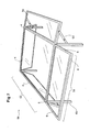
- Figure 7 is a perspective view of a construction (56), in this case a cover of pool, whose vertical walls (58) can be fold up at the right season.
- This construction (56) is erected using only elements profiles (4, 6) described above, except for the corner posts (60) which are simple hollow sections of any section, for example square.
- Construction (56) includes a fixed roof (62) whose bearing frame consists of the assembly of four elements (4).
- a cover element for example a polycarbonate panel (64) or any other material, is attached to the carrying frame.
- An advantage resulting from the use of the elements (4) to form the bearing frame is that the channel, defined between the shaft (22) of the L and the first branch (12) of the hook (10), plays the role of a gutter to collect rainwater (see Figure 1). A descent, which can possibly be fitted inside the poles angle (60) makes it possible to evacuate the water harvested in said gutter.
- the frame carrying the vertical wall (58) is to him obtained by the association of four elements (6) as described in Figure 1; this frame supports a panel (64), for example polycarbonate, fixed by means of appropriate fixation.
- the assembly of elements to form the bearing frame can be made by a miter cut, to using brackets, riveting or welding.
- the frame carrying the vertical wall (58), once assembled, is put in cooperation with the the fixed roof by interlocking or embedding the hook (26) inside the hook (10).
- a jack system (65) actuated in a manner pneumatic, hydraulic or electrical can be used to connect the corner posts (60) with each element (6) constituting the vertical side of the frame of the vertical wall (58).
- Figure 8 is a representation in section of one of the corners of the construction when the vertical walls were folded towards the low.
- the first branch (28) of the hook (26) of the second element (6) provides a better resistance to gusts of wind by accentuating the rigidity of the corner post (60) in the diagonal direction.
- a material sealing ring (66) is applied to the outer surface of the shaft (32) of the L and on the first branch (28) of the hook (26). This sealing material (66) on the one hand, to improve the hermetic integrity of the building when the vertical wall (58) is closed and, on the other hand, to cushion the shocks between the elements (6) and the corner posts (60) when closing, while reducing the coefficient of friction between elements (6) and the corner posts (60).
- Fig. 9 is another embodiment of body (24) of the second element (4) in which the shaft (22) of the L has a curvature in the shape of a corner post (60) of circular section.
Abstract
Description
L'invention se rapporte à une charnière incluant un premier et deuxième élément allongé suivant un axe coopérant l'un avec l'autre, la section du premier élément incluant un premier corps et une première extrémité libre en forme de crochet recourbé, la section du deuxième élément incluant un deuxième corps et une deuxième extrémité libre en forme de crochet recourbé.The invention relates to a hinge including a first and second elongated element along an axis cooperating with each other, the section of the first element including a first body and a first free end in the form of a curved hook, the section of the second element including a second body and a second free end in the shape of a crooked hook.
Il existe de nombreux types de charnières, pivotant généralement autour d'un axe cylindrique, qui sont utilisées pour diverses applications. Pour éviter la localisation des sollicitations à l'ouverture et la fermeture, un type de charnière couramment utilisé est la charnière dite « charnière piano ». Cependant ce type de charnière résiste mal aux sollicitations du fait de son faible ancrage. Enfin l'utilisation d'un axe ou broche pose des problèmes de déformation et de grippage surtout lorsque ces charnières sont destinées à supporter des charges importantes et sont exposées aux intempéries et aux saletés.There are many types of hinges, swivel generally around a cylindrical axis, which are used for various applications. To avoid the location of the solicitations at the opening and the closure, a type of hinge commonly used is the hinge called "piano hinge". However this type of hinge does not withstand the demands of its weak anchorage. Finally the use of an axis or pin poses problems of deformation and seizure especially when these hinges are intended to support loads important and are exposed to the weather and dirt.
Pour pallier ces inconvénients, des charnières continues ont été développées.To overcome these disadvantages, hinges continuous studies have been developed.
Le document US 5,329,667 décrit une charnière qui n'utilise pas de goujon. Le fonctionnement du dispositif repose sur le principe de l'articulation de deux profilés cylindriques autour de plusieurs axes de rotation communs.US 5,329,667 discloses a hinge which do not use a stud. The operation of the device is based on the principle of the articulation of two profiles cylindrical around several common axes of rotation.
Cependant ce genre de dispositif ne supprime pas totalement les problèmes d'usure des pièces car les deux éléments de charnière présentent une surface de contact importante d'où une usure élevée, qui peut engendrer des phénomènes de grippage et d'ovalisation. En raison de l'existence de plusieurs axes de rotation se développant sur différents points de la charnière, la charnière de l'art antérieur est donc particulièrement sujette à une abrasion par frottement des éléments. L'ovalisation des éléments de charnière peut alors créer du jeu entre ceux-ci. Ces phénomènes d'usure sont en outre aggravés lorsque ces charnières servent à faire pivoter des pièces de construction lourdes.However this kind of device does not remove totally the wear and tear of the parts because both hinge elements have a contact surface important, resulting in high wear, which can lead to seizure and ovalisation phenomena. Due to the existence of several axes of rotation developing on different points of the hinge, the hinge of the prior art is therefore particularly subject to frictional abrasion of the elements. The ovalization of hinge elements can then create play between these. These phenomena of wear are further aggravated when these hinges are used to rotate pieces of heavy construction.
Un but de l'invention est de fournir une charnière qui puisse fonctionner même en cas d'une usure importante des éléments coopérants.An object of the invention is to provide a hinge which can work even in case of significant wear of cooperating elements.
Un autre but de l'invention est de fournir une charnière dans laquelle les éléments coopèrent sans jeu.Another object of the invention is to provide a hinge in which the elements cooperate without play.
L'objet de l'invention est une charnière incluant un premier et deuxième élément allongés suivant un axe coopérants l'un avec l'autre, la section du premier élément incluant un premier corps et une première extrémité libre en forme de crochet recourbé, la section du deuxième élément incluant un deuxième corps et une deuxième extrémité libre en forme de crochet recourbé, caractérisée en ce que le crochet de la première extrémité comporte une pliure apte à coopérer avec une extrémité libre du crochet du deuxième élément pour former un axe de pivotement unique entre le premier et le deuxième élément.The subject of the invention is a hinge including a first and second elongated members along an axis cooperating with each other, the section of the first element including a first body and a first free end in the form of a curved hook, the section of the second element including a second body and a second free end in the form of a curved hook, characterized in that the hook of the first end has a fold capable of cooperating with a free end of the hook the second element to form a single pivot axis between the first and the second element.
La présence de la pliure dans le premier crochet, qui est apte à recevoir une extrémité du deuxième crochet, permet aux deux éléments faisant charnière de rester toujours en contact l'un avec l'autre et donc d'éviter qu'il n'y ait du jeu entre les éléments, même lorsque lesdits éléments subissent une usure.The presence of the fold in the first hook, which is able to receive one end of the second hook, allows the two hinge elements to stay always in contact with each other and therefore avoid that there is play between the elements, even when said elements undergo wear.
Un autre but de l'invention est de fournir une charnière facile à monter et démonter, mettant en oeuvre un nombre de pièces aussi réduit que possible et dont les éléments sont faciles à fabriquer. Dans une forme de réalisation particulière, le crochet du premier élément a la forme d'un premier C, apte à entourer le crochet du deuxième élément. Le premier C comprend une première et une deuxième branche, la première branche étant raccordé au corps du premier élément tandis que l'extrémité distale libre de la deuxième branche est prolongée par une branche pour former la pliure. Le crochet du deuxième élément a également la forme d'un C, comprenant une première et une deuxième branche, la première branche étant raccordé au corps du deuxième élément.Another object of the invention is to provide a hinge easy to assemble and disassemble, implementing a number of rooms as small as possible and whose elements are easy to manufacture. In a form of particular realization, the hook of the first element has the shape of a first C, able to surround the hook of the second element. The first C includes a first and a second branch, the first branch being connected to the body of the first element while the distal end free of the second branch is extended by a branch to form the fold. The hook of the second element has also the shape of a C, comprising a first and a second branch, the first branch being connected to the body of the second element.
Ce mode de réalisation est avantageux car les éléments faisant charnière peuvent être obtenus par pliage d'une tôle métallique. En outre, la coopération entre les deux éléments de charnière peut être obtenue en suspendant ou en insérant le crochet du deuxième élément dans le canal défini le crochet du premier élément.This embodiment is advantageous because the elements hinge can be obtained by folding a metal sheet. In addition, cooperation between the two hinge elements can be obtained by suspending or inserting the hook of the second element in the channel set the hook of the first element.
Dans une forme de réalisation particulière, les branches des premier et deuxième C sont sensiblement parallèles et l'angle formé par la pliure est sensiblement égal à 90°.In a particular embodiment, the branches of the first and second C are substantially parallel and the angle formed by the fold is substantially equal to 90 °.
Dans une forme de réalisation avantageuse, les branches des premier et deuxième C sont sensiblement convergentes et l'angle formé par la pliure est sensiblement égal à 135°. In an advantageous embodiment, the branches of the first and second C are substantially convergent and the angle formed by the fold is substantially equal to 135 °.
De façon préférée, les éléments faisant charnière sont réalisés en un matériau résistant à la corrosion tel que l'acier inoxydable ou l'aluminium ou en matériau composite renforcé.Preferably, the hinge elements are made of a material resistant to corrosion such as stainless steel or aluminum or composite material strengthened.
Les éléments faisant charnière selon l'invention peuvent être avantageusement employés pour ériger des constructions très rapidement, en ne faisant appel qu'à un nombre réduit d'éléments et de pièces d'apport.Hinge elements according to the invention can be used to build very quickly, using only one reduced number of elements and parts.
D'autres particularités et avantages de l'invention
ressortiront de la description détaillée de modes de
réalisation particuliers de l'invention, référence étant
faite aux figures annexées, dans lesquelles :
Sur la figure 1 est représentée en coupe, une charnière selon l'invention, comprenant un premier élément (4) coopérant avec un deuxième élément (6) par emboítement du deuxième élément dans le premier élément.In Figure 1 is shown in section, a hinge according to the invention, comprising a first element (4) cooperating with a second element (6) by interlocking the second element in the first element.
La section du premier élément (4) comprend un premier corps (8) dont une extrémité se termine par un crochet (10). Le crochet (10) a la forme d'un premier C, comprenant une première branche (12) et une deuxième branche (14). L'extrémité libre de la deuxième branche (14) se recourbe vers l'intérieur du premier C par une partie droite (16) en formant une pliure (18) selon un angle sensiblement égal à 90°. Le premier corps (8) a la forme d'un premier L, dont la base (20) se raccorde à la première branche (12) du premier crochet (10) et dont la hampe (22) se recourbe vers l'intérieur du L en formant un C (23). L'angle formé par la base (20) du L et la première branche (12) du crochet (10) est sensiblement égal à 135°.The section of the first element (4) comprises a first body (8) one end of which ends with a hook (10). The hook (10) has the shape of a first C, comprising a first branch (12) and a second branch (14). The free end of the second branch (14) is curved towards the interior of the first C by a straight part (16) in forming a fold (18) at an angle substantially equal to 90 °. The first body (8) has the shape of a first L, whose the base (20) connects with the first limb (12) of the first hook (10) and whose shaft (22) is curved towards inside the L forming a C (23). The angle formed by the base (20) of the L and the first leg (12) of the hook (10) is substantially equal to 135 °.
La section du deuxième élément (6) comprend un corps (24) dont une extrémité se termine par un crochet (26). Le crochet (26) a la forme d'un C, comprenant une première branche (28), par laquelle il se raccorde au corps (24), et une deuxième branche (30). Le corps (24) du deuxième élément (6) a la forme d'un L, dont la hampe (32) est raccordée à la première branche (28) du crochet (26) en faisant un angle d'environ 135°. La base (34) du L se recourbe vers l'intérieur du L en définissant un C (35).The section of the second element (6) comprises a body (24) one end of which ends with a hook (26). The hook (26) has the shape of a C, comprising a first branch (28), by which it connects to the body (24), and a second branch (30). The body (24) of the second element (6) has the shape of an L, the shaft (32) of which is connected to the first leg (28) of the hook (26) in making an angle of about 135 °. The base (34) of the L is curl inward of the L by defining a C (35).
On remarque que la partie droite (16) ne referme le premier crochet (10) du premier élément (4) que sur une partie de sa largeur afin de permettre le pivotement et l'assemblage du deuxième élément (6). L'assemblage est obtenu en insérant le deuxième crochet (26) du deuxième élément (6) à l'intérieur de la gorge définie par le premier crochet (10) du premier élément (4). La deuxième branche (30) du deuxième crochet (26) vient alors s'appuyer sur la deuxième branche (14) du premier crochet (10) pendant que l'arête (31) de la deuxième branche (30) du deuxième crochet (26) repose dans la pliure (18).Note that the right part (16) does not close the first hook (10) of the first element (4) than on a part of its width to allow pivoting and the assembly of the second element (6). The assembly is obtained by inserting the second hook (26) of the second element (6) inside the groove defined by the first hook (10) of the first element (4). The second branch (30) of the second hook (26) is then supported on the second branch (14) of the first hook (10) while the ridge (31) of the second leg (30) of the second hook (26) rests in the fold (18).
Afin de permettre la mise en charnière des premier et deuxième éléments (4, 6) et leur pivotement l'un par rapport à l'autre, l'écartement des branches (28, 30) du deuxième crochet (26) est sensiblement inférieur à celui des branches (12, 14) du premier crochet (10).In order to allow the hinge of the first and second elements (4, 6) and their pivoting one by compared to the other, the separation of the branches (28, 30) of the second hook (26) is substantially less than branches (12, 14) of the first hook (10).
Grâce à cette géométrie particulière des crochets , il n'est pas nécessaire d'utiliser une tige de liaison ou toute autre pièce intermédiaire, fixe ou mobile, pour faire pivoter le deuxième élément (6) par rapport au premier élément (4).Thanks to this particular geometry of the hooks, it it is not necessary to use a connecting rod or any other intermediate part, fixed or movable, to rotate the second element (6) relative to the first element (4).
Des pièces de construction (36), comme par exemple des panneaux, peuvent être fixées aux premier et deuxième éléments le dos des C (23, 35), par des moyens de fixation connus de l'homme du métier.Construction parts (36), such as for example panels, can be attached to the first and second the backs of the Cs (23, 35) by fastening means known to those skilled in the art.
L'enchaínement des figures 2, 3 et 4 illustre les positions relatives des éléments (4, 6) lors du mouvement de pivotement. The sequence of Figures 2, 3 and 4 illustrates the relative positions of elements (4, 6) during movement pivoting.
Dans la position initiale (figure 2), la deuxième branche (30) du deuxième crochet (26) repose, sur toute sa longueur, sur la deuxième branche (14) du premier crochet (10).In the initial position (Figure 2), the second branch (30) of the second hook (26) rests, over its entire length, on the second branch (14) of the first hook (10).
Le deuxième élément (6) est ensuite amené dans une position intermédiaire (figure 3) par un mouvement de pivotement dans le sens inverse des aiguilles d'une montre. Le seul point de contact entre les deux éléments (4, 6) se fait le long de l'axe unique de pivotement, défini comme étant l'intersection entre l'arête (31) avec la pliure (18).The second element (6) is then brought into a intermediate position (Figure 3) by a movement of pivoting counterclockwise. The only point of contact between the two elements (4, 6) made along the unique pivot axis, defined as being the intersection between the ridge (31) and the fold (18).
Dans la position finale (figure 4), après un pivotement de 90°, la deuxième branche (30) du deuxième crochet (26) vient s'appuyer contre la partie droite (16) prolongeant la deuxième branche (14) du premier crochet (10), tandis que l'arête (31) repose dans la pliure (18).In the final position (Figure 4), after a pivoting by 90 °, the second branch (30) of the second hook (26) comes to bear against the right part (16) extending the second branch (14) of the first hook (10), while the ridge (31) rests in the fold (18).
On observe que les deux éléments (4, 6) restent constamment en contact l'un avec l'autre, étant donné que le deuxième élément (6) se trouve « suspendu » au premier élément (4). Ainsi l'action de la gravité permet de compenser automatiquement l'usure de l'arête (31) et donc d'éviter qu'il n'y ait du jeu entre les éléments (4, 6).It is observed that the two elements (4, 6) remain constantly in contact with each other, since the second element (6) is "suspended" at the first element (4). So the action of gravity makes it possible to automatically compensate the wear of the edge (31) and therefore to avoid that there is clearance between the elements (4, 6).
Un autre avantage réside dans le fait qu'usure de l'arête (31) ne nuira pas au fonctionnement de la charnière en raison de la faible surface de contact entre les éléments (4, 6).Another advantage lies in the fact that the edge (31) will not affect the operation of the hinge because of the small contact area between elements (4, 6).
On note également que l'articulation est continue sur toute la longueur des deux éléments (4, 6), permettant ainsi de mieux répartir le poids et les forces exercés par des pièces de construction lourdes qui seraient fixées aux éléments (4, 6). We also note that the articulation is continuous on the entire length of the two elements (4, 6), allowing to better distribute the weight and forces exerted by heavy construction parts that would be attached to elements (4, 6).
Bien que les phénomènes de corrosion aient peu d'influence sur le fonctionnement de la charnière selon l'invention, pour des questions d'entretien, il est avantageux que les éléments faisant charnière soient réalisés en un matériau résistant à la corrosion, par exemple en acier inoxydable ou en aluminium, ou en un matériau composite renforcé par des fibres de verre, de carbone ou tout autre matériau adéquat.Although the corrosion phenomena have little influence on the operation of the hinge according to the invention, for maintenance purposes, it is advantageous that the hinge elements are made of a material resistant to corrosion, by example in stainless steel or aluminum, or in one composite material reinforced with glass fibers, carbon or any other suitable material.
Il est à souligner que la géométrie des éléments (4, 6), décrit dans la figure 1 est avantageuse d'un point de vue économique car elle peut être obtenue par pliage d'une tôle métallique, par exemple en acier inoxydable. Ainsi, il n'est pas nécessaire de mettre en oeuvre une filière, coûteuse dans le cas des pièces de grande dimension ou de petite série, pour donner la forme requise aux éléments (4, 6).It should be emphasized that the geometry of the elements (4, 6), described in Figure 1 is advantageous from a point of economic view because it can be obtained by folding a sheet metal, for example stainless steel. So, he it is not necessary to implement a sector, costly in the case of large parts or small series, to give the required form to the elements (4, 6).
Il est possible d'obtenir un angle de pivotement supérieur à 90° et allant jusqu'à sensiblement 135°, en modifiant l'angle de pliage des branches des crochets (10, 26) et celui de la pliure (18).It is possible to obtain a pivot angle greater than 90 ° and up to substantially 135 °, in modifying the angle of folding of the branches of the hooks (10, 26) and that of the fold (18).
Dans la première forme de réalisation de la charnière, représentée à la figure 1, les branches (12, 14) du premier crochet (10) et les branches (28, 30) du deuxième crochet (26) sont sensiblement parallèles et l'angle de la pliure (18) est d'environ 90°.In the first embodiment of the hinge, represented in FIG. 1, the branches (12, 14) of the first hook (10) and the branches (28, 30) of the second hook (26) are substantially parallel and the angle of the fold (18) is about 90 °.
Dans une seconde forme de réalisation des profilés, représentée à la figure 5, les branches (12, 14) du premier crochet (10) et les branches (28, 30) du deuxième crochet (26) convergent sensiblement l'une vers l'autre, tandis que l'angle de la pliure (18) est sensiblement égal à 135°. In a second embodiment of the profiles, represented in FIG. 5, the branches (12, 14) of the first hook (10) and the branches (28, 30) of the second hook (26) converge substantially towards each other, while the angle of the fold (18) is substantially equal to 135 °.
La figure 6 est une vue en coupe d'une autre forme de réalisation, avantageuse dans le cas où les éléments faisant charnière sont obtenus par extrusion au moyen d'une filière.FIG. 6 is a sectional view of another form of realization, advantageous in the case where the elements hinges are obtained by extrusion by means of a Faculty.
Le premier élément (4) comprend un crochet (10) tel que déjà décrit plus haut et un corps (8) comprenant deux branches (38, 40) s'étendant sensiblement perpendiculairement par rapport une base (42). Les deux branches (38, 40) définissent ainsi une rainure apte à recevoir un élément de construction tel qu'un panneau (44). La base (42) est raccordée à la première branche (12) du crochet (10) au niveau d'un coin. Afin de renforcer la résistance à la flexion du premier élément (4), une branche de renforcement (46) s'étend entre la première branche (12) du crochet (10) et la base (42).The first element (4) comprises a hook (10) such that already described above and a body (8) comprising two branches (38, 40) extending substantially perpendicular to a base (42). Both branches (38, 40) thus define a groove suitable for receiving a construction element such as a panel (44). The base (42) is connected to the first branch (12) of the hook (10) at a corner. To strengthen the flexural strength of the first element (4), a branch reinforcement (46) extends between the first limb (12) hook (10) and the base (42).
Le deuxième élément (6) comprend un crochet (26), comme décrit précédemment, et un corps (24) défini par deux branches (48, 50) s'étendant perpendiculairement à une base (52). Les deux branches (48, 50) définissent ainsi une rainure. La base (52) est raccordée à la première branche (28) du crochet (26). Une branche de renforcement (54) s'étend également entre la première branche (28) du crochet (26) et la base (52) du corps (24) afin de rigidifier le deuxième élément (6).The second element (6) comprises a hook (26), as described above, and a body (24) defined by two branches (48, 50) extending perpendicularly to a base (52). The two branches (48, 50) thus define a groove. The base (52) is connected to the first branch (28) of the hook (26). A branch of reinforcement (54) also extends between the first leg (28) of the hook (26) and the base (52) of the body (24) to stiffen the second element (6).
Cette forme de réalisation est particulièrement intéressante car il est possible de fixer de manière simple des panneaux préfabriqués par simple insertion dans les rainures.This embodiment is particularly interesting because it is possible to fix in a simple way prefabricated panels by simple insertion into the grooves.
La figure 7 est une vue en perspective d'une construction (56), en l'occurrence une couverture de piscine, dont les parois verticales (58) peuvent se rabattre vers le haut à la bonne saison. Cette construction (56) est érigée en employant uniquement des éléments profilés (4, 6) décrits précédemment, hormis pour les poteaux d'angle (60) qui sont de simples profilés creux de section quelconque, par exemple carrée.Figure 7 is a perspective view of a construction (56), in this case a cover of pool, whose vertical walls (58) can be fold up at the right season. This construction (56) is erected using only elements profiles (4, 6) described above, except for the corner posts (60) which are simple hollow sections of any section, for example square.
La construction (56) comprend une toiture fixe (62) dont le cadre portant est constitué par l'assemblage de quatre éléments (4). Un élément de couverture, par exemple un panneau en polycarbonate (64) ou en toute autre matériau, est fixé au cadre portant.Construction (56) includes a fixed roof (62) whose bearing frame consists of the assembly of four elements (4). A cover element, for example a polycarbonate panel (64) or any other material, is attached to the carrying frame.
Un avantage résultant de l'utilisation des éléments (4) pour former le cadre portant est que le canal, défini entre la hampe (22) du L et la première branche (12) du crochet (10), joue le rôle d'une gouttière pour recueillir les eaux de pluie (voir figure 1). Une descente, qui peut être éventuellement aménagée à l'intérieur des poteaux d'angle (60) permet d'évacuer l'eau récoltée dans ladite gouttière.An advantage resulting from the use of the elements (4) to form the bearing frame is that the channel, defined between the shaft (22) of the L and the first branch (12) of the hook (10), plays the role of a gutter to collect rainwater (see Figure 1). A descent, which can possibly be fitted inside the poles angle (60) makes it possible to evacuate the water harvested in said gutter.
Le cadre portant de la paroi verticale (58) est quant à lui obtenu par l'association de quatre éléments (6) comme décrit dans la figure 1 ; ce cadre soutient un panneau (64), par exemple en polycarbonate, fixé par des moyens de fixation appropriés. L'assemblage des éléments pour former le cadre portant peut se faire par une coupe en onglet, à l'aide d'équerres, par rivetage ou encore par soudage.The frame carrying the vertical wall (58) is to him obtained by the association of four elements (6) as described in Figure 1; this frame supports a panel (64), for example polycarbonate, fixed by means of appropriate fixation. The assembly of elements to form the bearing frame can be made by a miter cut, to using brackets, riveting or welding.
Le cadre portant de la paroi verticale (58), une fois assemblé, est mis en coopération avec le cadre portant de la toiture fixe par emboítement ou par enchâssement du crochet (26) à l'intérieur du crochet (10).The frame carrying the vertical wall (58), once assembled, is put in cooperation with the the fixed roof by interlocking or embedding the hook (26) inside the hook (10).
Optionnellement, afin d'éviter tout basculement involontaire de la paroi verticale (58) lorsqu'elle est en position ouverte et également pour faciliter son pivotement, un système de vérin (65), actionné de manière pneumatique, hydraulique ou encore électrique peut être employé pour relier les poteaux d'angle (60) avec chaque élément (6) constituant le coté vertical du cadre portant de la paroi verticale (58).Optionally, to avoid tipping involuntary of the vertical wall (58) when in open position and also to facilitate his pivoting, a jack system (65), actuated in a manner pneumatic, hydraulic or electrical can be used to connect the corner posts (60) with each element (6) constituting the vertical side of the frame of the vertical wall (58).
L'avantage d'un bâtiment ainsi construit tient dans la simplicité de sa conception, sa robustesse et dans son coût modeste, étant donné que seulement deux types d'éléments (4, 6) sont utilisés pour l'ensemble des cadres.The advantage of a building thus constructed lies in the simplicity of design, robustness and cost modest, since only two types of elements (4, 6) are used for all frames.
Un autre avantage de l'utilisation des éléments (4, 6) selon l'invention est apparent à la figure 8, qui est une représentation en coupe d'un des angles de la construction lorsque les parois verticales ont été rabattues vers le bas.Another advantage of using the elements (4, 6) according to the invention is apparent from Figure 8, which is a representation in section of one of the corners of the construction when the vertical walls were folded towards the low.
La hampe (32) du L des éléments (6), constituant les côtés verticaux du cadre portant de la paroi verticale (58), vient s'appuyer le long des faces du poteau d'angle (60), renforçant ainsi la rigidité de la construction (56) tout en assurant une meilleure herméticité vis-à-vis de l'extérieur. En outre, la première branche (28) du crochet (26) du deuxième élément (6) procure une meilleure résistance aux coups de vent en accentuant la rigidité du poteau d'angle (60) dans le sens diagonal.The shaft (32) of the L of the elements (6) constituting the vertical sides of the frame carrying the vertical wall (58), comes to rest along the faces of the corner post (60), thereby reinforcing the rigidity of the construction (56) while ensuring a better hermeticity vis-à-vis outside. In addition, the first branch (28) of the hook (26) of the second element (6) provides a better resistance to gusts of wind by accentuating the rigidity of the corner post (60) in the diagonal direction.
Dans un mode de réalisation particulier, un matériau d'étanchéité (66) de type polymère est appliqué sur la surface externe de la hampe (32) du L et sur la première branche (28) du crochet (26). Ce matériau d'étanchéité (66) permet d'une part, d'améliorer l'herméticité du bâtiment lorsque la paroi verticale (58) est fermée et, d'autre part, d'amortir les chocs entre les éléments (6) et les poteaux d'angle (60) lors de la fermeture, tout en réduisant le coefficient de frottement entre les éléments (6) et les poteaux d'angle (60).In a particular embodiment, a material sealing ring (66) is applied to the outer surface of the shaft (32) of the L and on the first branch (28) of the hook (26). This sealing material (66) on the one hand, to improve the hermetic integrity of the building when the vertical wall (58) is closed and, on the other hand, to cushion the shocks between the elements (6) and the corner posts (60) when closing, while reducing the coefficient of friction between elements (6) and the corner posts (60).
La figure 9 est une autre forme de réalisation du corps (24) du deuxième élément (4) dans laquelle la hampe (22) du L présente une courbure épousant la forme d'un poteau d'angle (60) de section circulaire.Fig. 9 is another embodiment of body (24) of the second element (4) in which the shaft (22) of the L has a curvature in the shape of a corner post (60) of circular section.
La présente invention a été décrite en termes de réalisations spécifiques qui sont une illustration de l'invention et qui ne doivent pas être considérées comme limitatives.The present invention has been described in terms of specific achievements that are an illustration of invention and which should not be considered as limiting.
Claims (11)
la section du premier corps (8) inclut un élément ayant la forme d'un premier L comprenant une base (20) et une hampe (22), la base (20) du premier L étant raccordée à la première branche (12) du premier crochet (10) selon un angle sensiblement égal à 135°, la hampe (22) du premier L étant recourbée vers l'intérieur du premier L en définissant un C (23), et en ce que la section du deuxième corps (24) inclut un élément ayant la forme d'un deuxième L comprenant une base (34) et une hampe (32), la hampe (32) du deuxième L étant raccordée à la première branche (28) du deuxième crochet (26) selon un angle sensiblement égal à 135°, la base (34) du deuxième L étant recourbée en définissant un C (35).Hinge according to one of Claims 2 to 4, characterized in that
the first body section (8) includes a first L-shaped member comprising a base (20) and a shaft (22), the base (20) of the first L being connected to the first leg (12) of the first first hook (10) at an angle substantially equal to 135 °, the shank (22) of the first L being bent inwardly of the first L by defining a C (23), and in that the section of the second body (24) ) includes a second L-shaped member comprising a base (34) and a shank (32), the shank (32) of the second L being connected to the first leg (28) of the second hook (26) in a manner an angle substantially equal to 135 °, the base (34) of the second L being bent by defining a C (35).
la section du premier corps (8) inclut un élément comprenant une base (42) et une paire de branches (38, 40) définissant une rainure, le premier corps (8) étant raccordé au crochet (10) par sa base (42), et en ce que la section du deuxième corps (24) inclut un élément comprenant une base (52) et une paire de branches (48, 50) définissant une rainure, le deuxième corps (24) étant raccordé au deuxième crochet (26) par sa base (52).Hinge according to one of Claims 2 to 4, characterized in that
the section of the first body (8) includes an element comprising a base (42) and a pair of legs (38, 40) defining a groove, the first body (8) being connected to the hook (10) by its base (42) , and in that the section of the second body (24) includes an element comprising a base (52) and a pair of legs (48, 50) defining a groove, the second body (24) being connected to the second hook (26). by its base (52).
Priority Applications (1)
| Application Number | Priority Date | Filing Date | Title |
|---|---|---|---|
| EP04101563A EP1586729A1 (en) | 2004-04-15 | 2004-04-15 | Hinge system |
Applications Claiming Priority (1)
| Application Number | Priority Date | Filing Date | Title |
|---|---|---|---|
| EP04101563A EP1586729A1 (en) | 2004-04-15 | 2004-04-15 | Hinge system |
Publications (1)
| Publication Number | Publication Date |
|---|---|
| EP1586729A1 true EP1586729A1 (en) | 2005-10-19 |
Family
ID=34928962
Family Applications (1)
| Application Number | Title | Priority Date | Filing Date |
|---|---|---|---|
| EP04101563A Withdrawn EP1586729A1 (en) | 2004-04-15 | 2004-04-15 | Hinge system |
Country Status (1)
| Country | Link |
|---|---|
| EP (1) | EP1586729A1 (en) |
Cited By (1)
| Publication number | Priority date | Publication date | Assignee | Title |
|---|---|---|---|---|
| CN110725626A (en) * | 2019-10-28 | 2020-01-24 | 成都德泽停车场管理有限公司 | High-strength G-shaped buckling piece and buckling structure |
Citations (4)
| Publication number | Priority date | Publication date | Assignee | Title |
|---|---|---|---|---|
| US974953A (en) * | 1910-03-19 | 1910-11-08 | George W Darlinton | Storm window or screen hanger. |
| US1666211A (en) * | 1926-03-22 | 1928-04-17 | Motor Products Corp | Windshield hinge |
| US4308972A (en) * | 1980-08-29 | 1982-01-05 | Power-Flame, Inc. | Separable hinge assembly for a door |
| US4852213A (en) * | 1987-10-13 | 1989-08-01 | Peter Shewchuk | Releasable extruded hinge |
-
2004
- 2004-04-15 EP EP04101563A patent/EP1586729A1/en not_active Withdrawn
Patent Citations (4)
| Publication number | Priority date | Publication date | Assignee | Title |
|---|---|---|---|---|
| US974953A (en) * | 1910-03-19 | 1910-11-08 | George W Darlinton | Storm window or screen hanger. |
| US1666211A (en) * | 1926-03-22 | 1928-04-17 | Motor Products Corp | Windshield hinge |
| US4308972A (en) * | 1980-08-29 | 1982-01-05 | Power-Flame, Inc. | Separable hinge assembly for a door |
| US4852213A (en) * | 1987-10-13 | 1989-08-01 | Peter Shewchuk | Releasable extruded hinge |
Cited By (1)
| Publication number | Priority date | Publication date | Assignee | Title |
|---|---|---|---|---|
| CN110725626A (en) * | 2019-10-28 | 2020-01-24 | 成都德泽停车场管理有限公司 | High-strength G-shaped buckling piece and buckling structure |
Similar Documents
| Publication | Publication Date | Title |
|---|---|---|
| EP1395724B1 (en) | Swimming pool cover for low shelters with articulated roofing elements | |
| FR2583120A1 (en) | CROSS-POINT ASSEMBLY OF RODS FOR A TENT FRAME | |
| EP0911469B1 (en) | Pivoting door of the type comprising a wing on which two parallel drive bars are mounted by means of two-armed levers | |
| FR2937075A3 (en) | GUIDING DEVICE WITH PIVOTING JOINT FOR A SHUTTER | |
| EP1586729A1 (en) | Hinge system | |
| EP3767049A1 (en) | Pergola comprising a support structure and a foldable shading element | |
| WO2000037274A1 (en) | Safety device for window unit with mobile shutter | |
| EP2118418B1 (en) | Hinge system for a sectional door, sectional door and method for mounting the same | |
| FR2747413A1 (en) | EXHIBITION OF DESENFUMAGE FOR AN EXTENDED HINGED BENDING | |
| FR2577122A1 (en) | SHORTENABLE UMBRELLA | |
| FR2643110A1 (en) | Awning, in particular for verandas, comprising a loading bar associated with guides | |
| EP4010550A1 (en) | Deployable tent provided with arches stressed in bending | |
| FR2768767A1 (en) | SLIDING DOOR WITH HINGE | |
| EP3656952B1 (en) | Carport type shelter | |
| FR2852990A1 (en) | Swimming pool shelter structure assembly part, has connection units with crossbeam mounted on sliding unit of shelter and curved lintel inserted in curved section delimiting outer edge of sliding unit | |
| EP0943776A1 (en) | Panel for a sectional door, sectional door and its conditioning | |
| FR2722828A1 (en) | Folding/sliding door used esp. for industrial buildings | |
| EP3431692A1 (en) | Assembly for a window, window frame or shutter | |
| FR2666365A1 (en) | Retractable articulated steps | |
| EP1247914B1 (en) | Element assembly for the manufacturing of a sliding door for a shelter | |
| CA3018302A1 (en) | Device to cover a shade house, with curved blades | |
| FR2678308A1 (en) | Ventilation skylight forming a smoke vent in a roof with a high loading capability and wide angle of opening | |
| FR2921682A1 (en) | Invisible hinge for e.g. table, of railway vehicle, has link consisting of profile with two ends, where each end is driven in rotation to authorize rotatable driving of panels with respect to each other between opening and closing positions | |
| WO1997010397A1 (en) | Extension arm for an awning, and awning assembly | |
| EP1605130A1 (en) | Finger guard |
Legal Events
| Date | Code | Title | Description |
|---|---|---|---|
| PUAI | Public reference made under article 153(3) epc to a published international application that has entered the european phase |
Free format text: ORIGINAL CODE: 0009012 |
|
| AK | Designated contracting states |
Kind code of ref document: A1 Designated state(s): AT BE BG CH CY CZ DE DK EE ES FI FR GB GR HU IE IT LI LU MC NL PL PT RO SE SI SK TR |
|
| AX | Request for extension of the european patent |
Extension state: AL HR LT LV MK |
|
| 17P | Request for examination filed |
Effective date: 20060413 |
|
| AKX | Designation fees paid |
Designated state(s): AT BE BG CH CY CZ DE DK EE ES FI FR GB GR HU IE IT LI LU MC NL PL PT RO SE SI SK TR |
|
| AXX | Extension fees paid |
Extension state: MK Payment date: 20060419 Extension state: LV Payment date: 20060419 Extension state: LT Payment date: 20060419 Extension state: HR Payment date: 20060419 Extension state: AL Payment date: 20060419 |
|
| STAA | Information on the status of an ep patent application or granted ep patent |
Free format text: STATUS: THE APPLICATION IS DEEMED TO BE WITHDRAWN |
|
| 18D | Application deemed to be withdrawn |
Effective date: 20061028 |