EP1586713B1 - Device and method for automatic iniciation of flushing of a flushing device using a capacitive sensor - Google Patents
Device and method for automatic iniciation of flushing of a flushing device using a capacitive sensor Download PDFInfo
- Publication number
- EP1586713B1 EP1586713B1 EP04405231A EP04405231A EP1586713B1 EP 1586713 B1 EP1586713 B1 EP 1586713B1 EP 04405231 A EP04405231 A EP 04405231A EP 04405231 A EP04405231 A EP 04405231A EP 1586713 B1 EP1586713 B1 EP 1586713B1
- Authority
- EP
- European Patent Office
- Prior art keywords
- siphon
- flushing
- sealing water
- overflow edge
- electrode
- Prior art date
- Legal status (The legal status is an assumption and is not a legal conclusion. Google has not performed a legal analysis and makes no representation as to the accuracy of the status listed.)
- Expired - Lifetime
Links
- 238000011010 flushing procedure Methods 0.000 title claims abstract description 29
- 238000000034 method Methods 0.000 title claims abstract description 9
- XLYOFNOQVPJJNP-UHFFFAOYSA-N water Substances O XLYOFNOQVPJJNP-UHFFFAOYSA-N 0.000 claims abstract description 29
- 238000007789 sealing Methods 0.000 claims abstract description 19
- 230000001960 triggered effect Effects 0.000 claims description 9
- 230000007774 longterm Effects 0.000 claims description 8
- 238000005259 measurement Methods 0.000 claims description 8
- 238000011156 evaluation Methods 0.000 claims description 3
- 238000011144 upstream manufacturing Methods 0.000 claims 2
- 230000029142 excretion Effects 0.000 claims 1
- 239000003990 capacitor Substances 0.000 abstract description 4
- 230000002452 interceptive effect Effects 0.000 abstract 1
- 238000010926 purge Methods 0.000 description 4
- 239000000523 sample Substances 0.000 description 4
- 230000007423 decrease Effects 0.000 description 3
- 230000001419 dependent effect Effects 0.000 description 2
- 238000010586 diagram Methods 0.000 description 2
- 239000002352 surface water Substances 0.000 description 2
- 238000009736 wetting Methods 0.000 description 2
- 235000008733 Citrus aurantifolia Nutrition 0.000 description 1
- 235000011941 Tilia x europaea Nutrition 0.000 description 1
- 230000002308 calcification Effects 0.000 description 1
- 238000004364 calculation method Methods 0.000 description 1
- 238000011109 contamination Methods 0.000 description 1
- 238000005260 corrosion Methods 0.000 description 1
- 230000007797 corrosion Effects 0.000 description 1
- 230000003247 decreasing effect Effects 0.000 description 1
- 230000003111 delayed effect Effects 0.000 description 1
- 230000000694 effects Effects 0.000 description 1
- 230000002209 hydrophobic effect Effects 0.000 description 1
- 230000002262 irrigation Effects 0.000 description 1
- 238000003973 irrigation Methods 0.000 description 1
- 239000004571 lime Substances 0.000 description 1
- 239000007788 liquid Substances 0.000 description 1
- 230000002035 prolonged effect Effects 0.000 description 1
- 239000005871 repellent Substances 0.000 description 1
Images


Classifications
-
- G—PHYSICS
- G01—MEASURING; TESTING
- G01F—MEASURING VOLUME, VOLUME FLOW, MASS FLOW OR LIQUID LEVEL; METERING BY VOLUME
- G01F23/00—Indicating or measuring liquid level or level of fluent solid material, e.g. indicating in terms of volume or indicating by means of an alarm
- G01F23/22—Indicating or measuring liquid level or level of fluent solid material, e.g. indicating in terms of volume or indicating by means of an alarm by measuring physical variables, other than linear dimensions, pressure or weight, dependent on the level to be measured, e.g. by difference of heat transfer of steam or water
- G01F23/26—Indicating or measuring liquid level or level of fluent solid material, e.g. indicating in terms of volume or indicating by means of an alarm by measuring physical variables, other than linear dimensions, pressure or weight, dependent on the level to be measured, e.g. by difference of heat transfer of steam or water by measuring variations of capacity or inductance of capacitors or inductors arising from the presence of liquid or fluent solid material in the electric or electromagnetic fields
- G01F23/263—Indicating or measuring liquid level or level of fluent solid material, e.g. indicating in terms of volume or indicating by means of an alarm by measuring physical variables, other than linear dimensions, pressure or weight, dependent on the level to be measured, e.g. by difference of heat transfer of steam or water by measuring variations of capacity or inductance of capacitors or inductors arising from the presence of liquid or fluent solid material in the electric or electromagnetic fields by measuring variations in capacitance of capacitors
- G01F23/265—Indicating or measuring liquid level or level of fluent solid material, e.g. indicating in terms of volume or indicating by means of an alarm by measuring physical variables, other than linear dimensions, pressure or weight, dependent on the level to be measured, e.g. by difference of heat transfer of steam or water by measuring variations of capacity or inductance of capacitors or inductors arising from the presence of liquid or fluent solid material in the electric or electromagnetic fields by measuring variations in capacitance of capacitors for discrete levels
-
- E—FIXED CONSTRUCTIONS
- E03—WATER SUPPLY; SEWERAGE
- E03D—WATER-CLOSETS OR URINALS WITH FLUSHING DEVICES; FLUSHING VALVES THEREFOR
- E03D5/00—Special constructions of flushing devices, e.g. closed flushing system
- E03D5/10—Special constructions of flushing devices, e.g. closed flushing system operated electrically, e.g. by a photo-cell; also combined with devices for opening or closing shutters in the bowl outlet and/or with devices for raising/or lowering seat and cover and/or for swiveling the bowl
- E03D5/105—Special constructions of flushing devices, e.g. closed flushing system operated electrically, e.g. by a photo-cell; also combined with devices for opening or closing shutters in the bowl outlet and/or with devices for raising/or lowering seat and cover and/or for swiveling the bowl touchless, e.g. using sensors
Definitions
- the invention relates to a device for automatically flushing a flushing device according to the preamble of claim 1.
- the US Pat. No. 669,037 A discloses a urinal with an automatic flush.
- a float is arranged, which closes a circuit with increasing level of the water present in the siphon and thus causes a flush.
- the rinse water pivots a lever that closes the circuit. So that the float is raised, a threshold is required at the outlet of the siphon.
- the WO 02/50498 A discloses a method and apparatus for measuring water levels. On a cistern outside a capacitive sensor is arranged. Due to the level measurement, the inlet valve and the outlet valve can be controlled. An automatic rinse triggering is not possible and not intended.
- the DE 101 11 210 A discloses a method for controlling the irrigation of a urinal.
- the flushing is carried out by a conductivity measurement with three electrodes.
- the DE 32 28 061 A a device for flushing a toilet system, in which electrodes are arranged in the region of the siphon after the overflow edge.
- the electrodes are capacitive electrodes and cause a purge via a controller as soon as the dielectric of the capacitor changes in the siphon due to contamination.
- the rinsing process is triggered at a certain, adjustable threshold and terminated after a preselectable delay time.
- the electrodes are attached to the outer surface of the siphon, whereby corrosion of the electrodes should be avoided.
- a device with two arranged in the interior of the siphon electrodes is from the CH 491 257 known.
- the DE 199 50 874 A discloses a urinal flushing device in which a probe is provided which is arranged in a protruding region of the urinal.
- the probe is designed as a proximity sensor and has an evaluation electronics whose output signal is dependent on the capacitance of the probe. An output signal controls a solenoid valve.
- a probe is arranged at the drainage pipe of the odor trap, which fulfills the function of a flow monitor. In the case of a blockage, the flushing operation is interrupted.
- a device for triggering a flushing process which has at least one electrode which is arranged below the overflow point of the siphon. If an overflow occurs over the overflow edge of the siphon, the inside surface of the siphon is wetted, causing a change in capacity. The electrode or the sensor thus responds to a wetting of the inner surface of the siphon.
- the invention has for its object to provide a device and a method of the type mentioned, which ensures greater reliability, but can still be realized comparatively inexpensive.
- the invention is achieved in a generic device according to claim 1.
- it is not a change in capacity due to wetting of the inner surface of the siphon that is detected, but the change in capacity due to a change in the water level in the siphon and, accordingly, a purge is triggered.
- the dielectric of the capacitor is essentially formed by the sealing water and deposits. The proportion of surface water and deposits is comparatively small.
- the invention also allows a measurement of the level height. If, for example, a siphon is not filled to the overflow edge, then such an incomplete filling can be detected via the sensor and a final rinse can be triggered.
- the capacitive sensor measures in the area of the sealing water and in the air area immediately above the level of the sealing water. The measured capacity is to a certain extent a mixed calculation between the capacity of the sealing water and the overlying airspace. Calcification on the inside after the overflow edge can affect the measurement less.
- the figures show a device 1, which in particular has a urinal siphon with a housing 2, which consists of two interconnected housing halves 21 and 22.
- a siphon inlet 6 is provided, in the direction of the arrow 9, the liquid to be discharged flows.
- sealing water S forms an odor trap in front of an overflow edge 8. flows from a urinal basin, not shown here, water through the siphon inlet 6 into the housing 2, so rises in FIG. 1 shown surface 15 of the sealing water S and flows under a siphon effect in the directions of the arrows 12 and 13 to a siphon outlet 7 and leaves it accordingly FIG. 2 in the direction of the arrow 10 and finally flows into a disposal line, not shown here.
- By flushing the sealing water S is refilled to the overflow edge 8 again. This flows through the siphon inlet 6 into the housing 2 and in the direction of the arrow 12 around an edge 20.
- a sensor 3 For the automatic triggering of a flushing, a sensor 3 is provided according to FIG. 4 an electronic unit 5 which activates a rinsing device 4 for rinsing release.
- the flushing device 4 is for example a cistern with a solenoid valve which is opened and closed by signals. It is also conceivable flushing via another flushing device, such as a flush valve with a corresponding controllable valve.
- the sensor 3 has two electrodes 14 and 16, which according to the Figures 2 and 4 are arranged on an outer side 25 of the housing 2. These electrodes 14 and 16 are arranged at a distance from each other and are seen in the flow direction in front of the overflow edge 8, wherein each part of the electrode in the region of the sealing water S and part of the electrode in the region of an air space L is above the level 15. For the electrode 14, these two areas are in FIG. 1 labeled 14a and 14b.
- the dielectric of the sensor 3 is partially by sealing water S and partly formed by the airspace L. The measured capacity is thus determined by the sealing water S and by the air space L. If the urinal is used, the surface 15 rises and accordingly the influence of the air space L on the capacity decreases. If the surface 15 drops, the capacity in the other direction changes accordingly.
- the measured capacity is an indicator of the in FIG. 1 drawn level height H. With increasing surface 15, the capacity increases and with decreasing surface 15 decreases accordingly the capacity.
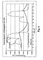
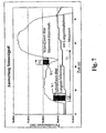
- the capacity is continuously measured by the sensor 3. From the measurements is in the FIGS. 6 and 7 determined long-term average. If the long-term average is exceeded by a predetermined threshold value for a predetermined period, the store is recognized. A purge is triggered as soon as a maximum value falls below a threshold value for a given duration. During rinsing the capacity increases sharply, but then decreases by the emptying and falls below the long-term average. By refilling with blocked water S, the capacity returns to its original value.
- the FIG. 5 shows the course of the field lines 18 and 19 between the electrodes 14 and 16, which are formed as measuring electrodes.
- the field lines 19 extend through lateral walls of the housing 2 and are influenced by deposits and surface water and therefore do not run in a straight line, as is almost the case with the field lines 18.
- With a known guard electrode 17 field lines 19 and any interference fields are largely hidden and therefore not taken into account in the measurement. Therefore, the reliability can be increased even with a long service life even further. The measurement is thus largely based on the undisturbed field.
- FIG. 6 The course of a sensor signal in two subsequent uses of the inventive device 1 is in FIG. 6 shown.
- the measured value increases slightly during use and a corresponding increase in the surface 15 and then drops again, but then rises again sharply to a still higher value after a flushing action.
- flushing the siphon is briefly completely filled with rinse water and correspondingly high capacity. After the water has been sucked off, the fill level drops and then rises again when the bowl is rinsed.
- the course of the long-term average changes accordingly, as the FIG. 6 shows.
- a business is recognized as such when the in FIG. 7 shown threshold value W1 is exceeded over the long-term average for a period of time T1. If the long-term mean is exceeded by a threshold value for a given duration, the store is recognized. If the maximum value falls below a threshold value for a given duration, the flushing is triggered. After flushing a shop, flushing is not triggered until a maximum value has fallen below a threshold value W2 during a predetermined and adjustable period of time T2, or a predetermined time period T3 has elapsed. The triggering of the flushing is thus delayed, for which purpose a corresponding algorithm is provided. If incomplete flushing and therefore the intended level height H is not reached, this is detected by the electronics, since the capacity remains correspondingly small. About the electronics 14 then a final rinse is triggered, which fills the siphon housing 2 accordingly.
Abstract
Description
Die Erfindung betrifft eine Vorrichtung zur selbsttätigen Spülauslösung einer Spülvorrichtung nach dem Oberbegriff des Anspruchs 1.The invention relates to a device for automatically flushing a flushing device according to the preamble of
Die
Die
Die
Die selbsttätige Auslösung einer Spülung bei WC-Anlagen und Urinalen ist seit langem bekannt. Bei einer bekannten Vorrichtung wird mit Radar ein Benutzer festgestellt und eine Spülung ausgelöst, wenn sich dieser entfernt. Es sind auch Vorrichtungen bekannt, bei denen Änderungen im Siphon detektiert und diese zur Auslösung einer Spülung ausgewertet werden.The automatic triggering of a flush in WC systems and urinals has long been known. In a known device, a user is detected by radar and a flushing triggered when it is removed. There are also known devices in which changes in the siphon are detected and these are evaluated to trigger a purge.
So offenbart beispielsweise die
Eine Vorrichtung mit zwei im Inneren des Siphons angeordneten Elektroden ist aus der
Die
Durch die
Es wird vorgeschlagen, die Innenfläche des Siphons im Überlaufbereich wasserabweisend bzw. hydrophob auszubilden, um die genannten Fehlsignale zu vermeiden. Bei längerem Gebrauch lagern sich aber auch bei solchen Oberflächen schliesslich Ablagerungen an, welche das Dielektrikum des Kondensators ändern und Störsignale verursachen.It is proposed to form the inner surface of the siphon in the overflow area water-repellent or hydrophobic in order to avoid the said false signals. With prolonged use, however, even deposits of such surfaces eventually accumulate, which change the dielectric of the capacitor and cause interference signals.
Der Erfindung liegt die Aufgabe zugrunde, eine Vorrichtung und ein Verfahren der genannten Art zu schaffen, welche eine grössere Funktionssicherheit gewährleistet, aber dennoch vergleichsweise kostengünstig realisiert werden kann.The invention has for its object to provide a device and a method of the type mentioned, which ensures greater reliability, but can still be realized comparatively inexpensive.
Die Erfindung ist bei einer gattungsgemässen Vorrichtung gemäss Anspruch 1 gelöst. Bei der erfindungsgemässen Vorrichtung wird nicht eine Kapazitätsänderung infolge einer Benetzung der Innenfläche des Siphons, sondern die Kapazitätsänderung infolge einer Änderung des Wasserstandes im Siphon detektiert und entsprechend eine Spülung ausgelöst. Das Dielektrikum des Kondensators wird wesentlich durch das Sperrwasser und Ablagerungen gebildet. Der Anteil von Oberflächenwasser und Ablagerungen ist vergleichsweise klein.The invention is achieved in a generic device according to
Die Erfindung ermöglicht zudem eine Messung der Füllstandshöhe. Ist beispielsweise ein Siphon nicht bis zur Überlaufkante gefüllt, so kann über den Sensor eine solche unvollständige Füllung detektiert und eine Nachspülung ausgelöst werden. Der kapazitive Sensor misst im Bereich des Sperrwassers und im Luftbereich unmittelbar über dem Niveau des Sperrwassers. Die gemessene Kapazität ist gewissermassen eine Mischrechnung zwischen der Kapazität des Sperrwassers und des darüber liegenden Luftraumes. Verkalkungen an der Innenseite nach der Überlaufkante können die Messung dadurch weniger beeinflussen.The invention also allows a measurement of the level height. If, for example, a siphon is not filled to the overflow edge, then such an incomplete filling can be detected via the sensor and a final rinse can be triggered. The capacitive sensor measures in the area of the sealing water and in the air area immediately above the level of the sealing water. The measured capacity is to a certain extent a mixed calculation between the capacity of the sealing water and the overlying airspace. Calcification on the inside after the overflow edge can affect the measurement less.
Eine noch zuverlässigere Spülauslösung ergibt sich dann, wenn der Sensor eine Guard-Elektrode aufweist, mit welcher Streufelder ausgeblendet werden.An even more reliable rinsing release results when the sensor has a guard electrode with which stray fields are faded out.
Weitere vorteilhafte Merkmale ergeben sich aus den abhängigen Patentansprüchen, der nachfolgenden Beschreibung sowie der Zeichnung.Further advantageous features emerge from the dependent claims, the following description and the drawings.
Ein Ausführungsbeispiel der Erfindung wird nachfolgend anhand der Zeichnung näher erläutert. Es zeigen:
Figur 1- eine Vertikalansicht der erfindungsgemässen Vorrichtung,
Figur 2- eine Ansicht der erfindungsgemässen Vorrichtung,
Figur 3- ein Schnitt entlang der Linie III-III der
Figur 2 - Figur 4
- ein Schnitt durch eine erfindungsgemässe Vorrichtung entlang der Linie IV-IV der
Figur 1 Figur 5- schematisch der Verlauf der Feldlinien zwischen zwei Elektroden,
Figur 6- ein Diagramm mit dem Verlauf des Sensorsignals bei zwei Spülauslösungen und
Figur 7- ein Diagramm zur Illustration der Auswertung der Sensorsignale.
- FIG. 1
- a vertical view of the inventive device,
- FIG. 2
- a view of the inventive device,
- FIG. 3
- a section along the line III-III of
FIG. 2 . - FIG. 4
- a section through an inventive device along the line IV-IV of
FIG. 1 . - FIG. 5
- schematically the course of the field lines between two electrodes,
- FIG. 6
- a diagram with the course of the sensor signal at two flushing trips and
- FIG. 7
- a diagram illustrating the evaluation of the sensor signals.
Die Figuren zeigen eine Vorrichtung 1, die insbesondere einen Urinal-Siphon mit einem Gehäuse 2 aufweist, das aus zwei miteinander verbundenen Gehäusehälften 21 und 22 besteht. An der Gehäusehälfte 21 ist ein Siphoneinlass 6 vorgesehen, in den in Richtung des Pfeiles 9 die abzuführende Flüssigkeit einströmt. Im Gehäuse 2 vorliegendes Sperrwasser S bildet einen Geruchverschluss vor einer Überlaufkante 8. Strömt aus einem hier nicht gezeigten Urinal-Becken Wasser durch den Siphoneinlass 6 in das Gehäuse 2, so steigt die in
Zur selbsttätigen Auslösung einer Spülung ist ein Sensor 3 vorgesehen, der gemäss
Der Sensor 3 weist zwei Elektroden 14 und 16 auf, die gemäss den
Die Kapazität wird vom Sensor 3 laufend gemessen. Aus den Messungen wird der in den
Die
Der Verlauf eines Sensorsignals bei zwei nachfolgenden Benutzungen der erfindungsgemässen Vorrichtung 1 ist in
Ein Geschäft wird als solches erkannt, wenn der in
- 11
- Vorrichtungcontraption
- 22
- Gehäusecasing
- 33
- Sensorsensor
- 44
- Spülvorrichtungflushing
- 55
- Elektronikeinheitelectronics unit
- 66
- SiphoneinlassSiphoneinlass
- 77
- SiphonauslassSiphonauslass
- 88th
- ÜberlaufkanteOverflow edge
- 99
- Pfeilarrow
- 1010
- Pfeilarrow
- 1111
- Pfeilarrow
- 1212
- Pfeilarrow
- 1313
- Pfeilarrow
- 1414
- Elektrodeelectrode
- 14a14a
- Teilpart
- 14b14b
- Teilpart
- 1515
- Oberflächesurface
- 1616
- Elektrodeelectrode
- 1717
- Guardeguarde
- 1818
- Feldlinienfield lines
- 1919
- Feldlinienfield lines
- 2020
- Kanteedge
- 2121
- Gehäusehälftehousing half
- 2222
- Gehäusehälftehousing half
- 2323
- Gehäusecasing
- 2424
- Innenseiteinside
- 2525
- Aussenseiteoutside
- HH
- Füllstandshöhefilling level
- LL
- Luftraumairspace
- SS
- Sperrwassersealing water
- T1T1
- Zeitdauertime
- T2T2
- Zeitdauertime
- T3T3
- Zeitdauertime
- W1W1
- Schwellwertthreshold
- W2W2
- Schwellwertthreshold
Claims (7)
- Device for automatically triggering a flushing device (4), having a siphon (2) which has an inlet (6) and an outlet (7) and also an overflow edge (8) and a channel which rises up to the overflow edge (8), and having means (14, 16) for detecting a rise in the surface (15) of the sealing water (S) in the siphon (2), characterized in that the outside (25) of the siphon (2) has arranged on it a capacitive sensor (3) which has at least one electrode (14, 16) which is arranged upstream of the overflow edge (8), as seen in the flow direction, in the region of the surface (15) of the sealing water (S), the aforementioned surface (15) being located in the channel which rises up to the overflow edge (8).
- Device according to Claim 1, characterized in that changes are determined in the filling-level height (H).
- Device according to Claim 1 or 2, characterized in that the sensor (3) has at least one guard electrode (17) for deflecting interference fields.
- Device according to one of Claims 1 to 3, characterized in that the at least one electrode (14, 16) has a part (14a) which is arranged above the surface (15) of the sealing water (S), and in that a further part (14b) of the at least one electrode (14, 16) is located in the region of the sealing water (S).
- Device according to one of Claims 1 to 4, characterized in that the at least one electrode (14, 16) is arranged on the outside (25) of a siphon housing (2).
- Method of automatically triggering a flushing device, having a siphon (2) with a channel which rises up to an overflow edge (8), and having means (14, 16) for detecting a rise in the surface (15) of the sealing water (S) in the siphon, the rise being evaluated for the purpose of triggering flushing, characterized in that a capacitive sensor (3) is provided on the outside (25) of the siphon (2) and an evaluation electronics unit (16) is provided, and in that changes are determined in the dielectric in the region of the surface (15) of the sealing water (S) upstream of the overflow edge (8), as seen in the flow direction, the aforementioned surface (15) being located in the channel which rises up to the overflow edge (8).
- Method according to Claim 6, characterized in that the capacitance of the sensor (3) is measured continuously and a long-term mean value is determined from the measurements, in that an excretion is detected when, during a predetermined period, the long-term average is exceeded by a predetermined threshold value, and in that flushing is triggered as soon as, during a predetermined period, a measured value falls below a maximum.
Priority Applications (3)
| Application Number | Priority Date | Filing Date | Title |
|---|---|---|---|
| EP04405231A EP1586713B1 (en) | 2004-04-15 | 2004-04-15 | Device and method for automatic iniciation of flushing of a flushing device using a capacitive sensor |
| DE502004010488T DE502004010488D1 (en) | 2004-04-15 | 2004-04-15 | Device and method for autonomous Spülauslösung a flushing device by means of a capacitive sensor |
| AT04405231T ATE451506T1 (en) | 2004-04-15 | 2004-04-15 | DEVICE AND METHOD FOR INDEPENDENTLY TRIGGERING A FLUSHING DEVICE USING A CAPACITIVE SENSOR |
Applications Claiming Priority (1)
| Application Number | Priority Date | Filing Date | Title |
|---|---|---|---|
| EP04405231A EP1586713B1 (en) | 2004-04-15 | 2004-04-15 | Device and method for automatic iniciation of flushing of a flushing device using a capacitive sensor |
Publications (2)
| Publication Number | Publication Date |
|---|---|
| EP1586713A1 EP1586713A1 (en) | 2005-10-19 |
| EP1586713B1 true EP1586713B1 (en) | 2009-12-09 |
Family
ID=34932058
Family Applications (1)
| Application Number | Title | Priority Date | Filing Date |
|---|---|---|---|
| EP04405231A Expired - Lifetime EP1586713B1 (en) | 2004-04-15 | 2004-04-15 | Device and method for automatic iniciation of flushing of a flushing device using a capacitive sensor |
Country Status (3)
| Country | Link |
|---|---|
| EP (1) | EP1586713B1 (en) |
| AT (1) | ATE451506T1 (en) |
| DE (1) | DE502004010488D1 (en) |
Cited By (1)
| Publication number | Priority date | Publication date | Assignee | Title |
|---|---|---|---|---|
| US9328490B2 (en) | 2006-10-24 | 2016-05-03 | Bradley Fixtures Corporation | Capacitive sensing for washroom fixture |
Families Citing this family (5)
| Publication number | Priority date | Publication date | Assignee | Title |
|---|---|---|---|---|
| EP2076635B1 (en) * | 2006-08-07 | 2009-12-30 | Kotte GmbH & Co. KG | Method and apparatus for detecting the use of urinals and for initiating automatic flushing |
| CN101230592B (en) * | 2007-12-27 | 2011-04-27 | 上海科勒电子科技有限公司 | Auto-induction urinating bucket |
| DE202010002565U1 (en) * | 2010-02-19 | 2010-05-27 | Sanitärtechnik Eisenberg GmbH | suction siphon |
| EP3521524A1 (en) * | 2018-02-06 | 2019-08-07 | IPee N.V. | Sanitary appliance comprising a sensor circuit and use thereof |
| DE102019125370A1 (en) | 2019-09-20 | 2021-03-25 | Caroma Industries Limited | Urinal system, water consumer system with a urinal system and method for operating a urinal system |
Family Cites Families (5)
| Publication number | Priority date | Publication date | Assignee | Title |
|---|---|---|---|---|
| US669037A (en) * | 1898-11-03 | 1901-02-26 | John Walter Stevens | Automatic flushing-tank. |
| DE3228061A1 (en) * | 1981-07-28 | 1983-02-17 | Bieri Pumpenbau AG, 3110 Münsingen, Bern | Device for actuating the flushing of a WC installation |
| DE10006670A1 (en) * | 1999-12-22 | 2001-07-05 | Friatec Ag | Method for disposing of flush water from toilet basins has an overflow sensing electrode positioned at the top of the syphon |
| WO2002050498A1 (en) * | 2000-12-20 | 2002-06-27 | Abertax Research And Development Ltd. | Method and device for measuring levels |
| DE10111210B4 (en) * | 2001-03-08 | 2005-05-12 | Mepa-Pauli Und Menden Gmbh | Method for controlling the flushing of a urinal |
-
2004
- 2004-04-15 DE DE502004010488T patent/DE502004010488D1/en not_active Expired - Lifetime
- 2004-04-15 AT AT04405231T patent/ATE451506T1/en active
- 2004-04-15 EP EP04405231A patent/EP1586713B1/en not_active Expired - Lifetime
Cited By (1)
| Publication number | Priority date | Publication date | Assignee | Title |
|---|---|---|---|---|
| US9328490B2 (en) | 2006-10-24 | 2016-05-03 | Bradley Fixtures Corporation | Capacitive sensing for washroom fixture |
Also Published As
| Publication number | Publication date |
|---|---|
| EP1586713A1 (en) | 2005-10-19 |
| ATE451506T1 (en) | 2009-12-15 |
| DE502004010488D1 (en) | 2010-01-21 |
Similar Documents
| Publication | Publication Date | Title |
|---|---|---|
| EP3335611B1 (en) | Floor cleaning machine with fill level measurement for dirty fluid tank | |
| EP3418457A1 (en) | Monitoring system for monitoring a water level in a sanitary element and a sanitary element | |
| CH663045A5 (en) | DRAIN SET FOR A CLEANER. | |
| EP2076635B1 (en) | Method and apparatus for detecting the use of urinals and for initiating automatic flushing | |
| DE102005018879A1 (en) | Dishwasher has pushing element being lifted by floater to turn on switch and prevent oversupply of water into the sump | |
| EP1586713B1 (en) | Device and method for automatic iniciation of flushing of a flushing device using a capacitive sensor | |
| AT4952U1 (en) | CLEANING BOX FOR A CLEANING SYSTEM AND METHOD FOR ACTUATING SUCH A CLEANING BOX | |
| EP4089240A2 (en) | Toilet flushing module and toilet | |
| EP2090701A1 (en) | Urinal with mechanical odour seal | |
| DE102011011624A1 (en) | Water supply device for sanitary installation e.g. toilet with integrated shower function, has pump that is connected to outlet port connected to water carrying line of sanitary installation, via which pump pumps the water from tank | |
| DE102004006973A1 (en) | Steam cooking appliance for operating with a controlled volume flow of fresh water has a fresh water supply pipe | |
| EP0353183A1 (en) | Radar sonde for the automatic individual control of sanitary fittings | |
| DE4202245A1 (en) | DEVICE FOR BRANCHING RAINWATER FROM A GUTTER PIPE | |
| DE102020108234A1 (en) | Sanitary facility | |
| DE60124980T2 (en) | Apparatus for flushing a toilet bowl or the like | |
| WO2016026709A1 (en) | Flushing device | |
| DE102004029567B4 (en) | Dust control cell | |
| DE202017007227U1 (en) | Hygiene station | |
| AT9518U1 (en) | METHOD FOR CONTROLLING THE FLUSHING OF A FLUSH SINK AND REDUCING WATER CONSUMPTION | |
| DE202017007225U1 (en) | Hygiene station | |
| DE102011013696A1 (en) | Discharging device i.e. floor drain, for discharging residual water from barrier-free shower of old building, has control unit for simulating amount of effluent in drain body in mounted state of device | |
| DE202007015077U1 (en) | Siphon for sanitary flushing systems, in particular for urinals | |
| EP3219864B1 (en) | Liquid recipient with valve and corresponding method of use producing a rinsing surge | |
| DE3123501A1 (en) | System for functionally extending conventional WC cisterns | |
| DE2445223A1 (en) | Flushing water valve system for urinals - has liquid level actuated electronic circuit for flushing solenoid valve |
Legal Events
| Date | Code | Title | Description |
|---|---|---|---|
| PUAI | Public reference made under article 153(3) epc to a published international application that has entered the european phase |
Free format text: ORIGINAL CODE: 0009012 |
|
| AK | Designated contracting states |
Kind code of ref document: A1 Designated state(s): AT BE BG CH CY CZ DE DK EE ES FI FR GB GR HU IE IT LI LU MC NL PL PT RO SE SI SK TR |
|
| AX | Request for extension of the european patent |
Extension state: AL HR LT LV MK |
|
| 17P | Request for examination filed |
Effective date: 20060304 |
|
| AKX | Designation fees paid |
Designated state(s): AT BE BG CH CY CZ DE DK EE ES FI FR GB GR HU IE IT LI LU MC NL PL PT RO SE SI SK TR |
|
| 17Q | First examination report despatched |
Effective date: 20060606 |
|
| APBN | Date of receipt of notice of appeal recorded |
Free format text: ORIGINAL CODE: EPIDOSNNOA2E |
|
| APBR | Date of receipt of statement of grounds of appeal recorded |
Free format text: ORIGINAL CODE: EPIDOSNNOA3E |
|
| APAF | Appeal reference modified |
Free format text: ORIGINAL CODE: EPIDOSCREFNE |
|
| APAI | Date of receipt of notice of appeal modified |
Free format text: ORIGINAL CODE: EPIDOSCNOA2E |
|
| APAK | Date of receipt of statement of grounds of an appeal modified |
Free format text: ORIGINAL CODE: EPIDOSCNOA3E |
|
| APBT | Appeal procedure closed |
Free format text: ORIGINAL CODE: EPIDOSNNOA9E |
|
| GRAP | Despatch of communication of intention to grant a patent |
Free format text: ORIGINAL CODE: EPIDOSNIGR1 |
|
| GRAS | Grant fee paid |
Free format text: ORIGINAL CODE: EPIDOSNIGR3 |
|
| GRAA | (expected) grant |
Free format text: ORIGINAL CODE: 0009210 |
|
| RAP1 | Party data changed (applicant data changed or rights of an application transferred) |
Owner name: GEBERIT INTERNATIONAL AG |
|
| AK | Designated contracting states |
Kind code of ref document: B1 Designated state(s): AT BE BG CH CY CZ DE DK EE ES FI FR GB GR HU IE IT LI LU MC NL PL PT RO SE SI SK TR |
|
| REG | Reference to a national code |
Ref country code: GB Ref legal event code: FG4D Free format text: NOT ENGLISH |
|
| REG | Reference to a national code |
Ref country code: CH Ref legal event code: EP Ref country code: CH Ref legal event code: NV Representative=s name: ISLER & PEDRAZZINI AG |
|
| REG | Reference to a national code |
Ref country code: IE Ref legal event code: FG4D |
|
| REF | Corresponds to: |
Ref document number: 502004010488 Country of ref document: DE Date of ref document: 20100121 Kind code of ref document: P |
|
| REG | Reference to a national code |
Ref country code: NL Ref legal event code: VDEP Effective date: 20091209 |
|
| PG25 | Lapsed in a contracting state [announced via postgrant information from national office to epo] |
Ref country code: FI Free format text: LAPSE BECAUSE OF FAILURE TO SUBMIT A TRANSLATION OF THE DESCRIPTION OR TO PAY THE FEE WITHIN THE PRESCRIBED TIME-LIMIT Effective date: 20091209 Ref country code: SE Free format text: LAPSE BECAUSE OF FAILURE TO SUBMIT A TRANSLATION OF THE DESCRIPTION OR TO PAY THE FEE WITHIN THE PRESCRIBED TIME-LIMIT Effective date: 20091209 |
|
| PG25 | Lapsed in a contracting state [announced via postgrant information from national office to epo] |
Ref country code: PL Free format text: LAPSE BECAUSE OF FAILURE TO SUBMIT A TRANSLATION OF THE DESCRIPTION OR TO PAY THE FEE WITHIN THE PRESCRIBED TIME-LIMIT Effective date: 20091209 Ref country code: SI Free format text: LAPSE BECAUSE OF FAILURE TO SUBMIT A TRANSLATION OF THE DESCRIPTION OR TO PAY THE FEE WITHIN THE PRESCRIBED TIME-LIMIT Effective date: 20091209 |
|
| REG | Reference to a national code |
Ref country code: IE Ref legal event code: FD4D |
|
| PG25 | Lapsed in a contracting state [announced via postgrant information from national office to epo] |
Ref country code: PT Free format text: LAPSE BECAUSE OF FAILURE TO SUBMIT A TRANSLATION OF THE DESCRIPTION OR TO PAY THE FEE WITHIN THE PRESCRIBED TIME-LIMIT Effective date: 20100409 Ref country code: RO Free format text: LAPSE BECAUSE OF FAILURE TO SUBMIT A TRANSLATION OF THE DESCRIPTION OR TO PAY THE FEE WITHIN THE PRESCRIBED TIME-LIMIT Effective date: 20091209 Ref country code: NL Free format text: LAPSE BECAUSE OF FAILURE TO SUBMIT A TRANSLATION OF THE DESCRIPTION OR TO PAY THE FEE WITHIN THE PRESCRIBED TIME-LIMIT Effective date: 20091209 Ref country code: BG Free format text: LAPSE BECAUSE OF FAILURE TO SUBMIT A TRANSLATION OF THE DESCRIPTION OR TO PAY THE FEE WITHIN THE PRESCRIBED TIME-LIMIT Effective date: 20100309 Ref country code: EE Free format text: LAPSE BECAUSE OF FAILURE TO SUBMIT A TRANSLATION OF THE DESCRIPTION OR TO PAY THE FEE WITHIN THE PRESCRIBED TIME-LIMIT Effective date: 20091209 Ref country code: ES Free format text: LAPSE BECAUSE OF FAILURE TO SUBMIT A TRANSLATION OF THE DESCRIPTION OR TO PAY THE FEE WITHIN THE PRESCRIBED TIME-LIMIT Effective date: 20100320 Ref country code: IE Free format text: LAPSE BECAUSE OF FAILURE TO SUBMIT A TRANSLATION OF THE DESCRIPTION OR TO PAY THE FEE WITHIN THE PRESCRIBED TIME-LIMIT Effective date: 20091209 |
|
| PG25 | Lapsed in a contracting state [announced via postgrant information from national office to epo] |
Ref country code: CZ Free format text: LAPSE BECAUSE OF FAILURE TO SUBMIT A TRANSLATION OF THE DESCRIPTION OR TO PAY THE FEE WITHIN THE PRESCRIBED TIME-LIMIT Effective date: 20091209 Ref country code: SK Free format text: LAPSE BECAUSE OF FAILURE TO SUBMIT A TRANSLATION OF THE DESCRIPTION OR TO PAY THE FEE WITHIN THE PRESCRIBED TIME-LIMIT Effective date: 20091209 |
|
| PLBE | No opposition filed within time limit |
Free format text: ORIGINAL CODE: 0009261 |
|
| STAA | Information on the status of an ep patent application or granted ep patent |
Free format text: STATUS: NO OPPOSITION FILED WITHIN TIME LIMIT |
|
| PG25 | Lapsed in a contracting state [announced via postgrant information from national office to epo] |
Ref country code: GR Free format text: LAPSE BECAUSE OF FAILURE TO SUBMIT A TRANSLATION OF THE DESCRIPTION OR TO PAY THE FEE WITHIN THE PRESCRIBED TIME-LIMIT Effective date: 20100310 Ref country code: CY Free format text: LAPSE BECAUSE OF FAILURE TO SUBMIT A TRANSLATION OF THE DESCRIPTION OR TO PAY THE FEE WITHIN THE PRESCRIBED TIME-LIMIT Effective date: 20091209 |
|
| BERE | Be: lapsed |
Owner name: GEBERIT INTERNATIONAL A.G. Effective date: 20100430 |
|
| 26N | No opposition filed |
Effective date: 20100910 |
|
| PG25 | Lapsed in a contracting state [announced via postgrant information from national office to epo] |
Ref country code: MC Free format text: LAPSE BECAUSE OF NON-PAYMENT OF DUE FEES Effective date: 20100430 |
|
| GBPC | Gb: european patent ceased through non-payment of renewal fee |
Effective date: 20100415 |
|
| REG | Reference to a national code |
Ref country code: FR Ref legal event code: ST Effective date: 20101230 |
|
| PG25 | Lapsed in a contracting state [announced via postgrant information from national office to epo] |
Ref country code: DK Free format text: LAPSE BECAUSE OF FAILURE TO SUBMIT A TRANSLATION OF THE DESCRIPTION OR TO PAY THE FEE WITHIN THE PRESCRIBED TIME-LIMIT Effective date: 20091209 |
|
| PG25 | Lapsed in a contracting state [announced via postgrant information from national office to epo] |
Ref country code: BE Free format text: LAPSE BECAUSE OF NON-PAYMENT OF DUE FEES Effective date: 20100430 Ref country code: GB Free format text: LAPSE BECAUSE OF NON-PAYMENT OF DUE FEES Effective date: 20100415 Ref country code: IT Free format text: LAPSE BECAUSE OF FAILURE TO SUBMIT A TRANSLATION OF THE DESCRIPTION OR TO PAY THE FEE WITHIN THE PRESCRIBED TIME-LIMIT Effective date: 20091209 |
|
| PG25 | Lapsed in a contracting state [announced via postgrant information from national office to epo] |
Ref country code: FR Free format text: LAPSE BECAUSE OF NON-PAYMENT OF DUE FEES Effective date: 20100430 |
|
| PGFP | Annual fee paid to national office [announced via postgrant information from national office to epo] |
Ref country code: CH Payment date: 20120419 Year of fee payment: 9 |
|
| PG25 | Lapsed in a contracting state [announced via postgrant information from national office to epo] |
Ref country code: LU Free format text: LAPSE BECAUSE OF NON-PAYMENT OF DUE FEES Effective date: 20100415 Ref country code: HU Free format text: LAPSE BECAUSE OF FAILURE TO SUBMIT A TRANSLATION OF THE DESCRIPTION OR TO PAY THE FEE WITHIN THE PRESCRIBED TIME-LIMIT Effective date: 20100610 |
|
| PG25 | Lapsed in a contracting state [announced via postgrant information from national office to epo] |
Ref country code: TR Free format text: LAPSE BECAUSE OF FAILURE TO SUBMIT A TRANSLATION OF THE DESCRIPTION OR TO PAY THE FEE WITHIN THE PRESCRIBED TIME-LIMIT Effective date: 20091209 |
|
| PGFP | Annual fee paid to national office [announced via postgrant information from national office to epo] |
Ref country code: AT Payment date: 20120411 Year of fee payment: 9 |
|
| REG | Reference to a national code |
Ref country code: DE Ref legal event code: R082 Ref document number: 502004010488 Country of ref document: DE Representative=s name: HOEGER, STELLRECHT & PARTNER PATENTANWAELTE, DE Ref country code: DE Ref legal event code: R082 Ref document number: 502004010488 Country of ref document: DE Representative=s name: HOEGER, STELLRECHT & PARTNER PATENTANWAELTE MB, DE |
|
| REG | Reference to a national code |
Ref country code: CH Ref legal event code: PL |
|
| REG | Reference to a national code |
Ref country code: AT Ref legal event code: MM01 Ref document number: 451506 Country of ref document: AT Kind code of ref document: T Effective date: 20130430 |
|
| PG25 | Lapsed in a contracting state [announced via postgrant information from national office to epo] |
Ref country code: CH Free format text: LAPSE BECAUSE OF NON-PAYMENT OF DUE FEES Effective date: 20130430 Ref country code: AT Free format text: LAPSE BECAUSE OF NON-PAYMENT OF DUE FEES Effective date: 20130430 Ref country code: LI Free format text: LAPSE BECAUSE OF NON-PAYMENT OF DUE FEES Effective date: 20130430 |
|
| REG | Reference to a national code |
Ref country code: DE Ref legal event code: R082 Ref document number: 502004010488 Country of ref document: DE Representative=s name: HOEGER, STELLRECHT & PARTNER PATENTANWAELTE MB, DE |
|
| PGFP | Annual fee paid to national office [announced via postgrant information from national office to epo] |
Ref country code: DE Payment date: 20160421 Year of fee payment: 13 |
|
| REG | Reference to a national code |
Ref country code: DE Ref legal event code: R119 Ref document number: 502004010488 Country of ref document: DE |
|
| PG25 | Lapsed in a contracting state [announced via postgrant information from national office to epo] |
Ref country code: DE Free format text: LAPSE BECAUSE OF NON-PAYMENT OF DUE FEES Effective date: 20171103 |