EP1586482A1 - Seat device for a vehicle and vehicle provided therewith - Google Patents
Seat device for a vehicle and vehicle provided therewith Download PDFInfo
- Publication number
- EP1586482A1 EP1586482A1 EP05005602A EP05005602A EP1586482A1 EP 1586482 A1 EP1586482 A1 EP 1586482A1 EP 05005602 A EP05005602 A EP 05005602A EP 05005602 A EP05005602 A EP 05005602A EP 1586482 A1 EP1586482 A1 EP 1586482A1
- Authority
- EP
- European Patent Office
- Prior art keywords
- seat
- vehicle
- cushion
- folded
- see
- Prior art date
- Legal status (The legal status is an assumption and is not a legal conclusion. Google has not performed a legal analysis and makes no representation as to the accuracy of the status listed.)
- Granted
Links
Images


Classifications
-
- B—PERFORMING OPERATIONS; TRANSPORTING
- B60—VEHICLES IN GENERAL
- B60N—SEATS SPECIALLY ADAPTED FOR VEHICLES; VEHICLE PASSENGER ACCOMMODATION NOT OTHERWISE PROVIDED FOR
- B60N2/00—Seats specially adapted for vehicles; Arrangement or mounting of seats in vehicles
- B60N2/02—Seats specially adapted for vehicles; Arrangement or mounting of seats in vehicles the seat or part thereof being movable, e.g. adjustable
- B60N2/04—Seats specially adapted for vehicles; Arrangement or mounting of seats in vehicles the seat or part thereof being movable, e.g. adjustable the whole seat being movable
- B60N2/06—Seats specially adapted for vehicles; Arrangement or mounting of seats in vehicles the seat or part thereof being movable, e.g. adjustable the whole seat being movable slidable
- B60N2/062—Seats specially adapted for vehicles; Arrangement or mounting of seats in vehicles the seat or part thereof being movable, e.g. adjustable the whole seat being movable slidable transversally slidable
-
- B—PERFORMING OPERATIONS; TRANSPORTING
- B60—VEHICLES IN GENERAL
- B60N—SEATS SPECIALLY ADAPTED FOR VEHICLES; VEHICLE PASSENGER ACCOMMODATION NOT OTHERWISE PROVIDED FOR
- B60N2/00—Seats specially adapted for vehicles; Arrangement or mounting of seats in vehicles
- B60N2/02—Seats specially adapted for vehicles; Arrangement or mounting of seats in vehicles the seat or part thereof being movable, e.g. adjustable
- B60N2/04—Seats specially adapted for vehicles; Arrangement or mounting of seats in vehicles the seat or part thereof being movable, e.g. adjustable the whole seat being movable
- B60N2/06—Seats specially adapted for vehicles; Arrangement or mounting of seats in vehicles the seat or part thereof being movable, e.g. adjustable the whole seat being movable slidable
- B60N2/065—Rear seats
-
- B—PERFORMING OPERATIONS; TRANSPORTING
- B60—VEHICLES IN GENERAL
- B60N—SEATS SPECIALLY ADAPTED FOR VEHICLES; VEHICLE PASSENGER ACCOMMODATION NOT OTHERWISE PROVIDED FOR
- B60N2/00—Seats specially adapted for vehicles; Arrangement or mounting of seats in vehicles
- B60N2/24—Seats specially adapted for vehicles; Arrangement or mounting of seats in vehicles for particular purposes or particular vehicles
- B60N2/26—Seats specially adapted for vehicles; Arrangement or mounting of seats in vehicles for particular purposes or particular vehicles for children
- B60N2/28—Seats readily mountable on, and dismountable from, existing seats or other parts of the vehicle
-
- B—PERFORMING OPERATIONS; TRANSPORTING
- B60—VEHICLES IN GENERAL
- B60N—SEATS SPECIALLY ADAPTED FOR VEHICLES; VEHICLE PASSENGER ACCOMMODATION NOT OTHERWISE PROVIDED FOR
- B60N2/00—Seats specially adapted for vehicles; Arrangement or mounting of seats in vehicles
- B60N2/24—Seats specially adapted for vehicles; Arrangement or mounting of seats in vehicles for particular purposes or particular vehicles
- B60N2/30—Non-dismountable or dismountable seats storable in a non-use position, e.g. foldable spare seats
- B60N2/3002—Non-dismountable or dismountable seats storable in a non-use position, e.g. foldable spare seats back-rest movements
- B60N2/3004—Non-dismountable or dismountable seats storable in a non-use position, e.g. foldable spare seats back-rest movements by rotation only
- B60N2/3009—Non-dismountable or dismountable seats storable in a non-use position, e.g. foldable spare seats back-rest movements by rotation only about transversal axis
- B60N2/3011—Non-dismountable or dismountable seats storable in a non-use position, e.g. foldable spare seats back-rest movements by rotation only about transversal axis the back-rest being hinged on the cushion, e.g. "portefeuille movement"
-
- B—PERFORMING OPERATIONS; TRANSPORTING
- B60—VEHICLES IN GENERAL
- B60N—SEATS SPECIALLY ADAPTED FOR VEHICLES; VEHICLE PASSENGER ACCOMMODATION NOT OTHERWISE PROVIDED FOR
- B60N2/00—Seats specially adapted for vehicles; Arrangement or mounting of seats in vehicles
- B60N2/24—Seats specially adapted for vehicles; Arrangement or mounting of seats in vehicles for particular purposes or particular vehicles
- B60N2/30—Non-dismountable or dismountable seats storable in a non-use position, e.g. foldable spare seats
- B60N2/3038—Cushion movements
- B60N2/304—Cushion movements by rotation only
- B60N2/3045—Cushion movements by rotation only about transversal axis
- B60N2/305—Cushion movements by rotation only about transversal axis the cushion being hinged on the vehicle frame
-
- B—PERFORMING OPERATIONS; TRANSPORTING
- B60—VEHICLES IN GENERAL
- B60N—SEATS SPECIALLY ADAPTED FOR VEHICLES; VEHICLE PASSENGER ACCOMMODATION NOT OTHERWISE PROVIDED FOR
- B60N2/00—Seats specially adapted for vehicles; Arrangement or mounting of seats in vehicles
- B60N2/24—Seats specially adapted for vehicles; Arrangement or mounting of seats in vehicles for particular purposes or particular vehicles
- B60N2/30—Non-dismountable or dismountable seats storable in a non-use position, e.g. foldable spare seats
- B60N2/3038—Cushion movements
- B60N2/3063—Cushion movements by composed movement
- B60N2/3065—Cushion movements by composed movement in a longitudinal-vertical plane
-
- B—PERFORMING OPERATIONS; TRANSPORTING
- B60—VEHICLES IN GENERAL
- B60N—SEATS SPECIALLY ADAPTED FOR VEHICLES; VEHICLE PASSENGER ACCOMMODATION NOT OTHERWISE PROVIDED FOR
- B60N2/00—Seats specially adapted for vehicles; Arrangement or mounting of seats in vehicles
- B60N2/24—Seats specially adapted for vehicles; Arrangement or mounting of seats in vehicles for particular purposes or particular vehicles
- B60N2/30—Non-dismountable or dismountable seats storable in a non-use position, e.g. foldable spare seats
- B60N2/3088—Non-dismountable or dismountable seats storable in a non-use position, e.g. foldable spare seats characterised by the mechanical link
- B60N2/309—Non-dismountable or dismountable seats storable in a non-use position, e.g. foldable spare seats characterised by the mechanical link rods
-
- B—PERFORMING OPERATIONS; TRANSPORTING
- B60—VEHICLES IN GENERAL
- B60N—SEATS SPECIALLY ADAPTED FOR VEHICLES; VEHICLE PASSENGER ACCOMMODATION NOT OTHERWISE PROVIDED FOR
- B60N2205/00—General mechanical or structural details
- B60N2205/30—Seat or seat parts characterised by comprising plural parts or pieces
- B60N2205/35—Seat, bench or back-rests being split laterally in two or more parts
Definitions
- the present invention relates to a seat device for a vehicle, such as a rear seat, which is or is to be disposed on a floor panel in a cabin equipped with an ingress and egress opening at a side, and to a vehicle equipped with such a seat device.
- Japanese Patent Laid-Open Publication No. 2000-264109 discloses a rear seat device for a vehicle, in which a center seat is disposed between a right seat and a left seat and these right and left seats are moved back to a position between a pair of wheel houses, by moving the center seat forward and then moving the right and left seats back obliquely in such a manner that the right and left seats approach to each other.
- the above-described seat device has an advantage that it can improve comfortable sitting of the rear passenger on the seat, by moving back the right and left seats to the position between the wheel houses. It has a problem, however, that it could not provide a storage space beside the seat to allow an easy loading (easy access) from the outside of the vehicle.
- the present invention has been devised in view of the above-described problem, and an object of the invention to provide a seat device for a vehicle which can provide a storage space properly beside the seat to allow an easy loading (easy access) from the outside of the vehicle, thereby improving facilities of the vehicle.
- a seat device for a vehicle which is or is to be disposed on a floor panel in a cabin equipped with an ingress and egress opening at a side, comprising a first seat being provided so as to be at least partly folded, a second seat being provided beside the first seat, and a second-seat moving mechanism to move the second seat substantially laterally (i.e. in a direction intersecting the vehicle longitudinal direction) at least partly into a space at or toward an original existing location of the first seat before the first seat has been folded.
- the first seat and the second seat may constitute a rear seat of the vehicle which comprises right and left split seats.
- the second seat can be moved substantially laterally into the space at the original existing location of the first seat before the first seat has been at least partly folded, there can be provided the proper storage space beside the seat to allow the easy loading and easy access to this storage space from the outside of the vehicle through the ingress and egress opening formed at the side, thereby improving facilities and operability of the vehicle.
- the first seat comprises a seat cushion and a seat back
- the seat back is configured so as to be at least partly folded towards or on the seat cushion
- a first-seat holding mechanism to hold the first seat with the seat cushion and the seat back folded on the seat cushion in a double-fold state where both the seat cushion and seat back are positioned in a substantially upright position.
- the holding mechanism holds the first seat in the double-fold state where the seat cushion and seat back folded on the seat cushion have been rotated forward together.
- the space for the second seat being moved into can be at least partly provided properly just behind the first seat.
- the first seat comprises a headrest mounted to the seat back, said first seat being arrangeable in said double-fold state with the headrest mounted to the seat back.
- operability is further improved.
- the first seat is configured so as to have a smaller width than the second seat. According to this structure, since the first seat having the smaller width is light compared with the second seat having the larger width, it is easy to operate. Also, since the second seat with the larger width is moved laterally for the use, the comfortable sitting of the passenger on it can be improved.
- the second seat comprises a seat cushion and a seat back
- the seat back of the second seat is configured so as to be at least partly folded towards or on the seat cushion of the second seat
- a second-seat holding mechanism to hold the second seat with the seat cushion and the seat back folded towards or on the seat cushion in a double-fold state where both the seat cushion and seat back of the second seat are positioned in a substantially upright position.
- a storage space is formed between the second seat and a side wall of the cabin. According to this structure, since there can be the storage space (loading space) between the second seat and the side wall of the cabin, the easy loading and easy access from the outside of the vehicle can be attained.
- a slide mechanism to move the second seat substantially backward (i.e. with a movement component in the vehicle longitudinal direction) to a position at least partly between wheel houses which project inwardly respectively in the cabin.
- the second-seat moving mechanism comprise one or more seat slide rails which are to be attached at or to the floor panel, preferably a difference-in-level portion of the floor panel.
- a vehicle comprising a seat device according to the invention or a preferred embodiment thereof, which is disposed on a floor panel in a cabin or passenger compartment equipped with an ingress and egress opening at a side.
- FIG. 1 is a plan view of a vehicle equipped with a seat device for a vehicle according to the present invention.
- FIG. 2 is a perspective view of a major portion of FIG. 1.
- FIG. 3 is an enlarged plan view of the major portion of FIG. 1.
- FIG. 4 is a view seen along line A-A of FIG. 3.
- FIG. 5 is a view seen along line B-B of FIG. 3.
- FIG. 6 is a perspective view illustrating a seat support structure.
- FIG. 7 is a perspective view illustrating a double-fold state of a first seat.
- FIG. 8 is a plan view of a major portion of FIG. 7.
- FIG. 9 is a side view of the major portion of FIG. 7.
- FIG. 10 is a plan view illustrating a lateral movement of a second seat.
- FIG. 11 is a perspective view illustrating an exemplified seat-use state.
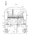
- FIG. 12 is a plan view illustrating another embodiment of the seat device for a vehicle.
- FIG. 13 is a view seen along line C-C of FIG. 12.
- FIG. 14 is a view seen along line D-D of FIG. 12.
- FIG. 15 is a perspective view illustrating a seat support structure.
- FIG. 16 is a plan view illustrating a double-fold state of a first seat.
- FIG. 17 is a side view of FIG. 16.
- FIG. 18 is a plan view illustrating a lateral movement of a second seat.
- FIG. 19 is a perspective view of the seat having the lateral movement.
- FIG. 20 is a plan view illustrating the second seat which is located between wheel houses.
- FIG. 21 is a side view of FIG. 20.
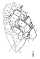
- FIG. 22 is a perspective view illustrating both seats in double-fold state.
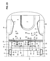
- FIG. 23 is an enlarged plan view of a major portion of FIG. 22.
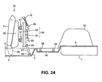
- FIG. 24 is a side view of the major portion of FIG. 22.
- FIG. 25 is a side view illustrating another support structure of a lower portion of a lower-rail extending end.
- FIG. 1 There is provided a dash lower panel (dash panel) 3 which separates a cabin or passenger compartment 2 from an engine room 1 longitudinally.
- a floor panel 4 is connected to a lower end of the dash panel 3 so as to extend rearward substantially horizontally.
- a rear floor 6 is connected to a rear portion of the floor panel 4 via a kickup or slant portion 5.
- a spare tire pan 7 At an intermediate portion (preferably substantially a central portion) of the rear floor 6 in a vehicle width direction is formed a spare tire pan 7. And, at both sides of the floor 4 are fixed side sills 8, 8, as vehicle-body rigidity members extending substantially longitudinally.
- the side sill 8 comprises a side sill inner, a side sill reinforcement and a side sill outer, which form a side sill substantially closed section.
- the tunnel portion 9 is formed so as to extend substantially longitudinally between the dash lower panel 3 and the kickup portion 5.
- a cross member 10 (so-called a NO. 2 cross member), as a preferred vehicle-body rigidity member, which extends substantially in the vehicle width direction to the both side sills 8, 8 beyond the above-described tunnel portion 9.
- a pair of lateral or right-and-left cross members 11, 11 (so-called No. 2.5 cross members) in back of the cross member 10 which extends substantially perpendicularly to the tunnel portion 9 so as to interconnect the tunnel portion 9 and the side sill 8, respectively.
- a pair of front side frames 13, 13 (front frames) as preferred vehicle-body rigidity members is provided at or near both sides in the engine room 1, in which an engine 12 is located, so as to extend substantially longitudinally.
- front side frames 13, 13 At rear ends of the front side frames 13, 13 are continuously connected floor frames (not illustrated), as preferred vehicle-body rigidity members, which are fixed at a lower face of the floor panel 4.
- one or more, e.g. two right-and-left front seats 14, 14 are or are to be (directly or indirectly) attached on or to the respective cross members 10, 11.
- Each front seat 14 comprises a seat cushion 15, a seat back 16 and a headrest 17.
- One of the front seats 14, 14 is provided as a driver's seat and the other one 14 is provided as a passenger's seat.
- a rear seat 30 is or is to be (directly or indirectly) attached on or to the rear floor 6 near the kickup portion 5 behind the front seats 14, 14.
- Reference numerals 19, 19 denote front wheels of the vehicle and reference numerals 20, 20 denote rear wheels of the vehicle in FIG. 1.
- FIGS. 2 through 6 there is preferably provided a center pillar or B post 21 extending substantially vertically between the side sill 8 and a roof side. And, an ingress and egress opening 23 for a rear passenger is formed in back of the center pillar 21, more specifically between the center pillar 21 and a quarter pillar or C post 22 (see FIG. 2 ) .
- the center pillar 21 is a preferred vehicle-body rigidity member, comprising a center pillar outer 24 and a center pillar inner 25, which form a pillar substantially closed section 26 extending substantially vertically.
- the above-described rear seat 30 is provided on or at the rear floor 6 in the cabin 2 equipped with the ingress and egress opening 23 at the side, and the rear seat 30 comprises a left seat 31 (a first seat) and a right seat 32 (a second seat) which are split in the vehicle width direction.
- the left seat 31 preferably is configured so as to have a smaller width than the right seat 32 and comprise a seat cushion 33, a seat back 34 and a headrest 35.
- the right seat 32 preferably is configured so as to have a larger width than the left seat 31 and comprise a seat cushion 36, a seat back 37 and a headrest 38.
- At least a pair of right-and-left hinge brackets 40, 40 and a latch 41 are provided at a lower portion of the seat cushion 33 of the left seat 31. Further, at the kickup portion 5 are attached different hinge brackets 42, 42 so as to correspond to the above-described hinge brackets 40, 40. And, at least a pair of link members 43, 43 interconnects the respective hinge brackets 40 and 42. Further, a striker or abutment 44 is fixed to a difference-in-level portion 6a of the rear floor 6 so as to substantially correspond to the above-described latch 41. The striker 44 and the latch 41 constitute a lock member 45. At the latch 41 is attached a release strap or bar 46 (see FIG. 4 ) as a preferred release member to disengage the latch 41 from the striker 44.
- the seat back 34 of the left seat 31 is supported so as to rotate or pivot forward and rearward (reclining) around a reclining pivot 47 at a reclining knuckle with respect to the seat cushion 33.
- the left seat 31 can be changed to its double-fold state DFS through the following operational steps. Namely, first, the latch 41 is disengaged from the striker 44 by operating the release strap 46. Then, the seat back 34 is rotated or pivoted forward around the reclining pivot 47 to be at least partly folded on or rotated or pivoted towards the seat cushion 33. Next, the seat cushion 33, seat back 34 and headrest 34 are rotated or pivoted forward together around the both pivots of the link members 43, 43 so as to be positioned in the substantially upright position. Thus, the left seat 31 can be positioned in its double-fold state DFS, without taking off the headrest 35, as illustrated in FIGS. 7, 8 and 9.
- these hinge brackets 40, 40 and 42, 42 and link members 43, 43 constitute (at least part of) a first-seat holding mechanism to hold the left seat (the first seat) 31 in its forward-rotated double-fold state DFS.
- the first-seat holding mechanism may be, of course, comprised of any members/parts which hold the seat in the double-fold state DFS instead of the above-described members.
- the left seat 31 in the double-fold state DFS illustrated in FIGS. 7 through 9 can provide a space ⁇ (see FIG. 9 ), in which no seat is located, at an original existing location of the left seat 31 before the left seat 31 has been folded.
- the right seat 32 is configured so as to be moved laterally (substantially in the vehicle width direction or in a direction intersecting the vehicle longitudinal direction) into this space ⁇ for its use.
- one or more, preferably a pair of seat slide rails 51, 51 is or is to be attached at or to the difference-in-level portion 6a of the rear floor 6 which substantially corresponds to the seat cushion 36 of the right seat 32.
- the seat slide rails 51, 51 are attached via one or more, preferably plural brackets 50, 50 so as to extend substantially laterally (in the vehicle width direction), respectively.
- Each slide rail 51 comprises a fixed lower rail 52 and a movable upper rail 53 which slides on the lower rail 52 substantially laterally.
- the seat cushion 36 is to be attached to the upper rails 53, 53 via a seat pan.
- lock members 54, 54 to lock and unlock the lower rail 52 and the upper rail 53 at the seat slide rails 51, 51, respectively.
- Respective lock members 54, 54 are interconnected by a release wire or element 56 so that the both lock members 54, 54 can be unlocked together by an operation of an operating lever 55.
- a storage space ⁇ can be at least partly formed properly between the right seat 32 and the side wall of the cabin 2.
- a child seat 57 may be installed on the right seat 32.
- the child seat 57 When the child seat 57 is located between the front seats 14, 14, i.e., in back of the center between the driver's seat 14 and the passenger's seat 14, it may be easy to have communication between passengers on the front seat 14 and the child seat 57. Any loads, such as a folding baby car, can be carried in the above-described storage space ⁇ .
- Reference numeral 58 denotes an instrument panel in the drawings.
- the seat device for a vehicle which is or is to be disposed on the rear floor panel 6 in the cabin 2 equipped with the ingress and egress opening 23 at the side, comprising the first seat (see the left seat 31 ) being provided so as to be folded or foldable, the second seat (see the right seat 32 ) being provided beside the first seat, and the second-seat moving mechanism (see the seat slide rails 51, 51 ) to move the second seat laterally into or away from the space ⁇ at the original existing location of the first seat before the first seat has been folded.
- the second seat (see the right seat 32 ) can be moved laterally at least partly into the space ⁇ at the original existing location of the first seat (see the left seat 31 ) before the first seat has been folded, as illustrated in FIG. 10, there can be provided the proper storage space (see e.g. the storage space ⁇ ) beside the seat 32 to allow the easy loading and easy access to this storage space from the outside of the vehicle through the ingress and egress opening 23 at the side, thereby improving facilities of the vehicle.
- the proper storage space see e.g. the storage space ⁇
- the first seat (see the left seat 31 ) comprises the seat cushion 33 and the seat back 34, the seat back 34 is configured so as to be folded or foldable on the seat cushion 33, and there is provided the first-seat holding mechanism (see the one or more hinge brackets 40, 40 and 42, 42, and the one or more link members 43, 43 ) to hold the first seat (see the left seat 31 ) with the seat cushion 33 and the seat back 34 folded toward or on the seat cushion 33 preferably in the double-fold state DFS where both the seat cushion 33 and seat back 34 are positioned in the substantially upright position as illustrated in FIGS. 7, 8 and 9.
- the space ⁇ see FIG.
- the second seat (see the right seat 32 ) can obtain the sufficient lateral movement, thereby enlarging the storage space (see e.g. the storage space ⁇ ) properly.
- the holding mechanism holds the first seat (see the left seat 31 ) in the double-fold state DFS where the seat cushion 33 and seat back 34 at least partly folded toward or on the seat cushion 33 have been rotated or pivoted forward together.
- the space ⁇ for the second seat (see the right seat 32 ) being moved into can be provided properly just behind the first seat (see the right seat 31 ) .
- the first seat (see the right seat 31 ) preferably is configured so as to have the smaller width than the second seat (see the right seat 32 ) .
- the first seat 31 having the smaller width is light compared with the second seat 32 having the larger width, it is easy to operate. Also, since the second seat 32 with the larger width is moved laterally for the use, the comfortable sitting of the passenger on it can be improved.
- the storage space ⁇ (see FIGS. 10 and 11 ) is formed between the second seat (see the right seat 32 ) and the side wall of the cabin 2. According to this structure, since there can be the storage space ⁇ (loading space) between the second seat (see the right seat 32 ) and the side wall of the cabin 2, the easy loading and easy access from the outside of the vehicle can be attained.
- FIGS. 12 through 24 illustrate another preferred embodiment.
- the second seat (the right seat 32 ) is configured so as to be positioned in the double-fold state DFS in addition to the first seat (the left seat 31 ) . And, the second seat (the right seat 32 ) is moved substantially backward to a position between wheel houses 18, 18.
- the striker 44 is located at a substantially proper level so as not to interfere with the longitudinal movement of the seat slide rail 51.
- FIGS. 12 through 15 illustrate a normal state of the seat device for a vehicle.
- one or more, preferably a pair of seat slide rails 60, 60 is provided at the both sides of the tunnel portion 9 so as to correspond to the seat cushion 36 of the right seat 32.
- the seat slide rails 60, 60 are provided to guide the right seat 32 substantially longitudinally, each of which comprises a lower rail 61 and an upper rail 62 sliding on the lower rail 61. And, respective lower rails 52, 52 of a pair of longitudinal 51, 51 (lateral slide rails) located above are or are to be (directly or indirectly) fixed on the above-described upper rails 62, 62 seat slide rails 60, 60 (longitudinal slide rails) located below.
- These seat slide rails 51, 51 and 60, 60 are disposed in a square or rectangular or substantially parallelepipedic shape as illustrated, when viewed from above, thereby increasing the seat-support rigidity.
- left side ends of the lower rails 52, 52 of the upper seat slide rails 51, 51 extend below the seat cushion 33 of the left seat 31 as illustrated in FIGS. 12 and 13. These extended end portions are supported respectively by support brackets 63, 63, so that weights of the seats and passengers on the seats can be supported properly.
- each seat slide rail 60 At a lower portion of a front end of the lower rail 61 of each seat slide rail 60 are attached a hinge bracket 64 and two latches 65, 65. Meanwhile, on the floor panel 4 (and/or the kickup portion 5 ) are attached hinge brackets 66, 66 so as to substantially correspond to the hinge brackets 64, 64. And, a pair of link members 67, 67 interconnects the upper hinge brackets 64, 64 and the lower hinge brackets 66, 66, respectively.
- strikers 68, 68 are or are to be fixed on a recess portion 6b of the rear floor 6 so as to substantially correspond to the above-described latches 65, 65.
- the striker 68 and the latch 65 constitute a lock member 69 (see FIG. 14 ) .
- release straps or rods 70, 70 as a release member to disengage the latches 65, 65 from the strikers 68, 68, respectively.
- the seat cushion 36 of the right seat 32 is or is to be attached on the upper rails 53, 53 of the seat slide rails 51, 51 via a seat pan, and the seat back 37 thereof is supported so as to rotate or pivot forward and rearward (reclining) around a reclining pivot 71 at a reclining knuckle with respect to the seat cushion 36.
- the left seat 31 can be changed from its normal state illustrated in FIGS. 12 through 15 to its double-fold state DFS illustrated in FIGS. 16 and 17 through the following operational steps. Namely, first, the latch 41 is disengaged from the striker 44. Then, the seat back 34 is at least partly folded or pivoted toward or on the seat cushion 33. Next, the left seat 31 in the folded state is rotated or pivoted forward as a whole around the both pivots of the link members 43, 43 so as to be positioned in the substantially upright position. Thus, the left seat 31 can be positioned in its double-fold state DFS, without taking off the headrest 35, as illustrated in FIGS. 16 and 17.
- the left seat 31 in the double-fold state DFS provides a space ⁇ (see FIG. 17 ) in which no seat is located at an original existing location of the left seat 31, the right seat 32 can be moved substantially laterally (substantially in the vehicle width direction or in a direction intersecting with the vehicle longitudinal direction) for its use from its state illustrated in FIGS. 16 and 17 to its state at least partly located into this space ⁇ as illustrated in FIG. 18.
- the lateral movement of the right seat 32 to the original existing location of the left seat 31, prior to being positioned in the folded state (double-folded state DFS), provides a storage space ⁇ which is formed between the right seat 32 and the side wall of the cabin 2, as illustrated in FIG. 18.
- the upper rails 62, 62 of the seat slide rails 60, 60 extending substantially longitudinally are moved substantially backward along the lower rails 61, 61.
- the right seat 32 is moved substantially back along with the seat slide rails 51, 51, and then it is located at least partly between the both wheel houses 18, 18 as illustrated in FIGS. 19, 20 and 21.
- it can improve comfortable sitting of the rear passenger on the right seat 32.
- the latch 65 is disengaged from the striker 68, first.
- the seat back 37 is folded on the seat cushion 36.
- the right seat 32 in the folded state is rotated or pivoted forward as a whole around the both pivots of the link members 67, 67 so as to be positioned in the substantially upright position.
- the right seat 32 can be positioned in its double-fold state DFS, without taking off the headrest 38, as illustrated in FIGS. 22 through 24, in addition to the left seat 31. Accordingly, the cargo space can be expanded properly.
- both seat slide rails 51, 51 and 60, 60 are rotated or pivoted forward along with the right seat 32, they are not left on the rear floor 6 after this double-fold-state movement of the right seat 32.
- the cargo space can be further expanded and better appearances can be provided.
- these hinge brackets 64, 64 and 66, 66 and link members 67, 67 constitute (at least part of) a second-seat holding mechanism to hold the right seat (the second seat) 32 in its forward-rotated double-fold state DFS.
- the second-seat holding mechanism may be, of course, comprised of any members/parts which hold the seat in the double-fold state DFS instead of the above-described members.
- a support structure illustrated in FIG. 25 may be applied instead of the support structure illustrated in FIGS. 15 and 17 where the extended end portions of the lower rails 52, 52 of the seat slide rails 51, 51 are supported.
- a support rod 72 to support the lower portions of the lower rails 52, 52 is or is to be fixed on the rear floor 6 so as to extend, corresponding to the maximum moving distance of the two lower rails 52, 52 which move substantially longitudinally along with the right seat 32.
- the lower rails 52, 52 can be supported with the range from the normal position x to the backward position y of the right seat 32 illustrated in FIG. 25.
- the seat device for a vehicle which is disposed on the rear floor panel 6 in the cabin 2 equipped with the ingress and egress opening 23 at the side, comprising the first seat (see the left seat 31 ) being provided so as to be folded, the second seat (see the right seat 32 ) being provided beside the first seat, and the second-seat moving mechanism (see the seat slide rails 51, 51 ) to move the second seat substantially laterally into the space ⁇ at or towards the original existing location of the first seat before the first seat has been folded.
- the second seat (see the right seat 32 ) can be moved substantially laterally at least partly into the space ⁇ at the original existing location of the first seat (see the left seat 31 ) before the first seat has been folded, as illustrated in FIG. 10, there can be provided the proper storage space (see the storage space ⁇ illustrated in FIG. 18 ) beside the seat 32 to allow the easy loading and easy access to this storage space from the outside of the vehicle through the ingress and egress opening 23 at the side, thereby improving facilities of the vehicle.
- the first seat (see the left seat 31 ) comprises the seat cushion 33 and the seat back 34, the seat back 34 is configured so as to be folded on the seat cushion 33, and there is provided the first-seat holding mechanism (see the hinge brackets 40, 40 and 42, 42, and the link members 43, 43 ) to hold the first seat (see the left seat 31 ) with the seat cushion 33 and the seat back 34 folded on the seat cushion 33 in the double-fold state DFS where both the seat cushion 33 and seat back 34 are positioned in the substantially upright position.
- the second seat (see the right seat 32 ) can obtain the sufficient lateral movement, thereby enlarging the storage space properly.
- the holding mechanism holds the first seat (see the left seat 31 ) in the double-fold state DFS where the seat cushion 33 and seat back 34 folded toward or at least partly on the seat cushion 33 have been rotated or pivoted forward together.
- the space ⁇ for the second seat (see the right seat 32 ) being moved into can be provided properly just behind the first seat (see the right seat 31 ) .
- the first seat (see the right seat 31 ) preferably is configured so as to have the smaller width than the second seat (see the right seat 32 ) .
- the first seat 31 having the smaller width is light compared with the second seat 32 having the larger width, it is easy to operate. Also, since the second seat 32 with the larger width is moved laterally for the use, the comfortable sitting of the passenger on it can be improved.
- the second seat (see the right seat 32 ) comprises the seat cushion 36 and the seat back 37, the seat back 37 of the second seat 32 is configured so as to be folded or foldable towards or on the seat cushion 36 of the second seat 32, and there is provided the second-seat holding mechanism (see the hinge brackets 64, 64 and 66, 66, and the link members 67, 67 ) to hold the second seat 32 with the seat cushion 36 and the seat back 37 folded on the seat cushion 36 in the double-fold state DFS where both the seat cushion 36 and seat back 37 of the second seat 32 are positioned in the substantially upright position.
- the cargo space can be expanded as much as possible.
- the storage space ⁇ (see FIGS. 10 and 11 ) is formed between the second seat (see the right seat 32 ) and the side wall of the cabin 2 as illustrated in FIG. 18. According to this structure, since there can be the storage space ⁇ (loading space) between the second seat (see the right seat 32 ) and the side wall of the cabin 2, the easy loading and easy access from the outside of the vehicle can be attained.
- a pair of wheel houses 18, 18 which project inwardly respectively in the cabin 2, and there is provided the slide mechanism (see the seat slide rails 60, 60 ) to move the second seat (see the right seat 32 ) substantially backward to the position at least partly between the wheel houses 18, 18.
- the second seat the right seat 32
- the comfortable sitting of the passenger on the right seat 32 can be improved.
- the floor panel on which the seat according to embodiments of the present invention is disposed preferably corresponds to the rear floor 6 of the embodiments described above.
- the first seat preferably corresponds to the left seat 31, and the second seat preferably corresponds to the right seat 32.
- the present invention should not be limited to the above-described embodiments, but any other modifications and improvements may be applied within the scope of a sprit of the present invention as defined by the claims.
- the seat device according to the present invention is applied to the rear seat 30 which is the second-row seat located behind the front seat 14 in the above-described embodiments, it may be applied to the rearmost-row seat located near the wheel houses for a vehicle in which there are provided three-row seats or four-row seats.
Abstract
Description
- The present invention relates to a seat device for a vehicle, such as a rear seat, which is or is to be disposed on a floor panel in a cabin equipped with an ingress and egress opening at a side, and to a vehicle equipped with such a seat device.
- Conventionally, various types of structures for such a seat device for a vehicle, which provides a seat arrangement of the rear seat disposed on the floor panel in the cabin equipped with the ingress and egress opening at the side, have been invented.
- For example, Japanese Patent Laid-Open Publication No. 2000-264109 discloses a rear seat device for a vehicle, in which a center seat is disposed between a right seat and a left seat and these right and left seats are moved back to a position between a pair of wheel houses, by moving the center seat forward and then moving the right and left seats back obliquely in such a manner that the right and left seats approach to each other.
- Herein, the above-described seat device has an advantage that it can improve comfortable sitting of the rear passenger on the seat, by moving back the right and left seats to the position between the wheel houses. It has a problem, however, that it could not provide a storage space beside the seat to allow an easy loading (easy access) from the outside of the vehicle.
- The present invention has been devised in view of the above-described problem, and an object of the invention to provide a seat device for a vehicle which can provide a storage space properly beside the seat to allow an easy loading (easy access) from the outside of the vehicle, thereby improving facilities of the vehicle.
- This object is solved by a seat device for a vehicle according to the present invention of
claim 1 and by a vehicle according toclaim 10. Preferred embodiments of the present invention are subject of the dependent claims. - According to the present invention, there is provided a seat device for a vehicle, which is or is to be disposed on a floor panel in a cabin equipped with an ingress and egress opening at a side, comprising a first seat being provided so as to be at least partly folded, a second seat being provided beside the first seat, and a second-seat moving mechanism to move the second seat substantially laterally (i.e. in a direction intersecting the vehicle longitudinal direction) at least partly into a space at or toward an original existing location of the first seat before the first seat has been folded. Herein, the first seat and the second seat may constitute a rear seat of the vehicle which comprises right and left split seats.
- According to this structure, since the second seat can be moved substantially laterally into the space at the original existing location of the first seat before the first seat has been at least partly folded, there can be provided the proper storage space beside the seat to allow the easy loading and easy access to this storage space from the outside of the vehicle through the ingress and egress opening formed at the side, thereby improving facilities and operability of the vehicle.
- According to a preferred embodiment, the first seat comprises a seat cushion and a seat back, the seat back is configured so as to be at least partly folded towards or on the seat cushion, and there is provided a first-seat holding mechanism to hold the first seat with the seat cushion and the seat back folded on the seat cushion in a double-fold state where both the seat cushion and seat back are positioned in a substantially upright position. According to this structure, since there can be provided the space where no seat exits by positioning the first seat in its double-fold state, the second seat can obtain the sufficient lateral movement, thereby enlarging the storage space properly.
- According to another preferred embodiment, the holding mechanism holds the first seat in the double-fold state where the seat cushion and seat back folded on the seat cushion have been rotated forward together. According to this structure, the space for the second seat being moved into can be at least partly provided properly just behind the first seat.
- According to another preferred embodiment, the first seat comprises a headrest mounted to the seat back, said first seat being arrangeable in said double-fold state with the headrest mounted to the seat back. Thus, operability is further improved.
- According to another preferred embodiment, the first seat is configured so as to have a smaller width than the second seat. According to this structure, since the first seat having the smaller width is light compared with the second seat having the larger width, it is easy to operate. Also, since the second seat with the larger width is moved laterally for the use, the comfortable sitting of the passenger on it can be improved.
- According to another preferred embodiment, the second seat comprises a seat cushion and a seat back, the seat back of the second seat is configured so as to be at least partly folded towards or on the seat cushion of the second seat, and there is provided a second-seat holding mechanism to hold the second seat with the seat cushion and the seat back folded towards or on the seat cushion in a double-fold state where both the seat cushion and seat back of the second seat are positioned in a substantially upright position. According to this structure, since both the seats can be at least partly folded, a cargo space can be expanded as much as possible.
- According to another preferred embodiment, when the second seat is or can be moved substantially laterally by the second-seat moving mechanism, a storage space is formed between the second seat and a side wall of the cabin. According to this structure, since there can be the storage space (loading space) between the second seat and the side wall of the cabin, the easy loading and easy access from the outside of the vehicle can be attained.
- According to another preferred embodiment, there is provided a slide mechanism to move the second seat substantially backward (i.e. with a movement component in the vehicle longitudinal direction) to a position at least partly between wheel houses which project inwardly respectively in the cabin. According to this structure, since the second seat can be moved backward to the position between wheel houses, the comfortable sitting of the passenger on it can be improved.
- According to another preferred embodiment, the second-seat moving mechanism comprise one or more seat slide rails which are to be attached at or to the floor panel, preferably a difference-in-level portion of the floor panel.
- According to the present invention, there is provided a vehicle comprising a seat device according to the invention or a preferred embodiment thereof, which is disposed on a floor panel in a cabin or passenger compartment equipped with an ingress and egress opening at a side.
- Other features, aspects, and advantages of the present invention will become apparent from the following description which refers to the accompanying drawings.
- FIG. 1 is a plan view of a vehicle equipped with a seat device for a vehicle according to the present invention.
- FIG. 2 is a perspective view of a major portion of FIG. 1.
- FIG. 3 is an enlarged plan view of the major portion of FIG. 1.
- FIG. 4 is a view seen along line A-A of FIG. 3.
- FIG. 5 is a view seen along line B-B of FIG. 3.
- FIG. 6 is a perspective view illustrating a seat support structure.
- FIG. 7 is a perspective view illustrating a double-fold state of a first seat.
- FIG. 8 is a plan view of a major portion of FIG. 7.
- FIG. 9 is a side view of the major portion of FIG. 7.
- FIG. 10 is a plan view illustrating a lateral movement of a second seat.
- FIG. 11 is a perspective view illustrating an exemplified seat-use state.
- FIG. 12 is a plan view illustrating another embodiment of the seat device for a vehicle.
- FIG. 13 is a view seen along line C-C of FIG. 12.
- FIG. 14 is a view seen along line D-D of FIG. 12.
- FIG. 15 is a perspective view illustrating a seat support structure.
- FIG. 16 is a plan view illustrating a double-fold state of a first seat.
- FIG. 17 is a side view of FIG. 16.
- FIG. 18 is a plan view illustrating a lateral movement of a second seat.
- FIG. 19 is a perspective view of the seat having the lateral movement.
- FIG. 20 is a plan view illustrating the second seat which is located between wheel houses.
- FIG. 21 is a side view of FIG. 20.
- FIG. 22 is a perspective view illustrating both seats in double-fold state.
- FIG. 23 is an enlarged plan view of a major portion of FIG. 22.
- FIG. 24 is a side view of the major portion of FIG. 22.
- FIG. 25 is a side view illustrating another support structure of a lower portion of a lower-rail extending end.
- Hereinafter, preferred embodiments of the present invention will be described referring to the accompanying drawings. It should be understood that even though embodiments are separately described, single features thereof may be combined to additional embodiments.
- The drawings illustrate a seat device for a vehicle. First, a vehicle body structure will be described referring to FIG. 1. There is provided a dash lower panel (dash panel) 3 which separates a cabin or
passenger compartment 2 from anengine room 1 longitudinally. Afloor panel 4 is connected to a lower end of thedash panel 3 so as to extend rearward substantially horizontally. Arear floor 6 is connected to a rear portion of thefloor panel 4 via a kickup orslant portion 5. - At an intermediate portion (preferably substantially a central portion) of the
rear floor 6 in a vehicle width direction is formed aspare tire pan 7. And, at both sides of thefloor 4 are fixedside sills side sill 8 comprises a side sill inner, a side sill reinforcement and a side sill outer, which form a side sill substantially closed section. - Further, a
tunnel portion 9, which projects toward the inside of thecabin 2 and extends substantially longitudinally, is formed integrally or unitary with the central or intermediate portion of thefloor panel 4. Thetunnel portion 9 is formed so as to extend substantially longitudinally between the dashlower panel 3 and thekickup portion 5. - Also, there is provided a cross member 10 (so-called a NO. 2 cross member), as a preferred vehicle-body rigidity member, which extends substantially in the vehicle width direction to the both
side sills tunnel portion 9. Further, there is provided a pair of lateral or right-and-left cross members 11, 11 (so-called No. 2.5 cross members) in back of thecross member 10 which extends substantially perpendicularly to thetunnel portion 9 so as to interconnect thetunnel portion 9 and theside sill 8, respectively. - Meanwhile, a pair of front side frames 13, 13 (front frames) as preferred vehicle-body rigidity members is provided at or near both sides in the
engine room 1, in which anengine 12 is located, so as to extend substantially longitudinally. At rear ends of the front side frames 13, 13 are continuously connected floor frames (not illustrated), as preferred vehicle-body rigidity members, which are fixed at a lower face of thefloor panel 4. - Herein, one or more, e.g. two right-and-left
front seats respective cross members front seat 14 comprises aseat cushion 15, a seat back 16 and aheadrest 17. One of thefront seats other one 14 is provided as a passenger's seat. - Meanwhile, a
rear seat 30 is or is to be (directly or indirectly) attached on or to therear floor 6 near thekickup portion 5 behind thefront seats - In back of the
rear seat 30 is formed a pair of right-and-left wheel houses 18, 18 which projects inwardly respectively in thecabin 2.Reference numerals reference numerals - Next, the structure of the seat device for a vehicle will be described referring to FIGS. 2 through 6. As illustrated in FIG. 3, there is preferably provided a center pillar or B post 21 extending substantially vertically between the
side sill 8 and a roof side. And, an ingress andegress opening 23 for a rear passenger is formed in back of thecenter pillar 21, more specifically between thecenter pillar 21 and a quarter pillar or C post 22 (see FIG. 2). - The
center pillar 21 is a preferred vehicle-body rigidity member, comprising a center pillar outer 24 and a center pillar inner 25, which form a pillar substantially closedsection 26 extending substantially vertically. - The above-described
rear seat 30 is provided on or at therear floor 6 in thecabin 2 equipped with the ingress andegress opening 23 at the side, and therear seat 30 comprises a left seat 31 (a first seat) and a right seat 32 (a second seat) which are split in the vehicle width direction. - The
left seat 31 preferably is configured so as to have a smaller width than theright seat 32 and comprise aseat cushion 33, a seat back 34 and aheadrest 35. - Likewise, the
right seat 32 preferably is configured so as to have a larger width than theleft seat 31 and comprise aseat cushion 36, a seat back 37 and aheadrest 38. - As illustrated in FIGS. 4 and 6, at least a pair of right-and-
left hinge brackets latch 41 are provided at a lower portion of theseat cushion 33 of theleft seat 31. Further, at thekickup portion 5 are attacheddifferent hinge brackets hinge brackets link members respective hinge brackets abutment 44 is fixed to a difference-in-level portion 6a of therear floor 6 so as to substantially correspond to the above-describedlatch 41. Thestriker 44 and thelatch 41 constitute alock member 45. At thelatch 41 is attached a release strap or bar 46 (see FIG. 4) as a preferred release member to disengage thelatch 41 from thestriker 44. - Herein, the seat back 34 of the
left seat 31 is supported so as to rotate or pivot forward and rearward (reclining) around areclining pivot 47 at a reclining knuckle with respect to theseat cushion 33. - The
left seat 31 can be changed to its double-fold state DFS through the following operational steps. Namely, first, thelatch 41 is disengaged from thestriker 44 by operating therelease strap 46. Then, the seat back 34 is rotated or pivoted forward around thereclining pivot 47 to be at least partly folded on or rotated or pivoted towards theseat cushion 33. Next, theseat cushion 33, seat back 34 andheadrest 34 are rotated or pivoted forward together around the both pivots of thelink members left seat 31 can be positioned in its double-fold state DFS, without taking off theheadrest 35, as illustrated in FIGS. 7, 8 and 9. - Namely, these
hinge brackets link members - The
left seat 31 in the double-fold state DFS illustrated in FIGS. 7 through 9 can provide a space α (see FIG. 9), in which no seat is located, at an original existing location of theleft seat 31 before theleft seat 31 has been folded. - The
right seat 32 is configured so as to be moved laterally (substantially in the vehicle width direction or in a direction intersecting the vehicle longitudinal direction) into this space α for its use. - Namely, as illustrated in FIGS. 5 and 6, one or more, preferably a pair of seat slide rails 51, 51 is or is to be attached at or to the difference-in-
level portion 6a of therear floor 6 which substantially corresponds to theseat cushion 36 of theright seat 32. The seat slide rails 51, 51 are attached via one or more, preferablyplural brackets - Each
slide rail 51 comprises a fixedlower rail 52 and a movableupper rail 53 which slides on thelower rail 52 substantially laterally. Theseat cushion 36 is to be attached to theupper rails - Further, there are provided one or
more lock members lower rail 52 and theupper rail 53 at the seat slide rails 51, 51, respectively.Respective lock members element 56 so that the bothlock members lever 55. - Accordingly, after the
left seat 31 has been folded and rotated or pivoted forward to be positioned in the double-fold state DFS as illustrated in FIGS. 7, 8 and 9, theright seat 32 is moved laterally toward or to the original existing location of theleft seat 31 as illustrated in FIG. 10. Thereby, a storage space β can be at least partly formed properly between theright seat 32 and the side wall of thecabin 2. - Also, as illustrated in FIG. 11, a
child seat 57 may be installed on theright seat 32. When thechild seat 57 is located between thefront seats seat 14 and the passenger'sseat 14, it may be easy to have communication between passengers on thefront seat 14 and thechild seat 57. Any loads, such as a folding baby car, can be carried in the above-described storage space β.Reference numeral 58 denotes an instrument panel in the drawings. - As described above, according to the present embodiment illustrated in FIGS. 1 though 11, there is provided the seat device for a vehicle, which is or is to be disposed on the
rear floor panel 6 in thecabin 2 equipped with the ingress andegress opening 23 at the side, comprising the first seat (see the left seat 31) being provided so as to be folded or foldable, the second seat (see the right seat 32) being provided beside the first seat, and the second-seat moving mechanism (see the seat slide rails 51, 51) to move the second seat laterally into or away from the space α at the original existing location of the first seat before the first seat has been folded. - According to this structure, since the second seat (see the right seat 32) can be moved laterally at least partly into the space α at the original existing location of the first seat (see the left seat 31) before the first seat has been folded, as illustrated in FIG. 10, there can be provided the proper storage space (see e.g. the storage space β) beside the
seat 32 to allow the easy loading and easy access to this storage space from the outside of the vehicle through the ingress andegress opening 23 at the side, thereby improving facilities of the vehicle. - Further, the first seat (see the left seat 31) comprises the
seat cushion 33 and the seat back 34, the seat back 34 is configured so as to be folded or foldable on theseat cushion 33, and there is provided the first-seat holding mechanism (see the one ormore hinge brackets more link members 43, 43) to hold the first seat (see the left seat 31) with theseat cushion 33 and the seat back 34 folded toward or on theseat cushion 33 preferably in the double-fold state DFS where both theseat cushion 33 and seat back 34 are positioned in the substantially upright position as illustrated in FIGS. 7, 8 and 9. According to this structure, since there can be provided the space α (see FIG. 9) where no seat exits by positioning the first seat (see the left seat 31) preferably substantially in its double-fold state DFS, the second seat (see the right seat 32) can obtain the sufficient lateral movement, thereby enlarging the storage space (see e.g. the storage space β) properly. - Herein, the holding mechanism (see the
hinge brackets link members 43, 43) holds the first seat (see the left seat 31) in the double-fold state DFS where theseat cushion 33 and seat back 34 at least partly folded toward or on theseat cushion 33 have been rotated or pivoted forward together. According to this structure, the space α for the second seat (see the right seat 32) being moved into can be provided properly just behind the first seat (see the right seat 31). - Also, the first seat (see the right seat 31) preferably is configured so as to have the smaller width than the second seat (see the right seat 32). According to this structure, since the
first seat 31 having the smaller width is light compared with thesecond seat 32 having the larger width, it is easy to operate. Also, since thesecond seat 32 with the larger width is moved laterally for the use, the comfortable sitting of the passenger on it can be improved. - Further, when the second seat (see the right seat 32) is moved substantially laterally by the second-seat moving mechanism, the storage space β (see FIGS. 10 and 11) is formed between the second seat (see the right seat 32) and the side wall of the
cabin 2. According to this structure, since there can be the storage space β (loading space) between the second seat (see the right seat 32) and the side wall of thecabin 2, the easy loading and easy access from the outside of the vehicle can be attained. - FIGS. 12 through 24 illustrate another preferred embodiment. In this embodiment, the second seat (the right seat 32) is configured so as to be positioned in the double-fold state DFS in addition to the first seat (the left seat 31). And, the second seat (the right seat 32) is moved substantially backward to a position between wheel houses 18, 18.
- Herein, the same or similar portions (components) as those of the above-described embodiment are denoted by the same reference characters in FIGS. 12 through 24, whose detailed descriptions will be omitted. The
striker 44 is located at a substantially proper level so as not to interfere with the longitudinal movement of theseat slide rail 51. - FIGS. 12 through 15 illustrate a normal state of the seat device for a vehicle. In this embodiment, one or more, preferably a pair of seat slide rails 60, 60 is provided at the both sides of the
tunnel portion 9 so as to correspond to theseat cushion 36 of theright seat 32. - The seat slide rails 60, 60 are provided to guide the
right seat 32 substantially longitudinally, each of which comprises alower rail 61 and anupper rail 62 sliding on thelower rail 61. And, respectivelower rails upper rails - Also, left side ends of the
lower rails seat cushion 33 of theleft seat 31 as illustrated in FIGS. 12 and 13. These extended end portions are supported respectively bysupport brackets - As illustrated in FIGS. 14 and 15, at a lower portion of a front end of the
lower rail 61 of eachseat slide rail 60 are attached ahinge bracket 64 and twolatches hinge brackets hinge brackets link members upper hinge brackets lower hinge brackets - Also,
strikers recess portion 6b of therear floor 6 so as to substantially correspond to the above-describedlatches striker 68 and thelatch 65 constitute a lock member 69 (see FIG. 14). - Further, to the
latches rods 70, 70 (see FIG. 14) as a release member to disengage thelatches strikers seat cushion 36 of theright seat 32 is or is to be attached on theupper rails reclining pivot 71 at a reclining knuckle with respect to theseat cushion 36. - The
left seat 31 can be changed from its normal state illustrated in FIGS. 12 through 15 to its double-fold state DFS illustrated in FIGS. 16 and 17 through the following operational steps. Namely, first, thelatch 41 is disengaged from thestriker 44. Then, the seat back 34 is at least partly folded or pivoted toward or on theseat cushion 33. Next, theleft seat 31 in the folded state is rotated or pivoted forward as a whole around the both pivots of thelink members left seat 31 can be positioned in its double-fold state DFS, without taking off theheadrest 35, as illustrated in FIGS. 16 and 17. - Since the
left seat 31 in the double-fold state DFS provides a space α (see FIG. 17) in which no seat is located at an original existing location of theleft seat 31, theright seat 32 can be moved substantially laterally (substantially in the vehicle width direction or in a direction intersecting with the vehicle longitudinal direction) for its use from its state illustrated in FIGS. 16 and 17 to its state at least partly located into this space α as illustrated in FIG. 18. - The lateral movement of the
right seat 32 to the original existing location of theleft seat 31, prior to being positioned in the folded state (double-folded state DFS), provides a storage space β which is formed between theright seat 32 and the side wall of thecabin 2, as illustrated in FIG. 18. In order to move theright seat 32 backward to a position between the wheel houses 18, 18, illustrated in FIGS. 19, 20 and 21, from the state illustrated in FIG. 18, theupper rails lower rails right seat 32 is moved substantially back along with the seat slide rails 51, 51, and then it is located at least partly between the both wheel houses 18, 18 as illustrated in FIGS. 19, 20 and 21. Thus, it can improve comfortable sitting of the rear passenger on theright seat 32. - Meanwhile, when the
right seat 32 is also changed to its double-fold state DFS illustrated in FIGS. 22, 23, and 24 from the state where theleft seat 31 is in its double-fold state DFS illustrated in FIGS. 16 and 17, thelatch 65 is disengaged from thestriker 68, first. Then, the seat back 37 is folded on theseat cushion 36. Next, theright seat 32 in the folded state is rotated or pivoted forward as a whole around the both pivots of thelink members right seat 32 can be positioned in its double-fold state DFS, without taking off theheadrest 38, as illustrated in FIGS. 22 through 24, in addition to theleft seat 31. Accordingly, the cargo space can be expanded properly. Herein, since the both seat slide rails 51, 51 and 60, 60 are rotated or pivoted forward along with theright seat 32, they are not left on therear floor 6 after this double-fold-state movement of theright seat 32. Thus, the cargo space can be further expanded and better appearances can be provided. - Namely, these
hinge brackets link members - Herein, a support structure illustrated in FIG. 25 may be applied instead of the support structure illustrated in FIGS. 15 and 17 where the extended end portions of the
lower rails support rod 72 to support the lower portions of thelower rails rear floor 6 so as to extend, corresponding to the maximum moving distance of the twolower rails right seat 32. Thus, thelower rails right seat 32 illustrated in FIG. 25. - As described above, according to the present embodiment illustrated in FIGS. 12 though 25, there is provided the seat device for a vehicle, which is disposed on the
rear floor panel 6 in thecabin 2 equipped with the ingress andegress opening 23 at the side, comprising the first seat (see the left seat 31) being provided so as to be folded, the second seat (see the right seat 32) being provided beside the first seat, and the second-seat moving mechanism (see the seat slide rails 51, 51) to move the second seat substantially laterally into the space α at or towards the original existing location of the first seat before the first seat has been folded. - According to this structure, since the second seat (see the right seat 32) can be moved substantially laterally at least partly into the space α at the original existing location of the first seat (see the left seat 31) before the first seat has been folded, as illustrated in FIG. 10, there can be provided the proper storage space (see the storage space β illustrated in FIG. 18) beside the
seat 32 to allow the easy loading and easy access to this storage space from the outside of the vehicle through the ingress andegress opening 23 at the side, thereby improving facilities of the vehicle. - Further, the first seat (see the left seat 31) comprises the
seat cushion 33 and the seat back 34, the seat back 34 is configured so as to be folded on theseat cushion 33, and there is provided the first-seat holding mechanism (see thehinge brackets link members 43, 43) to hold the first seat (see the left seat 31) with theseat cushion 33 and the seat back 34 folded on theseat cushion 33 in the double-fold state DFS where both theseat cushion 33 and seat back 34 are positioned in the substantially upright position. According to this structure, since there can be provided the space α (see FIG. 17) where no seat exits by positioning the first seat (see the left seat 31) in its double-fold state DFS, the second seat (see the right seat 32) can obtain the sufficient lateral movement, thereby enlarging the storage space properly. - Herein, the holding mechanism (see the
hinge brackets link members 43, 43) holds the first seat (see the left seat 31) in the double-fold state DFS where theseat cushion 33 and seat back 34 folded toward or at least partly on theseat cushion 33 have been rotated or pivoted forward together. According to this structure, the space α for the second seat (see the right seat 32) being moved into can be provided properly just behind the first seat (see the right seat 31). - Additionally, the first seat (see the right seat 31) preferably is configured so as to have the smaller width than the second seat (see the right seat 32). According to this structure, since the
first seat 31 having the smaller width is light compared with thesecond seat 32 having the larger width, it is easy to operate. Also, since thesecond seat 32 with the larger width is moved laterally for the use, the comfortable sitting of the passenger on it can be improved. - Further, the second seat (see the right seat 32) comprises the
seat cushion 36 and the seat back 37, the seat back 37 of thesecond seat 32 is configured so as to be folded or foldable towards or on theseat cushion 36 of thesecond seat 32, and there is provided the second-seat holding mechanism (see thehinge brackets link members 67, 67) to hold thesecond seat 32 with theseat cushion 36 and the seat back 37 folded on theseat cushion 36 in the double-fold state DFS where both theseat cushion 36 and seat back 37 of thesecond seat 32 are positioned in the substantially upright position. According to this structure, since both the seats can be folded as illustrated in FIGS. 22, 23 and 24, the cargo space can be expanded as much as possible. - Further, when the second seat (see the right seat 32) is moved substantially laterally by the second-seat moving mechanism, the storage space β (see FIGS. 10 and 11) is formed between the second seat (see the right seat 32) and the side wall of the
cabin 2 as illustrated in FIG. 18. According to this structure, since there can be the storage space β (loading space) between the second seat (see the right seat 32) and the side wall of thecabin 2, the easy loading and easy access from the outside of the vehicle can be attained. - Also, there is provided a pair of wheel houses 18, 18 which project inwardly respectively in the
cabin 2, and there is provided the slide mechanism (see the seat slide rails 60, 60) to move the second seat (see the right seat 32) substantially backward to the position at least partly between the wheel houses 18, 18. According to this structure, since the second seat (the right seat 32) can be moved substantially backward to the position between wheel houses 18, 18, the comfortable sitting of the passenger on theright seat 32 can be improved. - The floor panel on which the seat according to embodiments of the present invention is disposed preferably corresponds to the
rear floor 6 of the embodiments described above. Likewise, the first seat preferably corresponds to theleft seat 31, and the second seat preferably corresponds to theright seat 32. The present invention should not be limited to the above-described embodiments, but any other modifications and improvements may be applied within the scope of a sprit of the present invention as defined by the claims. - Although the seat device according to the present invention is applied to the
rear seat 30 which is the second-row seat located behind thefront seat 14 in the above-described embodiments, it may be applied to the rearmost-row seat located near the wheel houses for a vehicle in which there are provided three-row seats or four-row seats.
Claims (10)
- A seat device for a vehicle, which is to be disposed on a floor panel (6) in a cabin (2) equipped with an ingress and egress opening (23) at a side, comprising:a first seat (31) being provided so as to be at least partly folded;a second seat (32) being provided beside said first seat (31); anda second-seat moving mechanism (51) to move said second seat (32) substantially laterally at least partly into a space (α) at an original existing location of said first seat (31) before said first seat (31) has been folded.
- The seat device for a vehicle of claim 1, wherein said first seat (31) comprises a seat cushion (33) and a seat back (34), said seat back (34) is configured so as to be folded towards or on said seat cushion (33), and there is provided a first-seat holding mechanism (40, 42, 43) to hold said first seat (31) with said seat cushion (33) and said seat back (34) folded on said seat cushion (33) in a double-fold state (DFS) where both said seat cushion (33) and seat back (34) are positioned in a substantially upright position.
- The seat device for a vehicle of claim 2, wherein said holding mechanism (40, 42, 43) holds said first seat (31) in said double-fold state (DFS) where said seat cushion (33) and seat back (34) folded on the seat cushion (31) have been rotated forward together.
- The seat device for a vehicle according to claim 2 or 3, wherein the first seat (31) comprises a headrest (35) mounted to the seat back (34), said first seat (31) being arrangeable in said double-fold state (DFS) with the headrest (35) mounted to the seat back (34).
- The seat device for a vehicle of any one of the preceding claims, wherein said first seat (31) is configured so as to have a smaller width than said second seat (32).
- The seat device for a vehicle of any one of the preceding claims, wherein said second seat (32) comprises a seat cushion (36) and a seat back (37), said seat back (37) of the second seat (32) is configured so as to be folded towards or on said seat cushion (36) of the second seat (32), and there is provided a second-seat holding mechanism (64, 66, 67) to hold said second seat (32) with said seat cushion (36) and said seat back (37) folded on said seat cushion (36) in a double-fold state (DFS) where both said seat cushion (36) and seat back (37) of the second seat (32) are positioned in a substantially upright position.
- The seat device for a vehicle of any one of the preceding claims, wherein when said second seat (32) is moved substantially laterally by said second-seat moving mechanism (51), a storage space (β) is formed between said second seat (32) and a side wall of the cabin (2).
- The seat device for a vehicle of any one of the preceding claims, wherein there is provided a slide mechanism (60) to move said second seat (32) substantially backward to a position at least partly between wheel houses (18, 18) which project inwardly respectively in the cabin (2).
- The seat device for a vehicle of any one of the preceding claims, wherein the second-seat moving mechanism (51) comprise one or more seat slide rails (51) which are to be attached at or to the floor panel (6), preferably a difference-in-level portion (6a) of the floor panel (6).
- A vehicle comprising a seat device of any one of the preceding claims, which is disposed on a floor panel (6) in a cabin (2) equipped with an ingress and egress opening (23) at a side.
Applications Claiming Priority (2)
| Application Number | Priority Date | Filing Date | Title |
|---|---|---|---|
| JP2004120284 | 2004-04-15 | ||
| JP2004120284A JP4649864B2 (en) | 2004-04-15 | 2004-04-15 | Vehicle seat system |
Publications (2)
| Publication Number | Publication Date |
|---|---|
| EP1586482A1 true EP1586482A1 (en) | 2005-10-19 |
| EP1586482B1 EP1586482B1 (en) | 2009-09-09 |
Family
ID=34934276
Family Applications (1)
| Application Number | Title | Priority Date | Filing Date |
|---|---|---|---|
| EP05005602A Expired - Fee Related EP1586482B1 (en) | 2004-04-15 | 2005-03-15 | Seat device for a vehicle and vehicle provided therewith |
Country Status (4)
| Country | Link |
|---|---|
| US (1) | US7252319B2 (en) |
| EP (1) | EP1586482B1 (en) |
| JP (1) | JP4649864B2 (en) |
| DE (1) | DE602005016482D1 (en) |
Cited By (2)
| Publication number | Priority date | Publication date | Assignee | Title |
|---|---|---|---|---|
| FR2889825A3 (en) * | 2005-08-17 | 2007-02-23 | Renault Sas | Passenger compartment arrangement for motor vehicle, has adjusting units adjusting transversal and longitudinal positions of seat and base, respectively, where seat is mounted on floor through platform which carries adjusting units |
| WO2017166395A1 (en) * | 2016-03-30 | 2017-10-05 | 上海沃雨电子科技有限公司 | Folding electric child safety seat |
Families Citing this family (18)
| Publication number | Priority date | Publication date | Assignee | Title |
|---|---|---|---|---|
| EP1633593B1 (en) * | 2003-06-05 | 2012-03-28 | Intier Automotive Inc. | Automatic tumble and slide vehicle seat assembly |
| JP4631327B2 (en) * | 2004-06-28 | 2011-02-16 | アイシン精機株式会社 | Vehicle seat device |
| EP1710153A1 (en) * | 2005-04-06 | 2006-10-11 | Mazda Motor Corporation | Arrangement structure for auxiliary component of vehicle |
| JP2007168608A (en) * | 2005-12-21 | 2007-07-05 | Mazda Motor Corp | In-cabin structure |
| US7510227B2 (en) * | 2007-03-30 | 2009-03-31 | Toyota Motor Engineering & Manufacturing North America, Inc. | Vehicle rear seat |
| JP5200438B2 (en) * | 2007-07-20 | 2013-06-05 | マツダ株式会社 | Vehicle seat device |
| US20090195037A1 (en) * | 2008-01-31 | 2009-08-06 | Nissan Design America, Inc. | Reconfigurable vehicle seating system |
| JP4987024B2 (en) * | 2009-02-27 | 2012-07-25 | 本田技研工業株式会社 | Vehicle seat |
| US9855861B2 (en) | 2016-03-08 | 2018-01-02 | Honda Motor Co., Ltd. | Lateral slide removable seat |
| JP6540630B2 (en) | 2016-08-03 | 2019-07-10 | テイ・エス テック株式会社 | Vehicle seat |
| US10596925B2 (en) | 2017-11-02 | 2020-03-24 | Ford Global Technologies, Llc | Vehicle having a rail system |
| US10632865B2 (en) | 2017-11-02 | 2020-04-28 | Ford Global Technologies, Llc | Drive cable for a seating assembly |
| US10604032B2 (en) | 2017-11-02 | 2020-03-31 | Ford Global Technologies, Llc | Translatable seating assembly |
| US10569669B2 (en) * | 2018-02-27 | 2020-02-25 | Ford Global Technologies, Llc | In-floor track system |
| US10675992B2 (en) * | 2018-02-27 | 2020-06-09 | Kawasaki Jukogyo Kabushiki Kaisha | Mounting structure for vehicle equipment |
| US10556519B2 (en) | 2018-07-10 | 2020-02-11 | Ford Global Technologies, Llc | Vehicle cabin configuring apparatus |
| US10800293B2 (en) | 2018-08-17 | 2020-10-13 | Ford Global Technologies, Llc | Movable vehicle module system |
| US10857913B2 (en) | 2019-01-10 | 2020-12-08 | Ford Global Technologies, Llc | Vehicle seating assembly |
Citations (10)
| Publication number | Priority date | Publication date | Assignee | Title |
|---|---|---|---|---|
| EP0588693A1 (en) * | 1992-09-18 | 1994-03-23 | Société Anonyme dite: REGIE NATIONALE DES USINES RENAULT | Seat arrangement in a motor vehicle |
| FR2735081A1 (en) * | 1995-06-07 | 1996-12-13 | Peugeot | Adjustable seat for automobiles |
| JP2000264109A (en) | 1999-03-12 | 2000-09-26 | Takashimaya Nippatsu Kogyo Co Ltd | Rear seat in vehicle |
| DE20000479U1 (en) * | 2000-01-13 | 2001-06-07 | Johnson Controls Gmbh | Seat arrangement for vehicles |
| FR2806044A1 (en) * | 2000-03-09 | 2001-09-14 | Renault | Automobile rear seat is formed by frames able to retract relative to floor, clips allow seat to pivot around frame front part |
| FR2811619A1 (en) * | 2000-07-12 | 2002-01-18 | Renault | Automobile seat fitted with booster seat, of smaller width than vehicle seat, which has back articulated to seat part and is pivoted along vehicle seat side and when folded housed in housing inside vehicle seat back |
| DE20017051U1 (en) * | 2000-10-04 | 2002-02-14 | Johnson Controls Gmbh | Seat arrangement for vehicles |
| GB2372438A (en) * | 2001-02-23 | 2002-08-28 | Johnson Controls Tech Co | Vehicle seat mechanism, seat cushion folds up vertically as seat back moves horizontally backwards and vertically downwards during stowage |
| GB2388313A (en) * | 2002-05-09 | 2003-11-12 | Nissan Technical Ct Europ Ltd | Seating arrangement for a vehicle |
| WO2004071801A1 (en) * | 2003-02-13 | 2004-08-26 | Honda Motor Co., Ltd. | Vehicle seat structure |
Family Cites Families (14)
| Publication number | Priority date | Publication date | Assignee | Title |
|---|---|---|---|---|
| US2839312A (en) * | 1955-05-18 | 1958-06-17 | Daimler Benz Ag | Combined seating and steering arrangement for vehicles |
| DE7838370U1 (en) * | 1978-12-23 | 1979-04-19 | Westfalia-Werke Franz Knoebel & Soehne Kg, 4840 Rheda-Wiedenbrueck | VEHICLE, MINIBU, O.DGL. WITH AT LEAST TWO ROWS OF SEATS |
| JPS59167740U (en) * | 1983-04-26 | 1984-11-09 | 愛知機械工業株式会社 | Folding seat for vehicle |
| JPS63179248A (en) | 1987-01-21 | 1988-07-23 | Toshiba Corp | Method for measuring concentration of chorine ion |
| JP3357138B2 (en) | 1993-10-13 | 2002-12-16 | マツダ株式会社 | Vehicle seat device |
| JP3261972B2 (en) * | 1996-04-12 | 2002-03-04 | トヨタ車体株式会社 | Vehicle seat |
| US6270140B1 (en) * | 1997-07-16 | 2001-08-07 | Johnson Controls Technology Corporation | Removable seat |
| SE513310C2 (en) * | 1998-12-22 | 2000-08-21 | Volvo Ab | Seating arrangement for a motor vehicle |
| JP2002120604A (en) * | 2000-10-17 | 2002-04-23 | Nissan Motor Co Ltd | Merry-go-round seat |
| JP2003276482A (en) * | 2002-03-26 | 2003-09-30 | Delta Tooling Co Ltd | Vehicular rear seat |
| JP2003335158A (en) * | 2002-05-20 | 2003-11-25 | Hisashi Koto | Vehicle for handicapped person |
| US6955386B2 (en) * | 2002-08-23 | 2005-10-18 | Daimlerchrysler Corporation | Underfloor stowage of a folding seat in a vehicle |
| US6869138B2 (en) * | 2002-08-23 | 2005-03-22 | Daimlerchrysler Corporation | Underfloor stowage of a folding seat in a vehicle |
| US6648393B1 (en) * | 2002-12-17 | 2003-11-18 | General Motors Corporation | Lateral sliding seat |
-
2004
- 2004-04-15 JP JP2004120284A patent/JP4649864B2/en not_active Expired - Fee Related
-
2005
- 2005-03-15 DE DE602005016482T patent/DE602005016482D1/en active Active
- 2005-03-15 EP EP05005602A patent/EP1586482B1/en not_active Expired - Fee Related
- 2005-04-04 US US11/097,190 patent/US7252319B2/en not_active Expired - Fee Related
Patent Citations (10)
| Publication number | Priority date | Publication date | Assignee | Title |
|---|---|---|---|---|
| EP0588693A1 (en) * | 1992-09-18 | 1994-03-23 | Société Anonyme dite: REGIE NATIONALE DES USINES RENAULT | Seat arrangement in a motor vehicle |
| FR2735081A1 (en) * | 1995-06-07 | 1996-12-13 | Peugeot | Adjustable seat for automobiles |
| JP2000264109A (en) | 1999-03-12 | 2000-09-26 | Takashimaya Nippatsu Kogyo Co Ltd | Rear seat in vehicle |
| DE20000479U1 (en) * | 2000-01-13 | 2001-06-07 | Johnson Controls Gmbh | Seat arrangement for vehicles |
| FR2806044A1 (en) * | 2000-03-09 | 2001-09-14 | Renault | Automobile rear seat is formed by frames able to retract relative to floor, clips allow seat to pivot around frame front part |
| FR2811619A1 (en) * | 2000-07-12 | 2002-01-18 | Renault | Automobile seat fitted with booster seat, of smaller width than vehicle seat, which has back articulated to seat part and is pivoted along vehicle seat side and when folded housed in housing inside vehicle seat back |
| DE20017051U1 (en) * | 2000-10-04 | 2002-02-14 | Johnson Controls Gmbh | Seat arrangement for vehicles |
| GB2372438A (en) * | 2001-02-23 | 2002-08-28 | Johnson Controls Tech Co | Vehicle seat mechanism, seat cushion folds up vertically as seat back moves horizontally backwards and vertically downwards during stowage |
| GB2388313A (en) * | 2002-05-09 | 2003-11-12 | Nissan Technical Ct Europ Ltd | Seating arrangement for a vehicle |
| WO2004071801A1 (en) * | 2003-02-13 | 2004-08-26 | Honda Motor Co., Ltd. | Vehicle seat structure |
Cited By (2)
| Publication number | Priority date | Publication date | Assignee | Title |
|---|---|---|---|---|
| FR2889825A3 (en) * | 2005-08-17 | 2007-02-23 | Renault Sas | Passenger compartment arrangement for motor vehicle, has adjusting units adjusting transversal and longitudinal positions of seat and base, respectively, where seat is mounted on floor through platform which carries adjusting units |
| WO2017166395A1 (en) * | 2016-03-30 | 2017-10-05 | 上海沃雨电子科技有限公司 | Folding electric child safety seat |
Also Published As
| Publication number | Publication date |
|---|---|
| US7252319B2 (en) | 2007-08-07 |
| JP4649864B2 (en) | 2011-03-16 |
| DE602005016482D1 (en) | 2009-10-22 |
| EP1586482B1 (en) | 2009-09-09 |
| JP2005297898A (en) | 2005-10-27 |
| US20050230996A1 (en) | 2005-10-20 |
Similar Documents
| Publication | Publication Date | Title |
|---|---|---|
| EP1586482B1 (en) | Seat device for a vehicle and vehicle provided therewith | |
| US7527315B2 (en) | Seat device for vehicle | |
| US7823950B2 (en) | Seat device for vehicle | |
| US7967100B2 (en) | Utility vehicle | |
| EP1582397B1 (en) | Seat device for a vehicle and vehicle provided therewith | |
| US7516999B2 (en) | Seat device for vehicle | |
| EP1488951B1 (en) | Seat structure for a vehicle and vehicle provided therewith | |
| EP1574390B1 (en) | Vehicle, in particular a commercial vehicle, with a collapsible front passenger seat | |
| US20070252401A1 (en) | Rear baggage compartment structure of vehicle | |
| JP4997797B2 (en) | Vehicle seat device | |
| JP5742537B2 (en) | Automotive seat position adjustment device | |
| JP2004314665A (en) | Seat structure of vehicle | |
| JP2007253669A (en) | Vehicle seat device | |
| GB2051569A (en) | Improvements in or relating to vehicle seats | |
| JPH10226254A (en) | Vehicular seat device | |
| JP2998784B2 (en) | Vehicle seat device | |
| JP6537384B2 (en) | Vehicle seat | |
| JP2004306799A (en) | Supporting structure of seat for vehicle | |
| JP4192693B2 (en) | Vehicle seat structure | |
| JP4200826B2 (en) | Vehicle seat structure | |
| JP2005289137A (en) | Seat device for vehicle | |
| JPH11245697A (en) | Seat device of vehicle | |
| JP4192694B2 (en) | Vehicle seat structure | |
| JP2008049755A (en) | Storage structure for vehicle seat | |
| JPH11240364A (en) | Sheet device for vehicle |
Legal Events
| Date | Code | Title | Description |
|---|---|---|---|
| PUAI | Public reference made under article 153(3) epc to a published international application that has entered the european phase |
Free format text: ORIGINAL CODE: 0009012 |
|
| AK | Designated contracting states |
Kind code of ref document: A1 Designated state(s): AT BE BG CH CY CZ DE DK EE ES FI FR GB GR HU IE IS IT LI LT LU MC NL PL PT RO SE SI SK TR |
|
| AX | Request for extension of the european patent |
Extension state: AL BA HR LV MK YU |
|
| 17P | Request for examination filed |
Effective date: 20060309 |
|
| AKX | Designation fees paid |
Designated state(s): DE |
|
| 17Q | First examination report despatched |
Effective date: 20060807 |
|
| GRAP | Despatch of communication of intention to grant a patent |
Free format text: ORIGINAL CODE: EPIDOSNIGR1 |
|
| GRAS | Grant fee paid |
Free format text: ORIGINAL CODE: EPIDOSNIGR3 |
|
| GRAA | (expected) grant |
Free format text: ORIGINAL CODE: 0009210 |
|
| AK | Designated contracting states |
Kind code of ref document: B1 Designated state(s): DE |
|
| REF | Corresponds to: |
Ref document number: 602005016482 Country of ref document: DE Date of ref document: 20091022 Kind code of ref document: P |
|
| PLBE | No opposition filed within time limit |
Free format text: ORIGINAL CODE: 0009261 |
|
| STAA | Information on the status of an ep patent application or granted ep patent |
Free format text: STATUS: NO OPPOSITION FILED WITHIN TIME LIMIT |
|
| 26N | No opposition filed |
Effective date: 20100610 |
|
| PGFP | Annual fee paid to national office [announced via postgrant information from national office to epo] |
Ref country code: DE Payment date: 20110309 Year of fee payment: 7 |
|
| REG | Reference to a national code |
Ref country code: DE Ref legal event code: R119 Ref document number: 602005016482 Country of ref document: DE Effective date: 20121002 |
|
| PG25 | Lapsed in a contracting state [announced via postgrant information from national office to epo] |
Ref country code: DE Free format text: LAPSE BECAUSE OF NON-PAYMENT OF DUE FEES Effective date: 20121002 |