EP1586359B1 - Endless track for a toy vehicle in form of a shovel excavator - Google Patents
Endless track for a toy vehicle in form of a shovel excavator Download PDFInfo
- Publication number
- EP1586359B1 EP1586359B1 EP05004095A EP05004095A EP1586359B1 EP 1586359 B1 EP1586359 B1 EP 1586359B1 EP 05004095 A EP05004095 A EP 05004095A EP 05004095 A EP05004095 A EP 05004095A EP 1586359 B1 EP1586359 B1 EP 1586359B1
- Authority
- EP
- European Patent Office
- Prior art keywords
- chain
- running
- link
- link chain
- cleaning
- Prior art date
- Legal status (The legal status is an assumption and is not a legal conclusion. Google has not performed a legal analysis and makes no representation as to the accuracy of the status listed.)
- Expired - Lifetime
Links
Images


Classifications
-
- A—HUMAN NECESSITIES
- A63—SPORTS; GAMES; AMUSEMENTS
- A63H—TOYS, e.g. TOPS, DOLLS, HOOPS OR BUILDING BLOCKS
- A63H17/00—Toy vehicles, e.g. with self-drive; ; Cranes, winches or the like; Accessories therefor
- A63H17/14—Endless-track automobiles or trucks
Definitions
- the invention relates to a running link chain for a toy vehicle in the manner of a shovel, wherein the running link chain comprises a plurality of chain links each having at least one mounting base body and at least one barrel body and two adjacently arranged chain links are pivotally connected to each other, wherein the at least one barrel body at least Having a clamping direction pointing cleaning nose for cleaning the adjacently arranged chain link.
- a workable miniature vehicle is known from US 2003/0104756 A1, which has a running link chain with pivotable chain links and cleaning noses.
- the invention is based on the object, a running link chain of the type mentioned in such a way that it allows the child a true-to-life game experience and at the same time is robust and inexpensive.
- the at least one barrel body has at least one opening for attachment of an adhesive body, and in the at least one opening an adhesive body to improve the adhesion of the track chain on a smooth surface is positively fastened.
- the running link chain invention corresponds to the original model and thus allows the child a real gaming experience.
- the running link chain according to the invention is not subject to any aging process, so that tearing of the running link chain according to the invention under normal load is excluded.
- the mounting base body and the barrel body By means of the mounting base body and the barrel body a simple and functional connection of two adjacent chain links is made possible.
- the pointing in the direction of tension cleaning nose allows easy removal of dirt, such as sand, between two adjacent chain links, so that a self-cleaning effect of the track chain is achieved when playing.
- the adhesive body is preferably made of a thermoplastic elastomer and extends in height slightly above the running body arranged profile webs, so that the adhesive body significantly improves the adhesion of the running link chain on a smooth surface.
- the running link chain according to the invention with adhesive bodies thus has optimal adhesion to a variety of reasons.
- the at least one barrel body expediently has at least one cleaning wall arranged opposite the clamping direction, which is shaped such that it can be cleaned by the cleaning nose of the adjacent chain link.
- the interaction of cleaning wall and cleaning nose of two adjacently arranged chain links leads to an optimal cleaning effect.
- the at least one barrel body has at least one profile web arranged transversely to the clamping direction on its outer wall applied to the fastening base body, so that the rolling element chain has optimum adhesion to loose ground.
- the at least one mounting base body has at least one guide web extending transversely to the clamping direction for guiding the running link chain on the toy vehicle.
- the transverse to the clamping direction guide web is designed such that it can be brought into engagement with an impeller on the toy vehicle.
- the at least one mounting base body comprises at least one bushing section and at least one pin section offset by the dimension of the bushing section transversely to the tensioning direction. This allows a simple pivotal attachment of two adjacent chain links.
- the at least one pin portion has a transverse to the clamping direction extending pin with a ramp-shaped beveled Spigot end, so that two adjacently arranged chain links can be mounted easily and with little effort.
- a feedthrough opening with at least one holding projection is provided for receiving and fixing the pin in the feedthrough section.
- the passage opening with the at least one retaining projection allows the bearing of the pin with a certain play, wherein the at least one retaining projection for an automatic cleaning of the pivotal connection of two adjacently arranged chain links provides.
- each chain link is integrally molded from plastic, so that the running link chain is inexpensive to manufacture.
- each chain link has at least one bushing opening with at least one retaining projection for removing dirt on at least one pin of the adjacent chain link in a pivoting operation.
- a running link chain designated as a whole by 1 comprises a plurality of chain links 2 pivotally connected to one another.
- Each chain link 2 has a mounting base body 3 and a barrel body 4, wherein the fastening base body 3 is arranged centrally on the barrel body 4.
- the barrel body 4 has a cleaning nose 6 pointing in the tensioning direction 5 and a cleaning wall 7 arranged against the tensioning direction 5.
- the cleaning nose 6 and the cleaning wall 7 of the chain link 2 are formed such that they cooperate with the corresponding cleaning wall 7 and the corresponding cleaning nose 6 of each adjacent arranged chain link 2.
- the barrel body 4 has on its side remote from the mounting base 3 outer wall three transversely to the clamping direction 5 arranged profile webs 8, wherein a profile web 8 arranged by two symmetrically to a clamping direction 5 perpendicular to the barrel body 4 extending center plane Openings 9 is broken. In the openings 9, an adhesive body 10 is positively secured in the assembled state of the running link chain 1.
- the fastening base body 3 has in each case two bushing sections 11 and pin sections 12 arranged symmetrically to the center plane extending in the tensioning direction 5, wherein each pin section 12 is arranged offset transversely to the tensioning direction 5 by the dimension of the respective bushing section 11 , Of each pin portion 12 extends transversely to the clamping direction 5, a pin 13 with a ramp-shaped tapered pin end 14. Between the two pin sections 12 a transverse to the clamping direction 5 extending guide web 15 is arranged.
- Each feedthrough section 11 has a feedthrough opening 16 with four holding projections 17 which are distributed substantially over half the circumference of the feedthrough opening 16.
- Each chain link 2 is injection molded in one piece from plastic.
- the feedthrough portion 11 of the one chain link 2 with the pin portion 12 of the adjacent chain link 2 is preferably merged at an acute angle.
- the two chain links 2 are rotated against each other such that initially a pin 13 can be inserted into the corresponding bushing opening 16.
- the second bushing section 11 now rests on the bevelled pin end 14 of the second pin 13.
- the two lead-through portions 11 are elastically bent so that the second pin 13 slides in the second feedthrough opening 16.
- the two chain links 2 are now pivotally connected to each other.
- the mounting of the holding body 10 on the chain link 2 is effected by simply inserting the adhesive body 10 in the openings 9.
- the adhesive body 10 is fixed by non-illustrated locking lugs on the underside of the barrel body 4 positively.
- the assembly of further chain links 2 and adhesive body 10 takes place in a corresponding manner.
- the running link chain 1 When playing with a toy vehicle, which is equipped with the running link chain 1 according to the invention, the running link chain 1 is guided by two wheels on the toy vehicle, which engage in the guide webs 15 of the running link chain 1.
- the profile webs 8 engage in the ground and prevent the running link chain 1 from sliding over the ground.
- the adhesive body 10 In loose ground the adhesive body 10 are largely without effect and the liability of the running link chain 1 is almost exclusively on the profile webs 8.
- the profile webs 8, which are made of plastic, on slippery surfaces little adhesion, so that the adhesion of the running link chain 1 almost exclusively on the adhesive body 10, which consist of a thermoplastic elastomer, is generated.
- the two pins 13 are mounted with a certain play in the respective bushing openings 16. Collects while driving between the pins 13 and the respective bushing openings 16 dirt, so this dirt is removed in the pivoting operation of two adjacent chain links 2 by the retaining projections 17 of the pin 13 and can be due to the game then from the Retaining projections 17 drop slightly.
Landscapes
- Toys (AREA)
Abstract
Description
Die Erfindung betrifft eine Laufgliederkette für ein Spielzeugfahrzeug nach Art eines Schaufelbaggers, wobei die Laufgliederkette mehrere Kettenglieder mit jeweils mindestens einem Befestigungs-Grundkörper und mindestens einem Lauf-Körper umfasst und zwei benachbart angeordnete Kettenglieder schwenkbar miteinander verbindbar sind, wobei der mindestens eine Lauf-Körper mindestens eine in Spannrichtung zeigende Reinigungs-Nase zur Reinigung des benachbart angeordneten Kettenglieds aufweist.The invention relates to a running link chain for a toy vehicle in the manner of a shovel, wherein the running link chain comprises a plurality of chain links each having at least one mounting base body and at least one barrel body and two adjacently arranged chain links are pivotally connected to each other, wherein the at least one barrel body at least Having a clamping direction pointing cleaning nose for cleaning the adjacently arranged chain link.
Bekannte derartige Laufgliederketten für Spielzeugfahrzeuge sind in Form von elastischen Gummilaufbändern ausgebildet, die quer zur Laufrichtung Profilrippen aufweisen. Nachteilig bei derartigen Gummilaufbändern ist, dass sie nicht dem originalen Vorbild entsprechen und infolge dessen dem Kind kein originalgetreues Spielerlebnis ermöglichen. Außerdem unterliegen derartige Gummilaufbänder einem Alterungsprozess, so dass sie nach einer gewissen Zeit porös werden und reißen.Known such Laufgliederketten for toy vehicles are in the form of elastic rubber bands, which have transversely to the direction of profile ribs. The disadvantage of such rubber bands is that they do not correspond to the original model and as a result allow the child no true to the original game experience. In addition, such rubber bands are subject to an aging process, so that they become porous and tear after a certain time.
Aus der US 2003/0104756 A1 ist ein arbeitsfähiges Miniaturfahrzeug bekannt, das eine Laufgliederkette mit verschwenkbaren Kettengliedern und Reinigungs-Nasen aufweist.A workable miniature vehicle is known from US 2003/0104756 A1, which has a running link chain with pivotable chain links and cleaning noses.
Aus der EP 0 764 573 A1 ist eine Laufgliederkette für eine Baumaschine bekannt, die zur Vermeidung von Straßenschäden mit Gummipuffern versehen ist.From EP 0 764 573 A1 a running link chain for a construction machine is known, which is provided with rubber buffers to avoid road damage.
Aus der US 4,128,277 ist eine Laufgliederkette für einen Traktor bekannt, die Kettenglieder mit Reinigungs-Nasen aufweist.From US 4,128,277 a running link chain for a tractor is known which has chain links with cleaning noses.
Hiervon ausgehend liegt der Erfindung die Aufgabe zu Grunde, eine Laufgliederkette der eingangs genannten Art, derart weiterzubilden, dass sie dem Kind ein originalgetreues Spielerlebnis ermöglicht und gleichzeitig robust und kostengünstig ist.On this basis, the invention is based on the object, a running link chain of the type mentioned in such a way that it allows the child a true-to-life game experience and at the same time is robust and inexpensive.
Diese Aufgabe wird erfindungsgemäß dadurch gelöst, dass der mindestens eine Lauf-Körper mindestens eine Öffnung zur Befestigung eines Haft-Körpers aufweist, und in der mindestens einen Öffnung eine Haft-Körper zur Verbesserung der Haftung der Laufgliederkette auf glattem Untergrund formschlüssig befestigbar ist.This object is achieved in that the at least one barrel body has at least one opening for attachment of an adhesive body, and in the at least one opening an adhesive body to improve the adhesion of the track chain on a smooth surface is positively fastened.
Die erfindungsgemäße Laufgliederkette entspricht dem originalen Vorbild und ermöglicht somit dem Kind ein reales Spielerlebnis. Außerdem unterliegt die erfindungsgemäße Laufgliederkette keinem Alterungsprozess, so dass ein Reißen der erfindungsgemäßen Laufgliederkette bei normaler Beanspruchung ausgeschlossen ist. Mittels des Befestigungs-Grundkörpers und des Lauf-Körpers wird eine einfache und funktionelle Verbindung zweier benachbarter Kettenglieder ermöglicht. Die in Spannrichtung zeigende Reinigungs-Nase ermöglicht in einfacher Weise das Entfernen von Schmutz, beispielsweise Sand, zwischen zwei benachbarten Kettengliedern, sodass beim Spielen ein Selbstreinigungseffekt der Laufgliederkette erzielt wird. Der Haft-Körper besteht vorzugsweise aus einem thermoplastischen Elastomer und erstreckt sich in seiner Höhe geringfügig über am Lauf-Körper angeordnete Profil-Stege, so dass der Haft-Körper die Haftung der Laufgliederkette auf glattem Untergrund deutlich verbessert. Die erfindungsgemäße Laufgliederkette mit Haft-Körpern weist somit eine optimale Haftung auf unterschiedlichem Grund auf.The running link chain invention corresponds to the original model and thus allows the child a real gaming experience. In addition, the running link chain according to the invention is not subject to any aging process, so that tearing of the running link chain according to the invention under normal load is excluded. By means of the mounting base body and the barrel body a simple and functional connection of two adjacent chain links is made possible. The pointing in the direction of tension cleaning nose allows easy removal of dirt, such as sand, between two adjacent chain links, so that a self-cleaning effect of the track chain is achieved when playing. The adhesive body is preferably made of a thermoplastic elastomer and extends in height slightly above the running body arranged profile webs, so that the adhesive body significantly improves the adhesion of the running link chain on a smooth surface. The running link chain according to the invention with adhesive bodies thus has optimal adhesion to a variety of reasons.
Günstigerweise weist der mindestens eine Lauf-Körper mindestens eine gegen Spannrichtung angeordnete Reinigungs-Wand auf, die derart ausgeformt ist, dass sie von der Reinigungs-Nase des benachbart angeordneten Kettenglieds reinigbar ist. Die Wechselwirkung von Reinigungs-Wand und Reinigungs-Nase von zwei benachbart angeordneten Kettengliedern führt zu einer optimalen Reinigungswirkung.The at least one barrel body expediently has at least one cleaning wall arranged opposite the clamping direction, which is shaped such that it can be cleaned by the cleaning nose of the adjacent chain link. The interaction of cleaning wall and cleaning nose of two adjacently arranged chain links leads to an optimal cleaning effect.
Mit Vorteil ist weiterhin vorgesehen, dass der mindestens eine Lauf-Körper an seiner dem Befestigungs-Grundkörper angewandten Außenwand mindestens einen quer zur Spannrichtung angeordneten Profil-Steg aufweist, so dass die Laufgliederkette auf losem Untergrund eine optimale Haftung besitzt.Advantageously, it is further provided that the at least one barrel body has at least one profile web arranged transversely to the clamping direction on its outer wall applied to the fastening base body, so that the rolling element chain has optimum adhesion to loose ground.
In weiterer Ausgestaltung der Erfindung ist vorgesehen, dass der mindestens eine Befestigungs-Grundkörper mindestens einen quer zur Spannrichtung verlaufenden Führungs-Steg zur Führung der Laufgliederkette an dem Spielzeugfahrzeug aufweist. Der quer zur Spannrichtung verlaufende Führungs-Steg ist derart ausgebildet, dass er mit einem Laufrad am Spielzeugfahrzeug im Eingriff bringbar ist.In a further embodiment of the invention, it is provided that the at least one mounting base body has at least one guide web extending transversely to the clamping direction for guiding the running link chain on the toy vehicle. The transverse to the clamping direction guide web is designed such that it can be brought into engagement with an impeller on the toy vehicle.
Mit Vorteil ist weiterhin vorgesehen, dass der mindestens eine Befestigungs-Grundkörper mindestens einen Durchführungs-Abschnitt und mindestens einen um die Abmessung des Durchführungs-Abschnitts quer zur Spannrichtung versetzt angeordneten Zapfen-Abschnitt umfasst. Dies ermöglicht eine einfache schwenkbare Befestigung zweier benachbart angeordneter Kettenglieder.Advantageously, it is further provided that the at least one mounting base body comprises at least one bushing section and at least one pin section offset by the dimension of the bushing section transversely to the tensioning direction. This allows a simple pivotal attachment of two adjacent chain links.
Günstigerweise weist der mindestens eine Zapfen-Abschnitt einen quer zur Spannrichtung sich erstreckenden Zapfen mit einem rampenförmig abgeschrägten Zapfenende auf, so dass zwei benachbart angeordnete Kettenglieder einfach und mit wenig Kraftaufwand montierbar sind.Conveniently, the at least one pin portion has a transverse to the clamping direction extending pin with a ramp-shaped beveled Spigot end, so that two adjacently arranged chain links can be mounted easily and with little effort.
In weiterer Ausgestaltung der Erfindung ist zur Aufnahme und Befestigung des Zapfens in dem Durchführungs-Abschnitt eine Durchführungs-Öffnung mit mindestens einem Halte-Vorsprung vorgesehen. Die Durchführungs-Öffnung mit dem mindestens einen Halte-Vorsprung ermöglicht die Lagerung des Zapfens mit einem gewissen Spiel, wobei der mindestens eine Halte-Vorsprung für eine selbsttätige Reinigung der schwenkbaren Verbindung zweier benachbart angeordneter Kettenglieder sorgt.In a further embodiment of the invention, a feedthrough opening with at least one holding projection is provided for receiving and fixing the pin in the feedthrough section. The passage opening with the at least one retaining projection allows the bearing of the pin with a certain play, wherein the at least one retaining projection for an automatic cleaning of the pivotal connection of two adjacently arranged chain links provides.
Günstigerweise ist jedes Kettenglied einstückig aus Kunststoff gespritzt, so dass die Laufgliederkette kostengünstig in der Herstellung ist.Conveniently, each chain link is integrally molded from plastic, so that the running link chain is inexpensive to manufacture.
Die Aufgabe wird weiterhin erfindungsgemäß dadurch gelöst, dass jedes Kettenglied mindestens eine Durchführungs-Öffnung mit mindestens einem Halte-Vorsprung zum Entfernen von Schmutz an mindestens einem Zapfen des benachbarten Kettengliedes bei einem Schwenkvorgang aufweist.The object is further achieved according to the invention in that each chain link has at least one bushing opening with at least one retaining projection for removing dirt on at least one pin of the adjacent chain link in a pivoting operation.
Nachfolgend wird die Erfindung an Hand eines bevorzugten Ausführungsbeispiels in Verbindung mit der Zeichnung näher erläutert. Dabei zeigen:
- Fig. 1
- eine perspektivische Ansicht eines Kettengliedes einer erfindungsgemäßen Laufgliederkette ohne Haft-Körper,
- Fig. 2
- eine Seitenansicht des Kettengliedes nach Fig. 1,
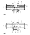
- Fig. 3
- eine Draufsicht auf das Kettenglied nach Fig. 1,
- Fig. 4
- eine Unteransicht des Kettengliedes nach Fig. 1,
- Fig. 5
- eine Seitenansicht einer Laufgliederkette mit mehreren Kettengliedern nach Fig. 1 mit Haft-Körpern, und
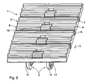
- Fig. 6
- eine perspektivische Ansicht der Laufgliederkette nach Fig. 5.
- Fig. 1
- a perspective view of a chain link of a running link chain according to the invention without adhesive body,
- Fig. 2
- a side view of the chain link according to Fig. 1,
- Fig. 3
- a plan view of the chain link according to Fig. 1,
- Fig. 4
- a bottom view of the chain link of FIG. 1,
- Fig. 5
- a side view of a track chain with multiple chain links of Figure 1 with adhesive bodies, and
- Fig. 6
- a perspective view of the Laufgliederkette of FIG. 5th
Im Folgenden wird unter Bezugnahme auf die Figuren 1 bis 6 ein Ausführungsbeispiel einer Laufgliederkette beschrieben. Eine als Ganzes mit 1 bezeichnete Laufgliederkette umfasst mehrere schwenkbar miteinander verbundene Kettenglieder 2. Jedes Kettenglied 2 weist einen Befestigungs-Grundkörper 3 sowie einen Lauf-Körper 4 auf, wobei der Befestigungs-Grundkörper 3 mittig am Lauf-Körper 4 angeordnet ist. Der Lauf-Körper 4 weist eine in Spannrichtung 5 zeigende Reinigungs-Nase 6 sowie eine gegen die Spannrichtung 5 angeordnete Reinigungs-Wand 7 auf. Die Reinigungs-Nase 6 und die Reinigungs-Wand 7 des Kettengliedes 2 sind derart ausgeformt, dass sie mit der entsprechenden Reinigungs-Wand 7 und der entsprechenden Reinigungs-Nase 6 des jeweils benachbart angeordneten Kettengliedes 2 zusammenwirken. Der Lauf-Körper 4 weist an seiner dem Befestigungs-Grundkörper 3 abgewandten Außenwand drei quer zur Spannrichtung 5 angeordnete Profil-Stege 8 auf, wobei ein Profil-Steg 8 durch zwei symmetrisch zu einer in Spannrichtung 5 senkrecht zum Lauf-Körper 4 verlaufenden Mittelebene angeordnete Öffnungen 9 durchbrochen ist. In den Öffnungen 9 ist im fertig montierten Zustand der Laufgliederkette 1 ein Haft-Körper 10 formschlüssig befestigt.An exemplary embodiment of a running link chain will be described below with reference to FIGS. 1 to 6. A running link chain designated as a whole by 1 comprises a plurality of
Der Befestigungs-Grundkörper 3 weist jeweils zwei symmetrisch zu der in Spannrichtung 5 verlaufenden Mittelebene angeordnete Durchführungs-Abschnitte 11 und Zapfen-Abschnitte 12 auf, wobei jeder Zapfen-Abschnitt 12 um die Abmessung des jeweiligen Durchführungs-Abschnitts 11 quer zur Spannrichtung 5 versetzt angeordnet ist. Von jedem Zapfen-Abschnitt 12 erstreckt sich quer zur Spannrichtung 5 ein Zapfen 13 mit einem rampenförmig abgeschrägten Zapfenende 14. Zwischen den beiden Zapfen-Abschnitten 12 ist ein quer zur Spannrichtung 5 verlaufender Führungs-Steg 15 angeordnet. Jeder Durchführungs-Abschnitt 11 weist eine Durchführungs-Öffnung 16 mit vier Halte-Vorsprüngen 17 auf, welche im Wesentlichen über den halben Umfang der Durchführungs-Öffnung 16 verteilt sind. Jedes Kettenglied 2 ist einstückig aus Kunststoff gespritzt.The
Im Folgenden wird die Montage und die Funktionsweise der Laufgliederkette 1 genauer beschrieben. Zur Montage zweier benachbart angeordneter Kettenglieder 2 wird der Durchführungs-Abschnitt 11 des einen Kettengliedes 2 mit dem Zapfen-Abschnitt 12 des benachbarten Kettengliedes 2 vorzugsweise unter einem spitzen Winkel zusammengeführt. Dabei werden die beiden Kettenglieder 2 derart gegeneinander gedreht, dass zunächst ein Zapfen 13 in die entsprechende Durchführungs-Öffnung 16 eingeführt werden kann. Der zweite Durchführungs-Abschnitt 11 liegt nun auf dem abgeschrägten Zapfenende 14 des zweiten Zapfens 13 auf. Durch Druck in Richtung des abgeschrägten Zapfenendes 14 des zweiten Zapfens 13 werden die beiden Durchführungs-Abschnitte 11 elastisch aufgebogen, so dass der zweite Zapfen 13 in die zweite Durchführungs-Öffnung 16 gleitet. Die beiden Kettenglieder 2 sind nun schwenkbar miteinander verbunden. Die Montage des Halte-Körpers 10 an dem Kettenglied 2 erfolgt durch einfaches Einstecken des Haft-Körpers 10 in die Öffnungen 9. Der Haft-Körper 10 wird durch nicht näher dargestellte Rastnasen an der Unterseite des Lauf-Körpers 4 formschlüssig befestigt. Die Montage weiterer Kettenglieder 2 und Haft-Körper 10 erfolgt in entsprechender Weise.In the following, the assembly and the operation of the running
Beim Spielen mit einem Spielzeugfahrzeug, das mit der erfindungsgemäßen Laufgliederkette 1 ausgestattet ist, wird die Laufgliederkette 1 durch zwei Laufräder am Spielzeugfahrzeug, welche in die Führungs-Stege 15 der Laufgliederkette 1 eingreifen, geführt. Bei der Bewegung des Spielzeugfahrzeugs greifen die Profil-Stege 8 in den Untergrund ein und verhindern ein Gleiten der Laufgliederkette 1 über den Untergrund. Bei losem Untergrund sind die Haft-Körper 10 weitestgehend ohne Wirkung und die Haftung der Laufgliederkette 1 erfolgt fast ausschließlich über die Profil-Stege 8. Im Gegensatz dazu haben die Profil-Stege 8, welche aus Kunststoff hergestellt sind, auf glattem Untergrund wenig Haftung, so dass die Haftung der Laufgliederkette 1 fast ausschließlich über die Haft-Körper 10, welche aus einem thermoplastischen Elastomer bestehen, erzeugt wird. Bei der Bewegung der Laufgliederkette 1 auf losem Untergrund sammelt sich zwischen den einzelnen Kettengliedern Schmutz an, beispielsweise in Form von Sand. Durch den Schwenkvorgang zweier benachbart angeordneter Kettenglieder 2 bei einem Bewegungsrichtungswechsel der Kettenglieder 2 wirkt die Reinigungs-Nase 6 des einen Kettengliedes 2 mit der Reinigungs-Wand 7 des benachbarten Kettengliedes zusammen, so dass der zwischen den beiden Kettengliedern 2 angesammelte Schmutz entfernt wird. Die Laufgliederkette reinigt die Zwischenräume zwischen den Kettengliedern 2 während der Fahrt somit selbsttätig. Eine weitere selbstreinigende Wirkung wird durch die Halte-Vorsprünge 17 in den Durchführungs-Öffnungen 16 erzielt. Bei dem Schwenkvorgang zweier benachbarter Kettenglieder 2 werden die beiden Zapfen 13 des einen Kettengliedes 2 in den Durchführungs-Öffnungen 16 des benachbart angeordneten Kettengliedes 2 gedreht. Die beiden Zapfen 13 sind dabei mit einem gewissen Spiel in den jeweiligen Durchführungs-Öffnungen 16 gelagert. Sammelt sich während der Fahrt zwischen den Zapfen 13 und den jeweiligen Durchführungs-Öffnungen 16 Schmutz an, so wird dieser Schmutz bei dem Schwenkvorgang zweier benachbarter Kettenglieder 2 durch die Halte-Vorsprünge 17 von den Zapfen 13 entfernt und kann auf Grund des Spiels anschließend von den Halte-Vorsprüngen 17 leicht abfallen.When playing with a toy vehicle, which is equipped with the running
Claims (9)
- Running link chain (1) for a toy vehicle of the shovel excavator type, wherein the running link chain (1) comprises a plurality of chain links (2) with at least one securing base (3) and at least one running body (4) respectively, and two adjacently arranged chain links (2) can be connected to each other so as to be able to pivot, wherein the at least one running body (4) has at least one cleaning lug (6) pointing in the clamping direction (5) for cleaning the adjacently arranged chain link (2), characterised in that the at least one running body (4) has at least one opening (9) for the securing of an adhesive body (10), and in the at least one opening (9) an adhesive body (10) can be fixed by interference fit for improving the adhesion of the running link chain (1) on a smooth base.
- Running link chain according to claim 1, characterised in that the at least one running body (4) has at least one cleaning wall (7) arranged counter to the clamping direction (5), which is formed in such a way that it can be cleaned by the cleaning lug (6) of the adjacently arranged chain link (2).
- Running link chain according to claim 1 or 2, characterised in that the at least one running body (4) has least one profiled web (8) arranged transversely to the clamping direction (5) on its outer wall remote from the securing base (3).
- Running link chain according to any one of claims 1 to 3, characterised in that the at least one securing base (3) has at least one guiding web (15), extending transversely to the clamping direction (5), for guiding the running link chain (1) on the toy vehicle.
- Running link chain according to any one of claims 1 to 4, characterised in that the at least one securing base (3) comprises at least one feedthrough portion (11) and at least one journal portion (12) arranged offset transversely to the clamping direction (5) by the dimensions of the feedthrough portion (11).
- Running link chain according to claim 5, characterised in that the at least one journal portion (12) has a journal (13) extending transversely to the clamping direction (5) with a ramp-shaped bevelled journal end (14).
- Running link chain according to claim 6, characterised in that a feedthrough opening (16) is provided with at least one holding projection (17) for receiving and fixing the journal (13) in the feedthrough portion (11).
- Running link chain according to any one of the preceding claims, characterised in that each chain link (2) is injected in one piece from plastics material.
- Running link chain according to any one of claims 1 to 8, characterised in that the running link chain (1) comprises a plurality of chain links (2) with at least one securing base (3) and at least one running body (4) respectively, and two adjacently arranged chain links (2) can be connected to each other so as to be able to pivot, wherein the at least one running body (4) has at least one cleaning lug (6) pointing in the clamping direction (5) for cleaning the adjacently arranged chain link (2), wherein each chain link (2) has at least one feedthrough opening (16) with at least one holding projection (17) for removing dirt on at least one journal (13) of the adjacent chain link (2) by a pivoting action.
Applications Claiming Priority (2)
| Application Number | Priority Date | Filing Date | Title |
|---|---|---|---|
| DE202004005861U | 2004-04-14 | ||
| DE202004005861U DE202004005861U1 (en) | 2004-04-14 | 2004-04-14 | Running link chain for toy vehicles in the manner of a shovel excavator |
Publications (2)
| Publication Number | Publication Date |
|---|---|
| EP1586359A1 EP1586359A1 (en) | 2005-10-19 |
| EP1586359B1 true EP1586359B1 (en) | 2007-05-02 |
Family
ID=32520736
Family Applications (1)
| Application Number | Title | Priority Date | Filing Date |
|---|---|---|---|
| EP05004095A Expired - Lifetime EP1586359B1 (en) | 2004-04-14 | 2005-02-25 | Endless track for a toy vehicle in form of a shovel excavator |
Country Status (4)
| Country | Link |
|---|---|
| EP (1) | EP1586359B1 (en) |
| AT (1) | ATE361135T1 (en) |
| DE (2) | DE202004005861U1 (en) |
| ES (1) | ES2286726T3 (en) |
Family Cites Families (3)
| Publication number | Priority date | Publication date | Assignee | Title |
|---|---|---|---|---|
| US4128277A (en) * | 1977-06-02 | 1978-12-05 | Caterpillar Tractor Co. | Lateral stiffener for track shoes |
| WO1996000676A1 (en) * | 1994-06-30 | 1996-01-11 | Fukuyama Gomu Kogyo Kabushiki Gaisha | Rubber pad |
| US20030104756A1 (en) * | 2001-12-04 | 2003-06-05 | Gordon Andrew W. | Remote-controlled, work-capable miniature vehicle |
-
2004
- 2004-04-14 DE DE202004005861U patent/DE202004005861U1/en not_active Expired - Lifetime
-
2005
- 2005-02-25 ES ES05004095T patent/ES2286726T3/en not_active Expired - Lifetime
- 2005-02-25 EP EP05004095A patent/EP1586359B1/en not_active Expired - Lifetime
- 2005-02-25 DE DE502005000637T patent/DE502005000637D1/en not_active Expired - Lifetime
- 2005-02-25 AT AT05004095T patent/ATE361135T1/en not_active IP Right Cessation
Also Published As
| Publication number | Publication date |
|---|---|
| ES2286726T3 (en) | 2007-12-01 |
| DE202004005861U1 (en) | 2004-06-17 |
| DE502005000637D1 (en) | 2007-06-14 |
| EP1586359A1 (en) | 2005-10-19 |
| ATE361135T1 (en) | 2007-05-15 |
Similar Documents
| Publication | Publication Date | Title |
|---|---|---|
| DE102010021187B4 (en) | Front spoiler of a motor vehicle | |
| DE2918638A1 (en) | ARTICULATED DOORS OPEN UP TO CLOSE A VERTICAL OPENING | |
| DE19544931A1 (en) | Chain link of an energy chain with additional body | |
| EP0956988A2 (en) | Guiding rail for the sliding panel of the sliding and tilting roof assemblies in motor vehicles | |
| DE3913077A1 (en) | CHAIN LINK AND RELATED KEY | |
| DE102007058331A1 (en) | Motor vehicle seat, has bearing/connecting element formed as U-shaped molding part with U-brackets and U-bar, which form retaining chamber for retaining cross tube, and spring element loading cross tube, if element is attached on tube | |
| EP1404204B1 (en) | Vacuum cleaner with rollers | |
| EP1875107B1 (en) | Flexible drive comprising at least one guide for tensioning and/or guiding a continuous traction mechanism | |
| DE102007035145B4 (en) | Hinge arrangement for a motor vehicle door | |
| EP1462327A2 (en) | Plastic articulated arm for a windscreen wiper | |
| DE102007012931B3 (en) | Motor vehicle jack receiving device, has deep lying convex area provided at adjacent assembly fingers, where convex area includes outer diameter corresponding to another assembly finger in relaxed condition | |
| DE19820336A1 (en) | Armrest for a motor vehicle seat | |
| EP1586359A1 (en) | Endless track for a toy vehicle in form of a shovel excavator | |
| DE20302195U1 (en) | dehydrator | |
| DE102006059635A1 (en) | wiper blade | |
| EP0692218B1 (en) | Nozzle with sealing lip | |
| EP1064164B1 (en) | Sealing profile for an automobile | |
| DE2701350A1 (en) | CONNECTOR DEVICE | |
| EP1539551A1 (en) | Device for accommodating a locking element on a wiper drive | |
| EP0123260A2 (en) | Hub cap | |
| EP1493602A2 (en) | Sliding shoe for adjustable vehicle parts | |
| EP0992421B1 (en) | Flexible endless track for vehicle toy | |
| DE102010040420A1 (en) | Wiper blade with an adapter unit for attachment to a wiper arm | |
| DE2501661A1 (en) | Plastic wiper arm connection - has resiliently yielding lobes with engaging stubs for wiper blade connecting joint | |
| DE202025102166U1 (en) | Connecting unit and connecting device |
Legal Events
| Date | Code | Title | Description |
|---|---|---|---|
| PUAI | Public reference made under article 153(3) epc to a published international application that has entered the european phase |
Free format text: ORIGINAL CODE: 0009012 |
|
| AK | Designated contracting states |
Kind code of ref document: A1 Designated state(s): AT BE BG CH CY CZ DE DK EE ES FI FR GB GR HU IE IS IT LI LT LU MC NL PL PT RO SE SI SK TR |
|
| AX | Request for extension of the european patent |
Extension state: AL BA HR LV MK YU |
|
| 17P | Request for examination filed |
Effective date: 20051012 |
|
| AKX | Designation fees paid |
Designated state(s): AT BE BG CH CY CZ DE DK EE ES FI FR GB GR HU IE IS IT LI LT LU MC NL PL PT RO SE SI SK TR |
|
| GRAP | Despatch of communication of intention to grant a patent |
Free format text: ORIGINAL CODE: EPIDOSNIGR1 |
|
| GRAS | Grant fee paid |
Free format text: ORIGINAL CODE: EPIDOSNIGR3 |
|
| GRAA | (expected) grant |
Free format text: ORIGINAL CODE: 0009210 |
|
| AK | Designated contracting states |
Kind code of ref document: B1 Designated state(s): AT BE BG CH CY CZ DE DK EE ES FI FR GB GR HU IE IS IT LI LT LU MC NL PL PT RO SE SI SK TR |
|
| PG25 | Lapsed in a contracting state [announced via postgrant information from national office to epo] |
Ref country code: FI Free format text: LAPSE BECAUSE OF FAILURE TO SUBMIT A TRANSLATION OF THE DESCRIPTION OR TO PAY THE FEE WITHIN THE PRESCRIBED TIME-LIMIT Effective date: 20070502 |
|
| REG | Reference to a national code |
Ref country code: GB Ref legal event code: FG4D Free format text: NOT ENGLISH |
|
| REG | Reference to a national code |
Ref country code: CH Ref legal event code: EP |
|
| GBT | Gb: translation of ep patent filed (gb section 77(6)(a)/1977) |
Effective date: 20070510 |
|
| REG | Reference to a national code |
Ref country code: IE Ref legal event code: FG4D Free format text: LANGUAGE OF EP DOCUMENT: GERMAN |
|
| REF | Corresponds to: |
Ref document number: 502005000637 Country of ref document: DE Date of ref document: 20070614 Kind code of ref document: P |
|
| PG25 | Lapsed in a contracting state [announced via postgrant information from national office to epo] |
Ref country code: SE Free format text: LAPSE BECAUSE OF FAILURE TO SUBMIT A TRANSLATION OF THE DESCRIPTION OR TO PAY THE FEE WITHIN THE PRESCRIBED TIME-LIMIT Effective date: 20070802 |
|
| ET | Fr: translation filed | ||
| PG25 | Lapsed in a contracting state [announced via postgrant information from national office to epo] |
Ref country code: IS Free format text: LAPSE BECAUSE OF FAILURE TO SUBMIT A TRANSLATION OF THE DESCRIPTION OR TO PAY THE FEE WITHIN THE PRESCRIBED TIME-LIMIT Effective date: 20070902 |
|
| PG25 | Lapsed in a contracting state [announced via postgrant information from national office to epo] |
Ref country code: PL Free format text: LAPSE BECAUSE OF FAILURE TO SUBMIT A TRANSLATION OF THE DESCRIPTION OR TO PAY THE FEE WITHIN THE PRESCRIBED TIME-LIMIT Effective date: 20070502 |
|
| REG | Reference to a national code |
Ref country code: ES Ref legal event code: FG2A Ref document number: 2286726 Country of ref document: ES Kind code of ref document: T3 |
|
| REG | Reference to a national code |
Ref country code: IE Ref legal event code: FD4D |
|
| PG25 | Lapsed in a contracting state [announced via postgrant information from national office to epo] |
Ref country code: SI Free format text: LAPSE BECAUSE OF FAILURE TO SUBMIT A TRANSLATION OF THE DESCRIPTION OR TO PAY THE FEE WITHIN THE PRESCRIBED TIME-LIMIT Effective date: 20070502 Ref country code: DK Free format text: LAPSE BECAUSE OF FAILURE TO SUBMIT A TRANSLATION OF THE DESCRIPTION OR TO PAY THE FEE WITHIN THE PRESCRIBED TIME-LIMIT Effective date: 20070502 Ref country code: BG Free format text: LAPSE BECAUSE OF FAILURE TO SUBMIT A TRANSLATION OF THE DESCRIPTION OR TO PAY THE FEE WITHIN THE PRESCRIBED TIME-LIMIT Effective date: 20070802 Ref country code: IE Free format text: LAPSE BECAUSE OF FAILURE TO SUBMIT A TRANSLATION OF THE DESCRIPTION OR TO PAY THE FEE WITHIN THE PRESCRIBED TIME-LIMIT Effective date: 20070502 Ref country code: PT Free format text: LAPSE BECAUSE OF FAILURE TO SUBMIT A TRANSLATION OF THE DESCRIPTION OR TO PAY THE FEE WITHIN THE PRESCRIBED TIME-LIMIT Effective date: 20071002 Ref country code: CZ Free format text: LAPSE BECAUSE OF FAILURE TO SUBMIT A TRANSLATION OF THE DESCRIPTION OR TO PAY THE FEE WITHIN THE PRESCRIBED TIME-LIMIT Effective date: 20070502 |
|
| PG25 | Lapsed in a contracting state [announced via postgrant information from national office to epo] |
Ref country code: LT Free format text: LAPSE BECAUSE OF FAILURE TO SUBMIT A TRANSLATION OF THE DESCRIPTION OR TO PAY THE FEE WITHIN THE PRESCRIBED TIME-LIMIT Effective date: 20070502 Ref country code: SK Free format text: LAPSE BECAUSE OF FAILURE TO SUBMIT A TRANSLATION OF THE DESCRIPTION OR TO PAY THE FEE WITHIN THE PRESCRIBED TIME-LIMIT Effective date: 20070502 |
|
| PLBE | No opposition filed within time limit |
Free format text: ORIGINAL CODE: 0009261 |
|
| STAA | Information on the status of an ep patent application or granted ep patent |
Free format text: STATUS: NO OPPOSITION FILED WITHIN TIME LIMIT |
|
| 26N | No opposition filed |
Effective date: 20080205 |
|
| PG25 | Lapsed in a contracting state [announced via postgrant information from national office to epo] |
Ref country code: GR Free format text: LAPSE BECAUSE OF FAILURE TO SUBMIT A TRANSLATION OF THE DESCRIPTION OR TO PAY THE FEE WITHIN THE PRESCRIBED TIME-LIMIT Effective date: 20070803 Ref country code: IT Free format text: LAPSE BECAUSE OF FAILURE TO SUBMIT A TRANSLATION OF THE DESCRIPTION OR TO PAY THE FEE WITHIN THE PRESCRIBED TIME-LIMIT Effective date: 20070502 |
|
| PG25 | Lapsed in a contracting state [announced via postgrant information from national office to epo] |
Ref country code: RO Free format text: LAPSE BECAUSE OF FAILURE TO SUBMIT A TRANSLATION OF THE DESCRIPTION OR TO PAY THE FEE WITHIN THE PRESCRIBED TIME-LIMIT Effective date: 20070502 |
|
| PG25 | Lapsed in a contracting state [announced via postgrant information from national office to epo] |
Ref country code: MC Free format text: LAPSE BECAUSE OF NON-PAYMENT OF DUE FEES Effective date: 20080228 |
|
| PG25 | Lapsed in a contracting state [announced via postgrant information from national office to epo] |
Ref country code: EE Free format text: LAPSE BECAUSE OF FAILURE TO SUBMIT A TRANSLATION OF THE DESCRIPTION OR TO PAY THE FEE WITHIN THE PRESCRIBED TIME-LIMIT Effective date: 20070502 |
|
| PGFP | Annual fee paid to national office [announced via postgrant information from national office to epo] |
Ref country code: AT Payment date: 20090121 Year of fee payment: 5 |
|
| PG25 | Lapsed in a contracting state [announced via postgrant information from national office to epo] |
Ref country code: CY Free format text: LAPSE BECAUSE OF FAILURE TO SUBMIT A TRANSLATION OF THE DESCRIPTION OR TO PAY THE FEE WITHIN THE PRESCRIBED TIME-LIMIT Effective date: 20070502 |
|
| REG | Reference to a national code |
Ref country code: CH Ref legal event code: PL |
|
| PG25 | Lapsed in a contracting state [announced via postgrant information from national office to epo] |
Ref country code: CH Free format text: LAPSE BECAUSE OF NON-PAYMENT OF DUE FEES Effective date: 20090228 Ref country code: LI Free format text: LAPSE BECAUSE OF NON-PAYMENT OF DUE FEES Effective date: 20090228 |
|
| PG25 | Lapsed in a contracting state [announced via postgrant information from national office to epo] |
Ref country code: HU Free format text: LAPSE BECAUSE OF FAILURE TO SUBMIT A TRANSLATION OF THE DESCRIPTION OR TO PAY THE FEE WITHIN THE PRESCRIBED TIME-LIMIT Effective date: 20071103 Ref country code: LU Free format text: LAPSE BECAUSE OF NON-PAYMENT OF DUE FEES Effective date: 20080225 |
|
| PG25 | Lapsed in a contracting state [announced via postgrant information from national office to epo] |
Ref country code: TR Free format text: LAPSE BECAUSE OF FAILURE TO SUBMIT A TRANSLATION OF THE DESCRIPTION OR TO PAY THE FEE WITHIN THE PRESCRIBED TIME-LIMIT Effective date: 20070502 |
|
| PG25 | Lapsed in a contracting state [announced via postgrant information from national office to epo] |
Ref country code: AT Free format text: LAPSE BECAUSE OF NON-PAYMENT OF DUE FEES Effective date: 20100225 |
|
| REG | Reference to a national code |
Ref country code: FR Ref legal event code: PLFP Year of fee payment: 12 |
|
| REG | Reference to a national code |
Ref country code: FR Ref legal event code: PLFP Year of fee payment: 13 |
|
| REG | Reference to a national code |
Ref country code: FR Ref legal event code: PLFP Year of fee payment: 14 |
|
| P01 | Opt-out of the competence of the unified patent court (upc) registered |
Effective date: 20230519 |
|
| PGFP | Annual fee paid to national office [announced via postgrant information from national office to epo] |
Ref country code: ES Payment date: 20240319 Year of fee payment: 20 Ref country code: NL Payment date: 20240220 Year of fee payment: 20 |
|
| PGFP | Annual fee paid to national office [announced via postgrant information from national office to epo] |
Ref country code: GB Payment date: 20240222 Year of fee payment: 20 |
|
| PGFP | Annual fee paid to national office [announced via postgrant information from national office to epo] |
Ref country code: FR Payment date: 20240222 Year of fee payment: 20 Ref country code: BE Payment date: 20240219 Year of fee payment: 20 |
|
| PGFP | Annual fee paid to national office [announced via postgrant information from national office to epo] |
Ref country code: DE Payment date: 20240426 Year of fee payment: 20 |
|
| REG | Reference to a national code |
Ref country code: DE Ref legal event code: R071 Ref document number: 502005000637 Country of ref document: DE |
|
| REG | Reference to a national code |
Ref country code: NL Ref legal event code: MK Effective date: 20250224 |
|
| REG | Reference to a national code |
Ref country code: ES Ref legal event code: FD2A Effective date: 20250304 |
|
| REG | Reference to a national code |
Ref country code: GB Ref legal event code: PE20 Expiry date: 20250224 |
|
| PG25 | Lapsed in a contracting state [announced via postgrant information from national office to epo] |
Ref country code: ES Free format text: LAPSE BECAUSE OF EXPIRATION OF PROTECTION Effective date: 20250226 |
|
| PG25 | Lapsed in a contracting state [announced via postgrant information from national office to epo] |
Ref country code: GB Free format text: LAPSE BECAUSE OF EXPIRATION OF PROTECTION Effective date: 20250224 |
|
| REG | Reference to a national code |
Ref country code: BE Ref legal event code: MK Effective date: 20250225 |