EP1586335A1 - Verdunstungsvorrichtung für flüchtige Wirkstoffe - Google Patents
Verdunstungsvorrichtung für flüchtige Wirkstoffe Download PDFInfo
- Publication number
- EP1586335A1 EP1586335A1 EP04021680A EP04021680A EP1586335A1 EP 1586335 A1 EP1586335 A1 EP 1586335A1 EP 04021680 A EP04021680 A EP 04021680A EP 04021680 A EP04021680 A EP 04021680A EP 1586335 A1 EP1586335 A1 EP 1586335A1
- Authority
- EP
- European Patent Office
- Prior art keywords
- air
- refill
- fan
- diffuser device
- motor
- Prior art date
- Legal status (The legal status is an assumption and is not a legal conclusion. Google has not performed a legal analysis and makes no representation as to the accuracy of the status listed.)
- Granted
Links
Images


Classifications
-
- A—HUMAN NECESSITIES
- A61—MEDICAL OR VETERINARY SCIENCE; HYGIENE
- A61L—METHODS OR APPARATUS FOR STERILISING MATERIALS OR OBJECTS IN GENERAL; DISINFECTION, STERILISATION OR DEODORISATION OF AIR; CHEMICAL ASPECTS OF BANDAGES, DRESSINGS, ABSORBENT PADS OR SURGICAL ARTICLES; MATERIALS FOR BANDAGES, DRESSINGS, ABSORBENT PADS OR SURGICAL ARTICLES
- A61L9/00—Disinfection, sterilisation or deodorisation of air
- A61L9/015—Disinfection, sterilisation or deodorisation of air using gaseous or vaporous substances, e.g. ozone
- A61L9/04—Disinfection, sterilisation or deodorisation of air using gaseous or vaporous substances, e.g. ozone using substances evaporated in the air without heating
- A61L9/12—Apparatus, e.g. holders, therefor
- A61L9/122—Apparatus, e.g. holders, therefor comprising a fan
-
- A—HUMAN NECESSITIES
- A01—AGRICULTURE; FORESTRY; ANIMAL HUSBANDRY; HUNTING; TRAPPING; FISHING
- A01M—CATCHING, TRAPPING OR SCARING OF ANIMALS; APPARATUS FOR THE DESTRUCTION OF NOXIOUS ANIMALS OR NOXIOUS PLANTS
- A01M1/00—Stationary means for catching or killing insects
- A01M1/20—Poisoning, narcotising, or burning insects
- A01M1/2022—Poisoning or narcotising insects by vaporising an insecticide
- A01M1/2027—Poisoning or narcotising insects by vaporising an insecticide without heating
- A01M1/2033—Poisoning or narcotising insects by vaporising an insecticide without heating using a fan
-
- A—HUMAN NECESSITIES
- A01—AGRICULTURE; FORESTRY; ANIMAL HUSBANDRY; HUNTING; TRAPPING; FISHING
- A01M—CATCHING, TRAPPING OR SCARING OF ANIMALS; APPARATUS FOR THE DESTRUCTION OF NOXIOUS ANIMALS OR NOXIOUS PLANTS
- A01M1/00—Stationary means for catching or killing insects
- A01M1/20—Poisoning, narcotising, or burning insects
- A01M1/2022—Poisoning or narcotising insects by vaporising an insecticide
- A01M1/2027—Poisoning or narcotising insects by vaporising an insecticide without heating
- A01M1/2044—Holders or dispensers for liquid insecticide, e.g. using wicks
-
- Y—GENERAL TAGGING OF NEW TECHNOLOGICAL DEVELOPMENTS; GENERAL TAGGING OF CROSS-SECTIONAL TECHNOLOGIES SPANNING OVER SEVERAL SECTIONS OF THE IPC; TECHNICAL SUBJECTS COVERED BY FORMER USPC CROSS-REFERENCE ART COLLECTIONS [XRACs] AND DIGESTS
- Y10—TECHNICAL SUBJECTS COVERED BY FORMER USPC
- Y10S—TECHNICAL SUBJECTS COVERED BY FORMER USPC CROSS-REFERENCE ART COLLECTIONS [XRACs] AND DIGESTS
- Y10S261/00—Gas and liquid contact apparatus
- Y10S261/88—Aroma dispensers
Definitions
- the present invention refers to a device for diffusing volatile substances with filtered and purified air into an environment.
- a motor fan sucks in the air from the environment, passing it through filters that allow the noxious particles dispersed in the air as well as the unpleasant odours to be separated and trapped.
- the air is subsequently passed though a porous material impregnated with volatile substances, and thus enriched with these aromas.
- the fan system then ensures that the treated air is expelled and diffused into the environment.
- a further drawback in both of the proposed systems is the difficulty encountered by the final user in replacing the active elements of the device, that is the filtering elements and the elements containing the volatile products, since these are integrated into the device.
- the system proposed by D. Spector has no regulation system that allows the content of volatile substances given out into the air by the device to be regulated.
- the filtering element is positioned behind the suction fan. In this manner, much of the dust contained in the air is deposited on the surface of the fan blades which, due to the continuous movement, develop a certain electrostatic charge. As the device operates, a build-up of dirt on the fan blades is therefore seen.
- evaporation of said products is favoured by the temperature.
- the heat provided by a heating element leads to an increase in the temperature of the surrounding air and thus to a heating of the surface of a material containing the specific product. This favours and accelerates the evaporation of the substance.
- European patent application EP 1 252 899 by Falchieri describes a device for diffusing volatile substances, in which the thermal gradient that is established in the device between hot parts and cold parts allows the creation of a convective movement of the air (chimney effect), which helps to disperse the evaporated substance into the environment.
- the ability to diffuse the product at a distance from the diffuser is in any case limited and proves considerably dependent upon any systems for regulation of the rate of evaporation based on direct or indirect lowering of the temperature.
- the diffuser device be provided with a blade system like that described in US Patent Application 2003/019435 by A. Pedrotti et al., which, however, has no effect on the product evaporation process.
- a considerable limitation is represented by the size of the device and by the fact that only part of the air flow generated by the blade system is exploited for diffusion of the product into the environment.
- this diffusion system requires a liquid refill, thus it must operate with a precise orientation in order to avoid leakage of the liquid from the refill.
- Object of the present invention is to eliminate the drawbacks of the prior art by providing a diffuser device for volatile substances which at the same time allows filtering of the diffused air.
- Another object of the present invention is to provide a diffuser device that is able to act on all the filtered air and at the same time it is able to carry out a fine regulation of the substances diffused.
- Yet another object of the present invention is to provide a diffuser device that is able to provide information on the state of life of the filtering means and of the diffusing means and at the same time allows an easy replacement of said filtering means and of said diffusing means.
- the diffuser device for volatile substances comprises a motor unit that can be assembled with a refill unit.
- the motor unit comprises an air suction fan comprising a body and an electric motor that drives a plurality of blades in rotation, electrical power supply means to power the fan motor electrically, and a support structure able to support the fan and the electrical power supply means.
- the refill unit comprises a refill containing volatile substances to be diffused, filtering means for air filtering and a support structure able to support the refill and the filtering means.
- the filtering means are disposed upstream of the fan to filter all the air sucked in by the fan.
- the fan body has an air inlet aperture that allows an incoming flow of air along the axis of rotation of the fan blades and an outlet aperture disposed so as to allow a laminar outgoing air flow, substantially at right angles to the incoming air flow.
- the laminar outgoing air flow strikes the refill to favour diffusion of the volatile substances.
- the diffuser device simultaneously allows multiple treatment of the air in a particular environment.
- the air is sucked from the environment into the device by means of said fan, passing first through a filter which, thanks to its structure with different weaves and/or because of the electrostatic characteristics of the surface of its fibres, favours trapping and elimination of polluting factors such as dust, unpleasant odours, smoke, etc.
- the air thus filtered is subsequently forced along a particular channel where, sweeping the surface of the refill containing a specific product to be evaporated, it favours evaporation of said product.
- the surface of the refill struck by the flow of air can be formed by a membrane permeable to the vapours of the product or by a porous element that is in contact with and is soaked with the liquid of the refill.
- the filtered air is enriched with specific products such as medicaments, decongestants, repellents, insecticides, bactericides, deodorants and the like and is released into the environment again through an outlet hole.
- the flow of air generated by the blade device ensures an adequate diffusion into the environment of the treated air enriched with specific substances.
- Operation of the diffuser device is conditioned by the presence of the refill body which also acts as the activator of the entire system.
- the diffuser device is further provided with an operating light which allows the device to be used also as a night light.
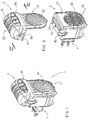
- Figure 1 shows the diffuser device according to the invention in its entirety, denoted by reference numeral 1.
- the diffuser device 1 comprises two main assemblies: a motor assembly 2 and a refill assembly 3.
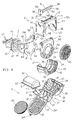
- the motor assembly 2 comprises a fan 6 driven by a motor M1 of the brushless type.
- the motor M1 has a rotor which drives in rotation a plurality of blades 61.
- the rotor of the motor M1 is mounted rotatably in a fan body 60 shaped like a substantially flattened box with the bottom peripheral edge substantially curved.
- a circular front aperture 62 having a large enough diameter to leave the blades 61 uncovered is provided in the front wall of the fan body 60.
- a rectangular top aperture 63 is provided in the top wall of the fan body 60. In this manner, when the blades 61 turn, driven by the motor M1, the air is sucked in by the front inlet aperture 62 and exits from the top outlet aperture 63.
- the motor assembly 2 comprises an electric plug 4 which allows the diffuser device 1 to be connected to the electrical main.
- the electrical plug 4 comprises a plug body 40 wherefrom the male pins 41 protrude for insertion in an electrical socket of the electrical main.
- a circular flange 42 At the front of the plug body 40 there is provided a circular flange 42 which defines a peripheral annular seat 43.
- the pins 41 of the plug are connected electrically, by means of electrical cables 44, to a printed circuit board 5 wherein the operating circuitry for the diffuser device 1 is integrated.
- the bottom edge of the board 5 is substantially curved.
- the board 5 comprises:
- a resistor bridge consisting of four resistors R1, R2, R3 and R4 is connected to the supply pad J2.
- the resistor bridge is able to create a reduction in the alternating voltage coming from the electric main and to prepare a suitable current to supply to the motor M1.
- the resistor bridge comprises a first resistive branch (R1 in parallel with R2) and a second resistive branch (R3 in parallel with R4) connected to a LED D3 able to give out a light signal indicating operation of the diffuser device 1.
- a normally open switch SW1 is connected to the outlet of the resistor bridge and of the LED D3.
- the resistors R1, R2, R3 and R4 are disposed in the front surface of the circuit board 5.
- the LED D3 and the switch SW1 are disposed on the top edge of the circuit board 5.
- the switch SW1 is controlled mechanically and is closed by pressing a lever 50 disposed in its top surface.
- the windings of the motor M1 are connected to electrical cables 55 and 56, which are connected to the output pads J3 and J4 for the power supply to the electric motor M1.
- each slot 64 able to accommodate the resistors R1, R2, R3 and R4 of the circuit board 5 are provided in the rear wall of the fan body.
- the resistors R1, R2, R3 and R4 are partially inserted in the body 60 of the fan 6. This arrangement allows the air sucked in by the fan blades 62 to be exploited for cooling the surface of said resistors, thus improving the thermal dissipation thereof and reducing damage thereto with operation.
- structures or spacers are provided to keep the circuit board 5 at a distance from the fan body 60.
- the motor assembly 2 further comprises a supporting and containing structure consisting of a bottom half-shell 20 and a top half-shell 21.
- the bottom half-shell 20 is substantially semi-cylindrical in shape and comprises, starting from its front part:
- Two slots 27 are provided in the top side edges of the bottom half-shell 20.
- the top half-shell 21 is shaped as a small parallelepiped block in the form of a bridge.
- the side walls of the top half-shell 21 have two flexible tongues 28 able to engage in a snap-in coupling relationship in the slots 27 of the bottom half-shell 20.
- Two seats 125 to receive the peripheral side edges 134 of the bottom structure 31 of the refill body are provided in the front part of the top half-shell 21.
- a knob 83 which has an indicator 84 which points to a graduated scale 74 realised on a side wall of the top half-shell 21 is integral with one end of the shaft 80.
- the graduated scale 74 indicates the amount of volatile substances diffused by the diffuser device 1, according to the regulation performed.
- the refill unit 3 comprises:
- the support structure 30 comprises a bottom portion 31 hinged to a top portion 32 along a hinging line 33 so that it can be shut like a book.
- the top portion 32 has a concave housing 39 designed to accommodate the refill 9.
- the bottom part 31 has a chamber 36 comprising a slot 92 to allow the air to exit to the outside. Furthermore, in the bottom portion 31 there are two retaining tongues 37 able to engage in a snap coupling relationship inside respective seats 38 formed in the housing 39 of the top portion 32.
- an abutment surface 97 is provided from which protrudes a pin 91 able to engage in the hole 70 of the top half shell 21 so as to operate the lever 50 which closes the switch SW1 of the circuit board 5.
- the refill 9 has a curved top wall 94 and a flat bottom wall 95 provided with an inclined flap 96.
- the refill 9 is inserted in the top housing 39 ( Figure 3) so that the flap 96 abuts against the abutment surface 97 of the top housing 39 and the top wall 94 of the refill abuts on the inside surface of the housing 39 of the top portion 32.
- the flat bottom wall 95 of the refill 9, on the other hand, faces towards the grille 92 of the chamber 36 of the bottom portion 31.
- the bottom surface 95 of the refill 9 is positioned with an inclination of about 45° with respect to the plane of the aperture 98 for entry of the air sucked in by the fan 6. In this manner, the vertical air flow which enters the aperture 98 strikes the bottom surface 95 of the refill with an optimal angle of incidence to generate a laminar effect and to increase the efficiency of evaporation of the product.
- the inclination of the deflector device 8 By changing the inclination of the deflector device 8, the direction of flow of the incoming air is changed and thus the conditions of evaporation of the system are changed.
- the refill 9 is made of impermeable material and is closed by its bottom surface 95 which represents the evaporation surface for the product contained in the reservoir.
- the bottom surface 95 of the refill can be formed by a membrane permeable to the vapours of the product or by a porous element that remains impregnated with the product. Before use, said bottom surface 95 is protected with a peelable impermeable film. Said film is removed when the refill 9 is positioned inside its housing 39.
- the material used for the refill 9 is transparent. In this manner the user can see how much liquid is still present in the refill 9 or if said liquid is finished, indicating the end of the product's life.
- the bottom portion 31 comprises:
- a circular seat 35 able to receive the filtering means 90 which are disc-shaped is formed in the inner surface of the grille part 34.
- the grille part 34 is disposed in front of the grille 23 of the motor body 2.
- the filtering element 90 has a fibrous "woven" structure able to obtain a mechanical action of retaining the dust particles contaminating the air. Furthermore, because of the mechanical rubbing action related to the continuous passage of air sucked in by the movement of the fan blades 62, an electrostatic charge able to attract and to retain the particles that pass through the filter develops on the surface of the fibres of the filter 90.
- the filter 90 preferably comprises a sequence of filtering elements with a different "mesh" to block dust particles of very small size.
- the filtering and purifying function of the filter 90 can be enriched by choosing filtering elements made up of specific materials, such as polyester-based reticulated polyurethane foams, with a complementary open cell structure.
- the calibrated, complementary open cell structure ensures a reproducible filtering efficiency, whilst the three-dimensional structure allows high dust retention without significantly affecting the pressure drop through the filtering element 90.
- a further factor to increase the functionality of the filtering element could be to treat the surface of the fibres making up the filter with specific products, so as to exert a chemical action that facilitates the trapping of unpleasant odours and of smoke present in the air sucked in.
- the filter 90 is made with materials in light colours which, due to the filtering action, change colour as they become "dirty" and provide an easy, simple indication that the filter is exhausted.
- the pin 91 of the refill body 3 operates the lever 50 of the switch SW1 and both the fan 6 and the signal light D3 are powered.
- the air is sucked in by the fan 6 along the horizontal axis of rotation of the blades 62.
- the horizontal air flow is transformed into a vertical air flow which passes though the top opening 63 of the fan body.
- the vertical air flow exiting through the top aperture of the fan body passes through the array of slots 71 of the regulation device 8 and the bottom aperture 98 of the bottom part 31 of the refill body.
- the vertical air flow strikes the bottom wall 95 of the refill, which is disposed inclined, and is transformed into a laminar flow which is expelled to the outside through the apertures of the grille 92 of the refill body.
- Another important aspect to be underlined is the fact that by moving the air with the fan 6, diffusion into the outside environment of the volatile product contained in the refill 9 is favoured, preventing the volatile product from remaining localised only near the diffuser device 1.
- the diffuser device 1 can have an ioniser (per se known and therefore not shown) disposed downstream of the fan 6. In this manner the air, before being enriched with particular substances and introduced into the environment, could also be ionised, favouring the creation of negative ions which are particularly important in order to have a healthier environment.
- an ioniser per se known and therefore not shown
- the diffuser device 1 is designed to ensure a regulation of the amount of volatile product to be introduced into the environment. Said regulation can be achieved by means of a shutter regulation device 8, changing the direction of flow of the air and thus reducing/increasing the amount of air forced into the air passage channel toward the outside.
- a second regulation device (not illustrated), able to change the exposed surface of the permeable wall 95 of the refill 9 in contact with the air flow drawn by the fan 6, can be provided.
- a screen can be provided in front of the permeable wall 95 of the refill that is operated manually by the user to vary the exposed surface of the permeable wall 95 of the refill 9.
- the light signal D3 also acts as a night light or as a position light.
- the top part 32 of the refill body 3 must be transparent to the light coming from the signal light D3 or alternatively the signal light D3 must not be covered by the refill body 3.
- the evaporation system according to the invention has the following advantages.
- the particular support structure 30 of the refill unit 3 containing the various functional elements (the filters 90 and the refill 9) disposed so as to be easily replaceable makes it possible to obtain an extremely versatile device with small dimensions, operating in any position and orientation and aesthetically pleasing.
- the system of filters 90 disposed in front of the fan allows all the air sucked in by the fan to be purified, capturing the particles present in the air mechanically, chemically or by means of an electrostatic charge. Said filters 90 also allow unpleasant odours present in the air to be reduced and removed.
- the colour of the new filters is advantageously white. As they are exhausted, becoming “dirty” with the captured particles, they change colour, thus providing a simple indicator of the end of the filtering system's life.
- the refill 9 enriches the filtered air with specific products such as medicaments, decongestants, repellents, insecticides, bactericides, deodorants and the like. It serves as a reservoir where the product to be evaporated is stored and thus allows prolonged action over time.
- the refill is advantageously made of transparent material so as to easily verify when the product to be evaporated has been used up, thus providing a simple indication of the end of the life of the product.
- the deflector regulation system 8 ensures a regulation of the amount of substances evaporated in the unit of time and thus of the content of volatile elements diffused by the device. Said deflector 8 changes the direction of the flow of the air generated by the fan 6, thus the amount of air that sweeps the permeable surface 95 of the refill increases and/or decreases, regulating the amount of product evaporated.
- the thrust action of the fan 6 ensures that the air - purified, filtered and subsequently enriched with specific volatile substances - is re-introduced into the environment through the outlet aperture grille 92 and is diffused evenly and well away from the diffuser device 1.
- the diffuser device 1 works only when assembled, that is when the structure 30 containing the filter and the refill is inserted and coupled to the structure (20, 21) of the motor unit 3. In fact the pin 91 of the support structure 30 activates the switch SW1 for operation of the fan motor M1.
- a signal light D3 which, during possible night-time operation, also acts as a night light or signal light signals.
Landscapes
- Life Sciences & Earth Sciences (AREA)
- Pest Control & Pesticides (AREA)
- Health & Medical Sciences (AREA)
- General Health & Medical Sciences (AREA)
- Insects & Arthropods (AREA)
- Environmental Sciences (AREA)
- Zoology (AREA)
- Wood Science & Technology (AREA)
- Toxicology (AREA)
- Engineering & Computer Science (AREA)
- Public Health (AREA)
- Veterinary Medicine (AREA)
- Animal Behavior & Ethology (AREA)
- Epidemiology (AREA)
- Disinfection, Sterilisation Or Deodorisation Of Air (AREA)
- Seasonings (AREA)
- Signal Processing For Digital Recording And Reproducing (AREA)
- Mechanical Treatment Of Semiconductor (AREA)
- Vaporization, Distillation, Condensation, Sublimation, And Cold Traps (AREA)
- Filtering Of Dispersed Particles In Gases (AREA)
Applications Claiming Priority (2)
| Application Number | Priority Date | Filing Date | Title |
|---|---|---|---|
| IT000681A ITMI20040681A1 (it) | 2004-04-06 | 2004-04-06 | Dispositivo emanatore per sostanze volatili |
| ITMI20040681 | 2004-04-06 |
Publications (2)
| Publication Number | Publication Date |
|---|---|
| EP1586335A1 true EP1586335A1 (de) | 2005-10-19 |
| EP1586335B1 EP1586335B1 (de) | 2007-05-30 |
Family
ID=34926512
Family Applications (1)
| Application Number | Title | Priority Date | Filing Date |
|---|---|---|---|
| EP04021680A Expired - Lifetime EP1586335B1 (de) | 2004-04-06 | 2004-09-13 | Verdunstungsvorrichtung für flüchtige Wirkstoffe |
Country Status (6)
| Country | Link |
|---|---|
| US (1) | US7204870B2 (de) |
| EP (1) | EP1586335B1 (de) |
| AT (1) | ATE363296T1 (de) |
| DE (1) | DE602004006717T2 (de) |
| ES (1) | ES2287616T3 (de) |
| IT (1) | ITMI20040681A1 (de) |
Cited By (10)
| Publication number | Priority date | Publication date | Assignee | Title |
|---|---|---|---|---|
| WO2008034053A1 (en) * | 2006-09-15 | 2008-03-20 | The Dial Corporation | Rotatable compact air purifier |
| FR2946256A1 (fr) * | 2009-06-05 | 2010-12-10 | Valeo Systemes Thermiques | Cartouche pour le traitement de l'air d'un habitacle de vehicule muni d'un filtre, et dispositif de diffusion d'un agent volatil comprenant une telle cartouche |
| USD634417S1 (en) | 2010-04-23 | 2011-03-15 | S.C. Johnson & Son, Inc. | Dispenser housing |
| USD634415S1 (en) | 2010-04-15 | 2011-03-15 | S.C. Johnson & Son, Inc. | Dispenser housing |
| USD634416S1 (en) | 2010-04-23 | 2011-03-15 | S.C. Johnson & Son, Inc. | Dispenser housing |
| USD634832S1 (en) | 2010-04-23 | 2011-03-22 | S.C. Johnson & Son, Inc. | Dispenser housing |
| USD636476S1 (en) | 2010-04-19 | 2011-04-19 | S.C. Johnson & Son, Inc. | Dispenser housing |
| USD636860S1 (en) | 2010-04-22 | 2011-04-26 | S.C. Johnson & Son, Inc. | Dispenser housing |
| USD652500S1 (en) | 2010-04-15 | 2012-01-17 | S.C. Johnson & Son, Inc. | Dispenser housing |
| WO2015092103A1 (es) * | 2013-12-19 | 2015-06-25 | Zobele España, S.A. | Sistema de liberación de sustancias volátiles |
Families Citing this family (32)
| Publication number | Priority date | Publication date | Assignee | Title |
|---|---|---|---|---|
| CA2483684C (en) | 2002-05-13 | 2010-07-06 | S. C. Johnson & Son, Inc. | Coordinated emission of fragrance, light, and sound |
| ES2403514T3 (es) | 2003-02-07 | 2013-05-20 | S.C. Johnson & Son, Inc. | Difusor con iluminación nocturna de LED (diodo emisor de luz) |
| US7163320B2 (en) * | 2004-11-29 | 2007-01-16 | Yao-Huang Liu | Grille having light emitting effect |
| US7589340B2 (en) | 2005-03-31 | 2009-09-15 | S.C. Johnson & Son, Inc. | System for detecting a container or contents of the container |
| USD541922S1 (en) | 2005-03-31 | 2007-05-01 | S.C. Johnson & Son, Inc. | Diffuser |
| US7281811B2 (en) | 2005-03-31 | 2007-10-16 | S. C. Johnson & Son, Inc. | Multi-clarity lenses |
| USD542400S1 (en) | 2005-03-31 | 2007-05-08 | S.C. Johnson & Son, Inc. | Diffuser |
| US7643734B2 (en) | 2005-03-31 | 2010-01-05 | S.C. Johnson & Son, Inc. | Bottle eject mechanism |
| US20070021783A1 (en) * | 2005-07-20 | 2007-01-25 | Aida Viana | Vaporizer pacifier |
| US7840123B2 (en) | 2007-06-21 | 2010-11-23 | S.C. Johnson & Son, Inc. | Diffusion device |
| US7938338B2 (en) * | 2007-11-01 | 2011-05-10 | Omar Janakat | Air freshener apparatus |
| US20100044468A1 (en) * | 2008-06-26 | 2010-02-25 | Momentum Industries, Llc | Device for distributing volatile fluids in air |
| US20100000413A1 (en) * | 2008-07-01 | 2010-01-07 | Hamilton Beach Brands, Inc. | Air filtration device |
| CN101363612B (zh) * | 2008-09-02 | 2011-01-12 | 宁波天瑞电器有限公司 | 驱蚊照明灯 |
| US20100326280A1 (en) * | 2009-06-30 | 2010-12-30 | Sharon Hicks | Car plug-in scented air freshener |
| US8371740B2 (en) * | 2009-12-06 | 2013-02-12 | Marcus Pestl | Continuous fragrance and illumination device with replaceable fragrance refills |
| US8783888B2 (en) | 2010-07-20 | 2014-07-22 | Winvic Sales Inc. | Flameless candle with fragrance diffusion |
| WO2012118927A1 (en) | 2011-03-01 | 2012-09-07 | S. C. Johnson & Son, Inc. | Drive module assembly and method of assembling same |
| US8821171B2 (en) * | 2011-09-22 | 2014-09-02 | S.C. Johnson & Son, Inc. | Rotatable plug assembly and housing for a volatile material dispenser |
| US9149031B2 (en) | 2013-09-13 | 2015-10-06 | S.C. Johnson & Son, Inc. | Portable area repellent device |
| US9352062B2 (en) | 2013-10-30 | 2016-05-31 | S.C. Johnson & Son, Inc. | Wearable chemical dispenser |
| US9352064B2 (en) | 2014-06-05 | 2016-05-31 | S. C. Johnson & Son, Inc. | Wearable chemical dispenser |
| US9717815B2 (en) | 2014-07-30 | 2017-08-01 | Georgia-Pacific Consumer Products Lp | Air freshener dispensers, cartridges therefor, systems, and methods |
| US10265431B2 (en) | 2017-06-08 | 2019-04-23 | Henkel IP & Holding GmbH | Volatile diffuser pods and related systems |
| USD868202S1 (en) * | 2017-10-17 | 2019-11-26 | Zobele Holding S.P.A. | Diffusing evaporator for active substances for insects |
| EP3713611B1 (de) * | 2017-11-24 | 2024-04-03 | Tiberi, Stefano | Freistehende ökologische mehrzweckvorrichtung aus einem pflanzenpolymer, vorzugsweise aus karton, zur progressiven freisetzung von aroma- und duftstoffen in die umgebung |
| USD890291S1 (en) * | 2019-02-06 | 2020-07-14 | Dynamic Solutions Worldwide, LLC | Plug in insect trap with adhesive fan |
| US11484022B2 (en) | 2019-10-15 | 2022-11-01 | S. C. Johnson & Son, Inc. | Insect trap device |
| US12290060B2 (en) | 2019-10-15 | 2025-05-06 | S. C. Johnson & Son, Inc. | Insect trap device |
| US11464882B2 (en) * | 2020-01-10 | 2022-10-11 | 1St Sense Technologies Llc | Dry diffuser apparatus and method |
| CN111184955A (zh) * | 2020-03-03 | 2020-05-22 | 河南驼人贝斯特医疗器械有限公司 | 一种新型送风装置 |
| US20240226932A9 (en) * | 2021-02-26 | 2024-07-11 | Noar Brasil Indústria E Comércio De Fragrâncias Digitais Ltda | Fragrance-release device |
Citations (9)
| Publication number | Priority date | Publication date | Assignee | Title |
|---|---|---|---|---|
| US4370300A (en) * | 1981-01-23 | 1983-01-25 | Duskin Franchise Kabushiki Kaisha | Aromatic odorant emitting device |
| US4597781A (en) | 1984-11-21 | 1986-07-01 | Donald Spector | Compact air purifier unit |
| US5735918A (en) | 1996-11-19 | 1998-04-07 | Barradas; George | Combination air freshener and air filter |
| EP0836857A1 (de) | 1996-10-15 | 1998-04-22 | Millipore S.A. | Vorrichtung zur Diffusion von flüchtigen Stoffen mit einer superhydrophoben Membran |
| US6254065B1 (en) * | 1997-07-11 | 2001-07-03 | Cws International Ag | Evaporation dispenser having a control timer for timed release of a volatile substance from an evaporation chamber |
| EP1172119A2 (de) * | 2000-07-13 | 2002-01-16 | Indest s.r.l. | Einrichtung zum Desodorieren und/oder Parfümieren von Luft |
| EP1252899A2 (de) | 2001-04-20 | 2002-10-30 | FALP S.r.l. | Spender von Luftschwebestoffen |
| US6511531B1 (en) * | 2001-01-26 | 2003-01-28 | Hmi Industries, Inc. | Room air filtering and freshening device |
| US20030019435A1 (en) | 2000-08-02 | 2003-01-30 | George Robert A. | Squirrel-proof bird feeding apparatus and method |
Family Cites Families (1)
| Publication number | Priority date | Publication date | Assignee | Title |
|---|---|---|---|---|
| KR100525070B1 (ko) * | 2003-09-29 | 2005-10-31 | 주식회사 거산 | 아로마가 발생되는 공기정화기 |
-
2004
- 2004-04-06 IT IT000681A patent/ITMI20040681A1/it unknown
- 2004-09-13 ES ES04021680T patent/ES2287616T3/es not_active Expired - Lifetime
- 2004-09-13 EP EP04021680A patent/EP1586335B1/de not_active Expired - Lifetime
- 2004-09-13 DE DE602004006717T patent/DE602004006717T2/de not_active Expired - Lifetime
- 2004-09-13 AT AT04021680T patent/ATE363296T1/de not_active IP Right Cessation
- 2004-09-15 US US10/941,683 patent/US7204870B2/en not_active Expired - Lifetime
Patent Citations (9)
| Publication number | Priority date | Publication date | Assignee | Title |
|---|---|---|---|---|
| US4370300A (en) * | 1981-01-23 | 1983-01-25 | Duskin Franchise Kabushiki Kaisha | Aromatic odorant emitting device |
| US4597781A (en) | 1984-11-21 | 1986-07-01 | Donald Spector | Compact air purifier unit |
| EP0836857A1 (de) | 1996-10-15 | 1998-04-22 | Millipore S.A. | Vorrichtung zur Diffusion von flüchtigen Stoffen mit einer superhydrophoben Membran |
| US5735918A (en) | 1996-11-19 | 1998-04-07 | Barradas; George | Combination air freshener and air filter |
| US6254065B1 (en) * | 1997-07-11 | 2001-07-03 | Cws International Ag | Evaporation dispenser having a control timer for timed release of a volatile substance from an evaporation chamber |
| EP1172119A2 (de) * | 2000-07-13 | 2002-01-16 | Indest s.r.l. | Einrichtung zum Desodorieren und/oder Parfümieren von Luft |
| US20030019435A1 (en) | 2000-08-02 | 2003-01-30 | George Robert A. | Squirrel-proof bird feeding apparatus and method |
| US6511531B1 (en) * | 2001-01-26 | 2003-01-28 | Hmi Industries, Inc. | Room air filtering and freshening device |
| EP1252899A2 (de) | 2001-04-20 | 2002-10-30 | FALP S.r.l. | Spender von Luftschwebestoffen |
Cited By (19)
| Publication number | Priority date | Publication date | Assignee | Title |
|---|---|---|---|---|
| WO2008034055A1 (en) * | 2006-09-15 | 2008-03-20 | The Dial Corporation | Fan and conforming filter for a compact air purifier |
| WO2008034049A1 (en) * | 2006-09-15 | 2008-03-20 | The Dial Corporation | Centrifugal fan for a compact air purifier |
| WO2008034053A1 (en) * | 2006-09-15 | 2008-03-20 | The Dial Corporation | Rotatable compact air purifier |
| FR2946256A1 (fr) * | 2009-06-05 | 2010-12-10 | Valeo Systemes Thermiques | Cartouche pour le traitement de l'air d'un habitacle de vehicule muni d'un filtre, et dispositif de diffusion d'un agent volatil comprenant une telle cartouche |
| USD657039S1 (en) | 2010-04-15 | 2012-04-03 | S.C. Johnson & Son, Inc. | Dispenser housing |
| USD691255S1 (en) | 2010-04-15 | 2013-10-08 | S.C. Johnson & Son, Inc. | Dispenser housing |
| USD634415S1 (en) | 2010-04-15 | 2011-03-15 | S.C. Johnson & Son, Inc. | Dispenser housing |
| USD685075S1 (en) | 2010-04-15 | 2013-06-25 | S.C. Johnson & Son, Inc. | Dispenser housing |
| USD673252S1 (en) | 2010-04-15 | 2012-12-25 | S.C. Johnson & Son, Inc. | Dispenser housing |
| USD672858S1 (en) | 2010-04-15 | 2012-12-18 | S.C. Johnson & Son, Inc. | Dispenser housing |
| USD652500S1 (en) | 2010-04-15 | 2012-01-17 | S.C. Johnson & Son, Inc. | Dispenser housing |
| USD636476S1 (en) | 2010-04-19 | 2011-04-19 | S.C. Johnson & Son, Inc. | Dispenser housing |
| USD636860S1 (en) | 2010-04-22 | 2011-04-26 | S.C. Johnson & Son, Inc. | Dispenser housing |
| USD634832S1 (en) | 2010-04-23 | 2011-03-22 | S.C. Johnson & Son, Inc. | Dispenser housing |
| USD634416S1 (en) | 2010-04-23 | 2011-03-15 | S.C. Johnson & Son, Inc. | Dispenser housing |
| USD634417S1 (en) | 2010-04-23 | 2011-03-15 | S.C. Johnson & Son, Inc. | Dispenser housing |
| WO2015092103A1 (es) * | 2013-12-19 | 2015-06-25 | Zobele España, S.A. | Sistema de liberación de sustancias volátiles |
| ES2543893A1 (es) * | 2013-12-19 | 2015-08-25 | Zobele España, S.A. | Sistema de liberación de sustancias volátiles |
| US9950090B2 (en) | 2013-12-19 | 2018-04-24 | Zobele España, S.A. | System for releasing volatile substances |
Also Published As
| Publication number | Publication date |
|---|---|
| ES2287616T3 (es) | 2007-12-16 |
| US20050218243A1 (en) | 2005-10-06 |
| EP1586335B1 (de) | 2007-05-30 |
| ATE363296T1 (de) | 2007-06-15 |
| US7204870B2 (en) | 2007-04-17 |
| DE602004006717D1 (de) | 2007-07-12 |
| ITMI20040681A1 (it) | 2004-07-06 |
| DE602004006717T2 (de) | 2008-01-24 |
Similar Documents
| Publication | Publication Date | Title |
|---|---|---|
| EP1586335B1 (de) | Verdunstungsvorrichtung für flüchtige Wirkstoffe | |
| US6413302B1 (en) | Air treatment device | |
| EP2464390B1 (de) | Tragbarer chemischer spender | |
| EP2047179B1 (de) | Luftbefeuchter mit gesteuertem wärmeduftmechanismus | |
| US7341698B2 (en) | Electrical evaporator including fan and louver structure | |
| US20080003104A1 (en) | Ceiling fan air freshener | |
| EP3061466B1 (de) | Vorrichtung und verfahren zur verbreitung einer chemischen substanz | |
| US20060288871A1 (en) | Systems for and methods of providing air purification in combination with odor elimination | |
| JP4431275B2 (ja) | 無残存式揮発性物質拡散器 | |
| US20100044468A1 (en) | Device for distributing volatile fluids in air | |
| US20090173799A1 (en) | Volatile Liquid Emitting Device | |
| EP2833988A1 (de) | Luftreinigungsvorrichtung, verfahren und system | |
| KR102882068B1 (ko) | 펫 드라이룸 | |
| US20120234175A1 (en) | Good smelling scented air filter | |
| JPH08154554A (ja) | 送風式除虫装置 | |
| JP2005076906A (ja) | 空気調節装置 | |
| WO2008034049A1 (en) | Centrifugal fan for a compact air purifier | |
| JP2004069290A (ja) | 卓上型空気清浄機 | |
| ES2386286T3 (es) | Difusor de distribución controlada para desodorantes y/o perfumes de una estancia, diseñados para montaje en pared | |
| KR20100107986A (ko) | 공기 청정기 | |
| JP2968506B2 (ja) | 芳香装置 | |
| WO2017208491A1 (ja) | 送風装置 | |
| BR8202433Y1 (pt) | Disposição introduzida em ventilador com ação odorizadora de ambientes e/ou repelente de insetos | |
| CN218511103U (zh) | 过滤组件和空调 | |
| US20220128251A1 (en) | Vent apparatuses and methods of using the same |
Legal Events
| Date | Code | Title | Description |
|---|---|---|---|
| PUAI | Public reference made under article 153(3) epc to a published international application that has entered the european phase |
Free format text: ORIGINAL CODE: 0009012 |
|
| AK | Designated contracting states |
Kind code of ref document: A1 Designated state(s): AT BE BG CH CY CZ DE DK EE ES FI FR GB GR HU IE IT LI LU MC NL PL PT RO SE SI SK TR |
|
| AX | Request for extension of the european patent |
Extension state: AL HR LT LV MK |
|
| 17P | Request for examination filed |
Effective date: 20060322 |
|
| AKX | Designation fees paid |
Designated state(s): AT BE BG CH CY CZ DE DK EE ES FI FR GB GR HU IE IT LI LU MC NL PL PT RO SE SI SK TR |
|
| GRAP | Despatch of communication of intention to grant a patent |
Free format text: ORIGINAL CODE: EPIDOSNIGR1 |
|
| GRAS | Grant fee paid |
Free format text: ORIGINAL CODE: EPIDOSNIGR3 |
|
| GRAA | (expected) grant |
Free format text: ORIGINAL CODE: 0009210 |
|
| AK | Designated contracting states |
Kind code of ref document: B1 Designated state(s): AT BE BG CH CY CZ DE DK EE ES FI FR GB GR HU IE IT LI LU MC NL PL PT RO SE SI SK TR |
|
| PG25 | Lapsed in a contracting state [announced via postgrant information from national office to epo] |
Ref country code: FI Free format text: LAPSE BECAUSE OF FAILURE TO SUBMIT A TRANSLATION OF THE DESCRIPTION OR TO PAY THE FEE WITHIN THE PRESCRIBED TIME-LIMIT Effective date: 20070530 Ref country code: LI Free format text: LAPSE BECAUSE OF FAILURE TO SUBMIT A TRANSLATION OF THE DESCRIPTION OR TO PAY THE FEE WITHIN THE PRESCRIBED TIME-LIMIT Effective date: 20070530 Ref country code: CH Free format text: LAPSE BECAUSE OF FAILURE TO SUBMIT A TRANSLATION OF THE DESCRIPTION OR TO PAY THE FEE WITHIN THE PRESCRIBED TIME-LIMIT Effective date: 20070530 |
|
| REG | Reference to a national code |
Ref country code: GB Ref legal event code: FG4D |
|
| REG | Reference to a national code |
Ref country code: CH Ref legal event code: EP |
|
| REG | Reference to a national code |
Ref country code: IE Ref legal event code: FG4D |
|
| REF | Corresponds to: |
Ref document number: 602004006717 Country of ref document: DE Date of ref document: 20070712 Kind code of ref document: P |
|
| REG | Reference to a national code |
Ref country code: DE Ref legal event code: R096 Ref document number: 602004006717 Country of ref document: DE Effective date: 20070712 |
|
| PG25 | Lapsed in a contracting state [announced via postgrant information from national office to epo] |
Ref country code: SE Free format text: LAPSE BECAUSE OF FAILURE TO SUBMIT A TRANSLATION OF THE DESCRIPTION OR TO PAY THE FEE WITHIN THE PRESCRIBED TIME-LIMIT Effective date: 20070830 |
|
| ET | Fr: translation filed | ||
| PG25 | Lapsed in a contracting state [announced via postgrant information from national office to epo] |
Ref country code: PL Free format text: LAPSE BECAUSE OF FAILURE TO SUBMIT A TRANSLATION OF THE DESCRIPTION OR TO PAY THE FEE WITHIN THE PRESCRIBED TIME-LIMIT Effective date: 20070530 Ref country code: AT Free format text: LAPSE BECAUSE OF FAILURE TO SUBMIT A TRANSLATION OF THE DESCRIPTION OR TO PAY THE FEE WITHIN THE PRESCRIBED TIME-LIMIT Effective date: 20070530 |
|
| NLV1 | Nl: lapsed or annulled due to failure to fulfill the requirements of art. 29p and 29m of the patents act | ||
| REG | Reference to a national code |
Ref country code: CH Ref legal event code: PL |
|
| REG | Reference to a national code |
Ref country code: ES Ref legal event code: FG2A Ref document number: 2287616 Country of ref document: ES Kind code of ref document: T3 |
|
| PG25 | Lapsed in a contracting state [announced via postgrant information from national office to epo] |
Ref country code: BE Free format text: LAPSE BECAUSE OF FAILURE TO SUBMIT A TRANSLATION OF THE DESCRIPTION OR TO PAY THE FEE WITHIN THE PRESCRIBED TIME-LIMIT Effective date: 20070530 |
|
| PG25 | Lapsed in a contracting state [announced via postgrant information from national office to epo] |
Ref country code: BG Free format text: LAPSE BECAUSE OF FAILURE TO SUBMIT A TRANSLATION OF THE DESCRIPTION OR TO PAY THE FEE WITHIN THE PRESCRIBED TIME-LIMIT Effective date: 20070830 Ref country code: SI Free format text: LAPSE BECAUSE OF FAILURE TO SUBMIT A TRANSLATION OF THE DESCRIPTION OR TO PAY THE FEE WITHIN THE PRESCRIBED TIME-LIMIT Effective date: 20070530 Ref country code: DK Free format text: LAPSE BECAUSE OF FAILURE TO SUBMIT A TRANSLATION OF THE DESCRIPTION OR TO PAY THE FEE WITHIN THE PRESCRIBED TIME-LIMIT Effective date: 20070530 Ref country code: CZ Free format text: LAPSE BECAUSE OF FAILURE TO SUBMIT A TRANSLATION OF THE DESCRIPTION OR TO PAY THE FEE WITHIN THE PRESCRIBED TIME-LIMIT Effective date: 20070530 Ref country code: PT Free format text: LAPSE BECAUSE OF FAILURE TO SUBMIT A TRANSLATION OF THE DESCRIPTION OR TO PAY THE FEE WITHIN THE PRESCRIBED TIME-LIMIT Effective date: 20071030 Ref country code: NL Free format text: LAPSE BECAUSE OF FAILURE TO SUBMIT A TRANSLATION OF THE DESCRIPTION OR TO PAY THE FEE WITHIN THE PRESCRIBED TIME-LIMIT Effective date: 20070530 |
|
| PG25 | Lapsed in a contracting state [announced via postgrant information from national office to epo] |
Ref country code: SK Free format text: LAPSE BECAUSE OF FAILURE TO SUBMIT A TRANSLATION OF THE DESCRIPTION OR TO PAY THE FEE WITHIN THE PRESCRIBED TIME-LIMIT Effective date: 20070530 |
|
| PLBE | No opposition filed within time limit |
Free format text: ORIGINAL CODE: 0009261 |
|
| STAA | Information on the status of an ep patent application or granted ep patent |
Free format text: STATUS: NO OPPOSITION FILED WITHIN TIME LIMIT |
|
| PG25 | Lapsed in a contracting state [announced via postgrant information from national office to epo] |
Ref country code: GR Free format text: LAPSE BECAUSE OF FAILURE TO SUBMIT A TRANSLATION OF THE DESCRIPTION OR TO PAY THE FEE WITHIN THE PRESCRIBED TIME-LIMIT Effective date: 20070831 Ref country code: MC Free format text: LAPSE BECAUSE OF NON-PAYMENT OF DUE FEES Effective date: 20070930 |
|
| 26N | No opposition filed |
Effective date: 20080303 |
|
| PG25 | Lapsed in a contracting state [announced via postgrant information from national office to epo] |
Ref country code: RO Free format text: LAPSE BECAUSE OF FAILURE TO SUBMIT A TRANSLATION OF THE DESCRIPTION OR TO PAY THE FEE WITHIN THE PRESCRIBED TIME-LIMIT Effective date: 20070530 |
|
| REG | Reference to a national code |
Ref country code: DE Ref legal event code: R097 Ref document number: 602004006717 Country of ref document: DE Effective date: 20080303 |
|
| PG25 | Lapsed in a contracting state [announced via postgrant information from national office to epo] |
Ref country code: IE Free format text: LAPSE BECAUSE OF NON-PAYMENT OF DUE FEES Effective date: 20070913 |
|
| PG25 | Lapsed in a contracting state [announced via postgrant information from national office to epo] |
Ref country code: EE Free format text: LAPSE BECAUSE OF FAILURE TO SUBMIT A TRANSLATION OF THE DESCRIPTION OR TO PAY THE FEE WITHIN THE PRESCRIBED TIME-LIMIT Effective date: 20070530 |
|
| REG | Reference to a national code |
Ref country code: DE Ref legal event code: R081 Ref document number: 602004006717 Country of ref document: DE Owner name: ZOBELE HOLDING S.P.A., IT Free format text: FORMER OWNER: ZOBELE HOLDING S.P.A., TRENTO, IT Effective date: 20081212 |
|
| PG25 | Lapsed in a contracting state [announced via postgrant information from national office to epo] |
Ref country code: CY Free format text: LAPSE BECAUSE OF FAILURE TO SUBMIT A TRANSLATION OF THE DESCRIPTION OR TO PAY THE FEE WITHIN THE PRESCRIBED TIME-LIMIT Effective date: 20070530 |
|
| REG | Reference to a national code |
Ref country code: FR Ref legal event code: TP Ref country code: FR Ref legal event code: CD |
|
| PG25 | Lapsed in a contracting state [announced via postgrant information from national office to epo] |
Ref country code: LU Free format text: LAPSE BECAUSE OF NON-PAYMENT OF DUE FEES Effective date: 20070913 |
|
| PG25 | Lapsed in a contracting state [announced via postgrant information from national office to epo] |
Ref country code: TR Free format text: LAPSE BECAUSE OF FAILURE TO SUBMIT A TRANSLATION OF THE DESCRIPTION OR TO PAY THE FEE WITHIN THE PRESCRIBED TIME-LIMIT Effective date: 20070530 Ref country code: HU Free format text: LAPSE BECAUSE OF FAILURE TO SUBMIT A TRANSLATION OF THE DESCRIPTION OR TO PAY THE FEE WITHIN THE PRESCRIBED TIME-LIMIT Effective date: 20071201 |
|
| PGFP | Annual fee paid to national office [announced via postgrant information from national office to epo] |
Ref country code: DE Payment date: 20110915 Year of fee payment: 8 |
|
| PG25 | Lapsed in a contracting state [announced via postgrant information from national office to epo] |
Ref country code: DE Free format text: LAPSE BECAUSE OF NON-PAYMENT OF DUE FEES Effective date: 20130403 |
|
| REG | Reference to a national code |
Ref country code: DE Ref legal event code: R119 Ref document number: 602004006717 Country of ref document: DE Effective date: 20130403 |
|
| REG | Reference to a national code |
Ref country code: FR Ref legal event code: PLFP Year of fee payment: 13 |
|
| REG | Reference to a national code |
Ref country code: FR Ref legal event code: PLFP Year of fee payment: 14 |
|
| REG | Reference to a national code |
Ref country code: FR Ref legal event code: PLFP Year of fee payment: 15 |
|
| PGFP | Annual fee paid to national office [announced via postgrant information from national office to epo] |
Ref country code: IT Payment date: 20220725 Year of fee payment: 19 Ref country code: GB Payment date: 20220725 Year of fee payment: 19 |
|
| PGFP | Annual fee paid to national office [announced via postgrant information from national office to epo] |
Ref country code: FR Payment date: 20220725 Year of fee payment: 19 |
|
| PGFP | Annual fee paid to national office [announced via postgrant information from national office to epo] |
Ref country code: ES Payment date: 20221004 Year of fee payment: 19 |
|
| P01 | Opt-out of the competence of the unified patent court (upc) registered |
Effective date: 20230516 |
|
| GBPC | Gb: european patent ceased through non-payment of renewal fee |
Effective date: 20230913 |
|
| PG25 | Lapsed in a contracting state [announced via postgrant information from national office to epo] |
Ref country code: GB Free format text: LAPSE BECAUSE OF NON-PAYMENT OF DUE FEES Effective date: 20230913 |
|
| PG25 | Lapsed in a contracting state [announced via postgrant information from national office to epo] |
Ref country code: GB Free format text: LAPSE BECAUSE OF NON-PAYMENT OF DUE FEES Effective date: 20230913 Ref country code: FR Free format text: LAPSE BECAUSE OF NON-PAYMENT OF DUE FEES Effective date: 20230930 |
|
| REG | Reference to a national code |
Ref country code: ES Ref legal event code: FD2A Effective date: 20241030 |
|
| PG25 | Lapsed in a contracting state [announced via postgrant information from national office to epo] |
Ref country code: IT Free format text: LAPSE BECAUSE OF NON-PAYMENT OF DUE FEES Effective date: 20230913 |
|
| PG25 | Lapsed in a contracting state [announced via postgrant information from national office to epo] |
Ref country code: IT Free format text: LAPSE BECAUSE OF NON-PAYMENT OF DUE FEES Effective date: 20230913 |
|
| PG25 | Lapsed in a contracting state [announced via postgrant information from national office to epo] |
Ref country code: ES Free format text: LAPSE BECAUSE OF NON-PAYMENT OF DUE FEES Effective date: 20230914 |
|
| PG25 | Lapsed in a contracting state [announced via postgrant information from national office to epo] |
Ref country code: ES Free format text: LAPSE BECAUSE OF NON-PAYMENT OF DUE FEES Effective date: 20230914 |