EP1586228B1 - Gewindeverbindung, insbesondere zur Befestigung eines Werkzeugs oder eines Werkzeugadapters, an einer Verlängerungseinrichtung - Google Patents
Gewindeverbindung, insbesondere zur Befestigung eines Werkzeugs oder eines Werkzeugadapters, an einer Verlängerungseinrichtung Download PDFInfo
- Publication number
- EP1586228B1 EP1586228B1 EP05000432A EP05000432A EP1586228B1 EP 1586228 B1 EP1586228 B1 EP 1586228B1 EP 05000432 A EP05000432 A EP 05000432A EP 05000432 A EP05000432 A EP 05000432A EP 1586228 B1 EP1586228 B1 EP 1586228B1
- Authority
- EP
- European Patent Office
- Prior art keywords
- connection
- thread
- recess
- tool
- cam
- Prior art date
- Legal status (The legal status is an assumption and is not a legal conclusion. Google has not performed a legal analysis and makes no representation as to the accuracy of the status listed.)
- Expired - Lifetime
Links
Images


Classifications
-
- F—MECHANICAL ENGINEERING; LIGHTING; HEATING; WEAPONS; BLASTING
- F16—ENGINEERING ELEMENTS AND UNITS; GENERAL MEASURES FOR PRODUCING AND MAINTAINING EFFECTIVE FUNCTIONING OF MACHINES OR INSTALLATIONS; THERMAL INSULATION IN GENERAL
- F16B—DEVICES FOR FASTENING OR SECURING CONSTRUCTIONAL ELEMENTS OR MACHINE PARTS TOGETHER, e.g. NAILS, BOLTS, CIRCLIPS, CLAMPS, CLIPS OR WEDGES; JOINTS OR JOINTING
- F16B7/00—Connections of rods or tubes, e.g. of non-circular section, mutually, including resilient connections
- F16B7/18—Connections of rods or tubes, e.g. of non-circular section, mutually, including resilient connections using screw-thread elements
- F16B7/182—Connections of rods or tubes, e.g. of non-circular section, mutually, including resilient connections using screw-thread elements for coaxial connections of two rods or tubes
-
- Y—GENERAL TAGGING OF NEW TECHNOLOGICAL DEVELOPMENTS; GENERAL TAGGING OF CROSS-SECTIONAL TECHNOLOGIES SPANNING OVER SEVERAL SECTIONS OF THE IPC; TECHNICAL SUBJECTS COVERED BY FORMER USPC CROSS-REFERENCE ART COLLECTIONS [XRACs] AND DIGESTS
- Y10—TECHNICAL SUBJECTS COVERED BY FORMER USPC
- Y10T—TECHNICAL SUBJECTS COVERED BY FORMER US CLASSIFICATION
- Y10T403/00—Joints and connections
- Y10T403/50—Bridged by diverse connector
-
- Y—GENERAL TAGGING OF NEW TECHNOLOGICAL DEVELOPMENTS; GENERAL TAGGING OF CROSS-SECTIONAL TECHNOLOGIES SPANNING OVER SEVERAL SECTIONS OF THE IPC; TECHNICAL SUBJECTS COVERED BY FORMER USPC CROSS-REFERENCE ART COLLECTIONS [XRACs] AND DIGESTS
- Y10—TECHNICAL SUBJECTS COVERED BY FORMER USPC
- Y10T—TECHNICAL SUBJECTS COVERED BY FORMER US CLASSIFICATION
- Y10T403/00—Joints and connections
- Y10T403/55—Member ends joined by inserted section
- Y10T403/556—Section threaded to member
Definitions
- the present invention relates to a threaded connection according to the preamble of claim 1 ( US-A-5690181 ).
- connection between the paint roller and the extension device it is known to use a threaded connection.
- the part of the threaded connection associated with the paint roller can either be arranged directly in the handle of the paint roller or on a corresponding adapter on which a paint roller or another tool can be arranged.
- At the extension device of the complementary part of the threaded connection is formed.
- the object of the invention is therefore to improve the ease of use of the threaded connection.
- the core is that the tool or the tool adapter is locked by means of a positive snap connection to the extension device.
- the locking of the threaded connection is formed in a preferred embodiment as a snap mechanism with two form-fitting interlocking elements, which can be interlocked by temporarily overcoming elastic restoring forces.
- the fixation is effected by a displacement of the corresponding locking element, so that it interacts with its counterpart.
- the snap connection can consist of a cam, a nose or the like and a recess having a corresponding counter-shape.
- the cam is arranged aligned with respect to the recess in such a way that the two snap into each other if and only when the threaded connection consisting of threaded bolts and threaded bushing comes together when screwed into its screwed position.
- an elastic abutment may be provided to form an elastic transition when setting the threaded bolt in the threaded bushing, for example in the form of a rubber which either dampens the tightening torque and / or widens the area in which the threaded bolt engages in the threaded bushing.
- This range relates to both the axial offset and the radial offset of the threaded bolt relative to the threaded bush, thereby allowing a greater tolerance in the determination of the cam in the recess can be achieved.
- this can in a next embodiment comprise a handle device, such as an actuating lever, a gripping surface or the like. By pressing the handle, the lock is released and the tool can be separated again from the extension device.
- a handle device such as an actuating lever, a gripping surface or the like.
- the handle device can be designed to spring-loaded or even form a good grip to facilitate the separation process.
- either the cam and / or the recess may be axially displaceable in order to establish or cancel the locking action of the snap connection. Preferably, this is done by means of a against the force of an elastic return means, in particular a spring, displaceable locking sleeve.
- either the cam or the recess can be formed on the locking sleeve.
- a second locking means in the form of interacting cams and recesses, e.g. for reinforcing the lock, is formed. In this case, it is advantageous if the two detents are designed so that their cams can only engage uniquely assigned in the respective associated recess.
- the cam can act on the locking sleeve when screwing the threaded bolt in the threaded sleeve axially displaceable.
- the cam can be arranged both on the locking sleeve and on the corresponding counterpart.
- an anti-twist device can be designed for it.
- a stop provides the restriction freedom of movement.
- the stopper is preferably spring-loaded in the form of a clamping pin.
- a locking means can also perform a radial offset and engage in its counterpart in its operation.
- the cam and / or the recess of the snap connection may additionally have an oblique edge or surface. This makes it possible to easily solve the locking effect of the snap connection by means of the oblique edge or surface under the action of a rotational force, but it must be ensured that the locking force is still sufficiently large, so that proper handling of the paint roller is guaranteed.
- Embodiments are possible as embodiments in which the cam snaps radially outward or radially inward into the correspondingly associated recess. Of course, a combination of such embodiments is possible.
- the recess is formed as a groove or hole.
- the groove may have the advantage over the hole that it can be designed to run all around, so that even larger manufacturing tolerances are permitted.
- the hole may have the advantage over the groove that it may possibly be made simpler.
- FIG. 1 shows a threaded connection 1 between a tool 2 and an extension device 4.
- the tool 2 is a paint roller to which a threaded bush 6 is attached to the end face of the handle opposite the bracket.
- a threaded bolt 5 of the extension device 4 are screwed in until the extension device 4 is firmly connected to the tool 2 is.
- the tool side has a cam 8 and on the side of the extension device 4 has a cam associated with the recess 9.
- FIG. 1 shows two snap connections 7 arranged radially approximately opposite one another.
- the locking sleeve 10 during the screwing together of the extension device 4 with the handle of the tool 2 according to the direction of the arrow 10a spring loaded can be moved to the right.
- the opposite to the extension device rotatable but axially displaceable locking sleeve 10 is rotated so far with respect to the tool that the cam 8 associated recess in accordance with the cam 8, it snaps back under spring force against the direction of the previously executed sliding movement and takes the Cam 8 in order to produce the locking of the threaded connection 1. Further details can be taken from FIGS. 3 and 4.
- a locking device 12 is formed on the locking sleeve 10, by means of which they in turn can be pulled back axially in a direction of the arrow 10a to the right, so that the engagement of the cam 8 is released in the recess 9, according to which the extension device 4 can again be rotated in the opposite direction relative to the tool and thus screwed on.
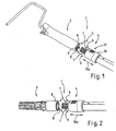
- Figure 2 shows basically the same structure of a threaded connection 1 with threaded bolt 5 and threaded bushing 6 and a lock in the form of a positive Snap connection 7.
- a tool 2 is received by the extension device 4 and in Figure 2, a tool adapter 3.
- This tool adapter 3 extends the possibility of variation of the threaded connection.
- FIG. 3 shows further details of the threaded connection.
- This anti-rotation 13 is formed between a arranged in a locking ring 15 slot 14 and engaging in this slot rib 16.
- the locking ring 15 is rotatably connected to the extension device 4.
- the locking sleeve 10 can thus be moved only in the axial direction by moving the rib 16 in the slot 14 against the spring force of the spring 11, which in turn is axially supported against the radially inserted into the extension direction 4, spring-loaded clamping pin 17.
- the locking sleeve 10 additionally has two stops 18, 19, wherein the stop 18 is formed with respect to the clamping pin 17 as arranged on the locking sleeve end side, inwardly facing flange.
- the stop 19 is in turn formed on the opposite end face of the locking sleeve 10 relative to the securing ring 15 as a radially inwardly pointing flange. The locking sleeve can thus be moved axially between these two stop positions.
- the two snap connections 7 are designed so that each cam 8, due to different radial distances to the longitudinal axis of the threaded connection, can only engage in the recess 9 assigned to it.
- FIG. 4 shows this connection in a locked state, that is, in a joined state.
- the upper snap connection 7, as described in FIG. 3, differs from the lower snap connection 7.
- FIG. 5 shows this threaded connection in a non-cut representation in an oblique plan view.
- FIGS. 6a and 6b show, as partial cut-outs, further possibilities for an elastic snap connection, in which in turn a cam 8 engages in a recess 9 associated therewith.
- the locking takes place by rotating the cam on the surface of the counterpart associated with the recess.
- the cam having locking member must be elastically deformed relative to the recess 9 having locking element until the two engage by snapping into each other.
- both the cam 8 and the recess 9 each have an inclined surface 20.
- This inclined surface 20 refers to the cross section of the illustrated embodiment. Of course, these are two opposing, diagonally arranged surfaces, which reduces the restoring force when loosening the lock so far that it is easy to solve and yet properly secures this when using the tool.
- the snap connection is formed so that the cam 8 snaps radially inward into the recess and as shown in the figure 6b, this cam engages radially outward in the recess 9 assigned to it.
- FIG. 7 shows a further embodiment in which the cam 8 snaps radially inwards into the recess assigned to it.
- a handling device 12 is arranged here, which presses from the radially opposite side from the inside out the cam, so that the lock is released.
- the edge 20 associated side of the recess 9 is rounded here, so that the release of the lock is facilitated.
- FIGS 8, 8a and 8b show a further embodiment of a lock for a threaded connection.
- the threaded bolt 6 is arranged inside the handle for the tool 2, which may optionally be surrounded by a sleeve 22 in order to form a more user-friendly grip end.
- cams 8 are arranged on elastic tongues, so that they can be bent radially inwardly.
- the cams 8 are first inserted and compressed radially inwardly.
- the cams 8 snap radially outward into the associated recess 9.
- This recess 9 can now be either a circumferential groove or holes arranged at corresponding locations. These holes can be holes, recesses or something similar.
- a handling device 12 is provided, which is formed in this case in the form of a ring having inwardly directed pins. These pins press according to the illustration in Figure 8a upon compression of the ring, the two cams 8 in the direction of the arrows 21 radially together so that they again in the direction of the threaded bushing 5 can be unscrewed axially.
- FIG. 8b is a sectional view in the plane VIII-VIII in FIG. 8.
- the sliding connection can be realized by a modified form of the snap connection 7, in which the locking sleeve 10 without the restoring spring 11 is arranged on the threaded connection 1.
- the intermeshing of the cam 8 and the recess 9, for the purpose of locking the tool 2 on the extension device 4, is then effected in this embodiment not by moving the locking sleeve by means of a spring but by manually moving.
Landscapes
- Engineering & Computer Science (AREA)
- General Engineering & Computer Science (AREA)
- Mechanical Engineering (AREA)
- Mutual Connection Of Rods And Tubes (AREA)
- Gripping On Spindles (AREA)
- Coating Apparatus (AREA)
- Details Of Spanners, Wrenches, And Screw Drivers And Accessories (AREA)
Description
- Die vorliegende Erfindung betrifft eine Gewindeverbindung nach dem Oberbegriff des Anspruchs 1 (
US-A-5690181 ). - Um Werkzeuge, insbesondere Farbroller, besser bedienen zu können, ist es bekannt, diese mit einer Verlängerungseinrichtung zu verbinden. Dadurch kann der Farbroller nicht nur an dem an ihm ausgebildeten Griff gehalten und geführt werden, sondern vorteilhafterweise über den gesamten Bereich der Verlängerungseinrichtung hinweg.
- Als Verbindung zwischen dem Farbroller und der Verlängerungseinrichtung ist es bekannt, eine Gewindeverbindung zu verwenden. Der dem Farbroller zugeordnete Teil der Gewindeverbindung kann entweder direkt im Griff des Farbrollers angeordnet sein oder an einem entsprechenden Adapter, auf dem ein Farbroller oder ein anderes Werkzeug angeordnet werden kann. An der Verlängerungseinrichtung ist der komplementäre Teil der Gewindeverbindung ausgebildet.
- Bei der Bedienung des Farbrollers kommt es jedoch immer wieder vor, dass sich die Gewindeverbindung löst, was sich nachteilig auf die Handhabung des Farbrollers auswirkt.
- Aufgabe der Erfindung ist es daher, den Bedienkomfort der Gewindeverbindung zu verbessern.
- Diese Aufgabe wird durch die Merkmale des Anspruchs 1 gelöst. In den Unteransprüchen sind vorteilhafte und zweckmäßige Verbesserungen und Weiterbildungen des Gegenstandes des Anspruchs 1 angegeben.
- Erfindungsgemäß wird deshalb eine Gewindeverbindung nach dem Oberbegriff des Anspruchs 1 vorgeschlagen, deren Kern darin liegt, dass das Werkzeug oder der Werkzeug-Adapter mittels einer formschlüssigen Schnappverbindung an der Verlängerungseinrichtung arretiert wird.
- Der Vorteil einer solchen Arretierung liegt darin, dass auf den Farbroller während seiner Verwendung, bezogen auf die Längsachse der Verlängerungseinrichtung, auch drehende Bewegungen übertragen werden können, ohne dass sich die Gewindeverbindung löst.
- Die Arretierung der Gewindeverbindung ist in einer bevorzugten Ausführungsform als Schnappmechanismus mit zwei formschlüssig ineinander eingreifenden Elementen ausgebildet, die unter vorübergehender Überwindung elastischer Rückstellkräfte ineinandergefügt werden können.
- Bei dieser rückstell-elastischen Verbindung erfolgt lediglich kurzzeitig ein Versatz oder eine Verformung wenigstens eines Arretierelementes, welches danach wieder in seine ursprüngliche Lage und/oder Form zurückkehrt.
- In einer demgegenüber abgewandelten Ausführungsform kann die arretierende, formschlüssige Verbindung aber auch als eine Schiebeverbindung, z.B. ohne elastische Rückstellkräfte, ausgebildet sein. Die Fixierung erfolgt dabei durch eine Verschiebung des entsprechenden Arretierelementes, so dass es mit seinem Gegenstück zusammenwirkt.
- In einer Weiterbildung kann die Schnappverbindung aus einem Nocken, einer Nase oder dergleichen und einer eine entsprechende Gegenform aufweisenden Aussparung bestehen. Vorteilhafterweise ist der Nocken dazu in Bezug auf die Aussparung derart ausgerichtet angeordnet, dass die beiden genau dann ineinander einschnappen, wenn die aus Gewindebolzen und Gewindebuchse bestehende Gewindeverbindung beim Zusammenschrauben in ihre festgeschraubte Position gelangt.
- Weiter vorteilhaft kann zur Ausbildung eines elastischen Übergangs beim Festsetzen des Gewindebolzens in der Gewindebuchse ein elastisches Widerlager vorgesehen sein, beispielsweise in der Form eines Gummis, der entweder das Festziehmoment dämpft und/oder den Bereich aufweitet, in welchem sich der Gewindebolzen in der Gewindebuchse festsetzt. Dieser Bereich betrifft sowohl den axialen Versatz als auch den radialen Versatz des Gewindebolzens gegenüber der Gewindebuchse, so dass dadurch eine größere Toleranz bei der Festsetzung des Nockens in der Aussparung erreicht werden kann.
- Um die Schnappverbindung wieder lösen zu können, kann diese in einer nächsten Ausführungsform eine Handhabeeinrichtung umfassen, wie beispielsweise einen Betätigungshebel, eine Greiffläche oder dergleichen. Durch Betätigen der Handhabeeinrichtung wird die Arretierung aufgehoben und das Werkzeug kann wieder von der Verlängerungseinrichtung getrennt werden.
- Die Handhabeeinrichtung kann dazu federbelastet ausgebildet sein oder selbst einen guten Halt ausbilden, um den Trennvorgang zu erleichtern.
- In einer besonders bevorzugten Ausführungsform kann entweder der Nocken und/oder die Aussparung axial verschiebbar sein, um die Arretierwirkung der Schnappverbindung herzustellen bzw. wieder aufzuheben. Vorzugsweise geschieht dies mittels einer gegen die Kraft eines elastischen Rückstellmittels, insbesondere einer Feder, verschiebbaren Arretierhülse. An der Arretierhülse kann dabei entweder der Nocken oder die Aussparung ausgebildet sein. In besonderen Ausführungsformen ist es auch möglich, dass neben einer ersten auch noch eine zweite Arretiereinrichtung in Form von ineinanderwirkenden Nocken und Aussparungen, z.B. zur Verstärkung der Arretierung, ausgebildet ist. In diesem Fall ist es vorteilhaft, wenn die beiden Arretierungen so ausgebildet sind, dass deren Nocken nur eindeutig zugeordnet in die jeweils zugeordnete Aussparung einrasten kann. Dadurch kann sichergestellt werden, dass eine ganze Gewindesteigung, also eine beinahe 360°-Verdrehung des Gewindebolzens in der Gewindebuchse, zum Vorspannen der Arretierung durch Verschieben der Arretierhülse ermöglicht werden kann, bevor die Nocken in die zugehörigen Aussparungen einrasten und die Gewindeverbindung drehfest festsetzen.
- In einer besonders bevorzugten Ausführungsform kann der Nocken auf die Arretierhülse beim Einschrauben des Gewindebolzens in die Gewindebuchse axial verschiebend wirken. Der Nocken kann dabei sowohl auf der Arretierhülse als auch am entsprechenden Gegenstück angeordnet sein.
- Um sicherzustellen, dass die Arretierhülse in ihrer Drehlage beim Zusammenschrauben der Gewindeverbindung zu dem ihr zugeordneten Element der Gewindeverbindung positionsstabil bleibt, kann für sie eine Verdrehsicherung ausgebildet sein. In Verschieberichtung sorgt ein Anschlag für die Beschränkung der Bewegungsfreiheit. Der Anschlag ist dabei vorzugsweise federbelastet in der Form eines Spannstiftes ausgebildet. Dadurch wird eine einfache Montage der Arretierhülse, beispielsweise an der Verlängerungseinrichtung, ermöglicht.
- Bei einer demgegenüber abgewandelten Ausführungsform der Arretierung kann ein Arretiermittel bei seiner Betätigung auch einen radialen Versatz ausführen und in sein Gegenstück eingreifen. Der Nocken und/oder die Aussparung der Schnappverbindung kann zusätzlich eine schräge Kante oder Fläche aufweisen. Damit ist es möglich, die Arretierwirkung der Schnappverbindung mit Hilfe der schrägen Kante oder Fläche bei Einwirkung einer Drehkraft leichter zu lösen, wobei jedoch sichergestellt sein muss, dass die Arretierkraft noch ausreichend groß ist, so dass eine einwandfreie Handhabung des Farbrollers gewährleistet ist.
- Als Ausführungsformen sind dabei Ausbildungen möglich, bei denen der Nocken radial auswärts oder radial einwärts in die entsprechend zugeordnete Aussparung einschnappt. Selbstverständlich ist auch eine Kombination solcher Ausführungsformen möglich.
- Eine weitere Ausführungsform kann beispielsweise dadurch realisiert werden, dass die Aussparung als Nut oder Loch ausgebildet ist. Die Nut kann gegenüber dem Loch den Vorteil haben, dass sie rundumlaufend ausgebildet sein kann, so dass dadurch auch größere Fertigungstoleranzen zulässig sind. Das Loch kann gegenüber der Nut den Vorteil haben, dass es gegebenenfalls einfacher ausgebildet werden kann.
- Weitere Einzelheiten und Vorteile der Erfindung werden in den Zeichnungen anhand von schematisch dargestellten Ausführungsbeispielen beschrieben.
- Im Einzelnen zeigen:
- Figur 1
- ganz allgemein eine Gewindeverbindung für die Befestigung eines Werkzeuges, welches im dargestellten Beispiel ein Farbroller ist, an einer Verlängerungseinrichtung;
- Figur 2
- eine Gewindeverbindung wie in Figur 1, jedoch anstelle des Werkzeugs einen Adapter für ein Werkzeug;
- Figur 3
- eine Schnittdarstellung der Gewindeverbindung in getrenntem Zustand der beiden Gewindeteile;
- Figuren 4, 5
- jeweils eine schräge Draufsicht auf eine Gewindeverbindung in arretiertem Zustand in geschnittener (Figur 4) und in nicht geschnittener (Figur 5) Darstellung;
- Figuren 6a, 6b, 7, 8, 8a, 8b
- zeigen verschiedene Ausführungsformen von Arretierungen und diese wieder lösende Handhabungseinrichtungen.
- Figur 1 zeigt eine Gewindeverbindung 1 zwischen einem Werkzeug 2 und einer Verlängerungseinrichtung 4. Im vorliegenden Fall ist das Werkzeug 2 ein Farbroller, an dessen dem Bügel für die Farbrolle gegenüberliegenden Stirnseite des Griffs eine Gewindebuchse 6 angebracht ist. In diese kann ein Gewindebolzen 5 der Verlängerungseinrichtung 4 so weit eingeschraubt werden, bis die Verlängerungseinrichtung 4 fest mit dem Werkzeug 2 verbunden ist.
- Als Arretierung für die Gewindeverbindung 1 ist eine formschlüssige Schnappverbindung 7 ausgebildet, die werkzeugseitig einen Nocken 8 und an der Seite der Verlängerungseinrichtung 4 eine dem Nocken zugeordnete Aussparung 9 aufweist.
- In Figur 1 sind zwei sich radial etwa gegenüberliegend angeordnete Schnappverbindungen 7 gezeigt. Um die Nocken 8 in die Aussparungen 9 einrasten zu können, kann die Arretierhülse 10 während des Zusammenschraubens der Verlängerungseinrichtung 4 mit dem Griff des Werkzeugs 2 entsprechend der Pfeilrichtung 10a federbelastet nach rechts verschoben werden. Wenn die gegenüber der Verlängerungseinrichtung drehfeste aber axial verschiebbare Arretierhülse 10 gegenüber dem Werkzeug so weit verdreht ist, dass die dem Nocken 8 zugeordnete Aussparung in Übereinstimmung mit dem Nocken 8 ist, schnappt sie unter Federkraft wieder gegen die Richtung der zuvor ausgeführten Verschiebebewegung zurück und nimmt den Nocken 8 in sich auf, um die Arretierung der Gewindeverbindung 1 herzustellen. Weitere Details sind den Figuren 3 und 4 zu entnehmen.
- Um das Lösen der Schnappverbindung 7 zu erleichtern, ist an der Arretierhülse 10 eine Handhabeeinrichtung 12 ausgebildet, mittels derer sie wiederum axial in eine Richtung des Pfeiles 10a nach rechts zurückgezogen werden kann, so dass der Eingriff des Nockens 8 in der Aussparung 9 aufgehoben wird, wonach die Verlängerungseinrichtung 4 wiederum in entgegengesetzter Richtung relativ zum Werkzeug verdreht und somit aufgeschraubt werden kann.
- Die Figur 2 zeigt grundsätzlich denselben Aufbau einer Gewindeverbindung 1 mit Gewindebolzen 5 und Gewindebuchse 6 sowie einer Arretierung in der Form einer formschlüssigen Schnappverbindung 7. Der Unterschied zwischen den Figuren 1 und 2 liegt darin, dass in Figur 1 ein Werkzeug 2 von der Verlängerungseinrichtung 4 aufgenommen ist und in der Figur 2 ein Werkzeug-Adapter 3. Dieser Werkzeug-Adapter 3 erweitert die Variationsmöglichkeit der Gewindeverbindung 1.
- Die Figur 3 zeigt weitere Details der Gewindeverbindung. Um sicherzustellen, dass sich die Arretierhülse 10 nicht gegenüber der Längsachse der Verlängerungseinrichtung 4 beim Einschrauben des Gewindebolzens 5 in die Gewindebuchse 6 verdreht, weist diese eine Verdrehsicherung 13 auf. Diese Verdrehsicherung 13 wird zwischen einem in einem Sicherungsring 15 angeordneten Schlitz 14 und einer in diesen Schlitz eingreifenden Rippe 16 ausgebildet. Der Sicherungsring 15 ist dabei drehfest mit der Verlängerungseinrichtung 4 verbunden.
- Die Arretierhülse 10 kann also lediglich in axialer Richtung durch Verschieben der Rippe 16 im Schlitz 14 gegen die Federkraft der Feder 11 verschoben werden, die sich ihrerseits gegen den radial in die Verlängerungsrichtung 4 eingesetzten, federbelasteten Spannstift 17 axial abstützt. Die Arretierhülse 10 weist zusätzlich noch zwei Anschläge 18, 19 auf, wobei der Anschlag 18 gegenüber dem Spannstift 17 als an der Arretierhülse stirnseitig angeordneter, nach innen weisender Flansch ausgebildet ist. Der Anschlag 19 ist an der dieser gegenüberliegenden Stirnseite der Arretierhülse 10 gegenüber dem Sicherungsring 15 wiederum als radial nach innen weisender Flansch ausgebildet. Die Arretierhülse kann somit zwischen diesen beiden Anschlagspositionen axial verschoben werden.
- Die beiden Schnappverbindungen 7 sind so ausgebildet, dass jeder Nocken 8, bedingt durch jeweils unterschiedliche radiale Abstände zur Längsachse der Gewindeverbindung, nur in die ihm zugeordnete Aussparung 9 einrasten kann.
- Die Figur 4 zeigt diese Verbindung nun in arretiertem, also zusammengefügtem Zustand. Auch hier ist erkennbar, dass die obere Schnappverbindung 7, wie in Figur 3 beschrieben, sich von der unteren Schnappverbindung 7 unterscheidet.
- Die Figur 5 zeigt diese Gewindeverbindung in nicht geschnittener Darstellung in schräger Draufsicht. Gut erkennbar ist wiederum die Ausbildung der Arretierung durch die formschlüssige Schnappverbindung 7 mittels des Nockens 8, welcher in die ihm zugehörige Aussparung 9 eingerastet ist.
- Die Figuren 6a und 6b zeigen als Teilausschnitte weitere Möglichkeiten einer elastischen Schnappverbindung, bei der wiederum ein Nocken 8 in eine ihm zugehörige Aussparung 9 einrastet. Gegenüber der vorigen Ausführungsform ist es hier jedoch vorgesehen, dass die Arretierung durch Verdrehen des Nockens an der der Aussparung zugeordneten Oberfläche des Gegenstücks erfolgt. Dazu muss das den Nocken aufweisende Arretierelement vorübergehend gegenüber dem die Aussparung 9 aufweisenden Arretierelement elastisch verformt werden, bis die beiden durch Einschnappen ineinander greifen. Um ein Lösen dieser Arretierung zu erleichtern, weisen in diesen beiden Ausführungsformen 6a und 6b sowohl der Nocken 8 als auch die Aussparung 9 jeweils eine schräge Fläche 20 auf. Diese schräge Fläche 20 bezieht sich auf den Querschnitt des dargestellten Ausführungsbeispiels. Selbstverständlich handelt es sich hierbei um zwei sich gegenüberliegende, schräg angeordnete Flächen, die die Rückstellkraft beim Lösen der Arretierung so weit reduziert, dass sie leicht zu lösen ist und dennoch bei der Verwendung des Werkzeugs dieses einwandfrei sichert.
- Gemäß der Darstellung der Figur 6a ist die Schnappverbindung so ausgebildet, dass der Nocken 8 radial einwärts in die Aussparung einschnappt, und gemäß der Darstellung der Figur 6b rastet dieser Nocken radial auswärts in die ihm zugeordnete Aussparung 9 ein.
- Die Figur 7 zeigt eine weitere Ausführungsform, bei der der Nocken 8 radial einwärts in die ihm zugeordnete Aussparung einschnappt. Zum Lösen ist hier eine Handhabevorrichtung 12 angeordnet, die von der radial gegenüberliegenden Seite von innen her den Nocken nach außen drückt, so dass die Arretierung gelöst ist. Zusätzlich ist auch hier die der Kante 20 zugeordneten Seite der Aussparung 9 abgerundet, so dass das Lösen der Arretierung erleichtert wird.
- Die Figuren 8, 8a und 8b zeigen eine weitere Ausführungsform einer Arretierung für eine Gewindeverbindung. Hierbei ist beispielhaft im Inneren des Griffs für das Werkzeug 2 der Gewindebolzen 6 angeordnet, welcher gegebenenfalls von einer Hülse 22 umgeben sein kann, um ein bedienfreundlicheres Griffende auszubilden. Stirnseitig sind am Gewindebolzen 6 Nocken 8 an elastischen Zungen angeordnet, so dass diese radial einwärts verbogen werden können. Beim Einschrauben des Gewindebolzens 6 in die Gewindebuchse 5 werden zuerst die Nocken 8 eingeführt und radial einwärts zusammengedrückt. Wenn der Gewindebolzen vollständig in der Gewindebuchse 5 eingeschraubt ist, schnappen die Nocken 8 radial auswärts in die zugeordnete Aussparung 9. Diese Aussparung 9 kann nun entweder eine rundumlaufende Nut sein oder an entsprechenden Stellen angeordnete Löcher. Diese Löcher können Bohrungen, Aussparungen oder etwas Ähnliches sein.
- Zum Lösen dieser Arretierung ist wiederum eine Handhabevorrichtung 12 vorgesehen, die in diesem Fall in der Form eines Ringes ausgebildet ist, welcher nach innen weisende Stifte aufweist. Diese Stifte drücken nach der Darstellung in der Figur 8a beim Zusammendrücken des Ringes die beiden Nocken 8 in Richtung der Pfeile 21 radial zusammen, so dass diese wieder in Richtung der Gewindebuchse 5 axial herausgeschraubt werden können.
- Die Darstellung der Figur 8b ist eine Schnittdarstellung in der Ebene VIII-VIII in der Figur 8.
- Selbstverständlich sind noch weitere Ausführungsformen einer Arretierung denkbar, so dass die hier dargestellten Ausführungsformen nur beispielhaft und nicht beschränkend anzusehen sind.
- Zum Beispiel kann die Schiebeverbindung durch eine abgewandelte Form der Schnappverbindung 7 realisiert sein, bei der die Arretierhülse 10 ohne die rückstellende Feder 11 an der Gewindeverbindung 1 angeordnet ist. Das Ineinandergreifen der Nocken 8 und der Aussparung 9, zum Zwecke der Arretierung des Werkzeugs 2 an der Verlängerungseinrichtung 4, wird dann bei dieser Ausführungsform nicht durch verschieben der Arretierhülse mittels einer Feder sondern durch manuelles verschieben bewirkt.
-
- 1
- Gewindeverbindung
- 2
- Werkzeug
- 3
- Werkzeug-Adapter
- 4
- Verlängerungseinrichtung
- 5
- Gewindebolzen
- 6
- Gewindebuchse
- 7
- Schnappverbindung
- 8
- Nocken
- 9
- Aussparung
- 10
- Arretierhülse
- 10a
- Pfeil
- 11
- Feder
- 12
- Handhabevorrichtung
- 13
- Verdrehsicherung
- 14
- Schlitz
- 15
- Sicherungsring
- 16
- Rippe
- 17
- Spannstift
- 18
- Anschlag
- 19
- Anschlag
- 20
- Schrägekante
- 21
- Pfeil
- 22
- Hülse
Claims (10)
- Gewindeverbindung (1), umfassend:- einen ersten, einem Werkzeug (2) oder einem Werkzeug-Adapter (3) zugeordneten Gewindeverbindungsteil und- einen zweiten, einer Verlängerungseinrichtung (4) zugeordneten Gewindeverbindungsteil,wobei der erste Gewindeverbindungsteil ein Gewindebolzen (5) oder eine Gewindebuchse (6) ist, und der zweite Gewindeverbindungsteil eine dazu komplementäre Gewindebuchse (6) bzw. ein dazu komplementärer Gewindebolzen (5),
wobei zur Verbindung des ersten Gewindeverbindungsteils mit dem zweiten Gewindeverbindungsteil der Gewindebolzen (5) in die Gewindebuchse (6) eingreift,
und wobei zur Arretierung zwischen dem dem Werkzeug (2) oder dem Werkzeug-Adapter (3) zugeordneten, ersten Gewindeverbindungsteil und dem der verlängerungseinrichtung (4) zugeordneten, zweiten Gewindeverbindungsteil eine als Schnappverbindung (7) oder als Schiebeverbindung ausgebildete, formschlüssigen Verbindung (7) vorgesehen ist, welcher eine Handhabeeinrichtung (12) zugeordnet ist, die das Lösen der Arretierung erleichtert, dadurch gekennzeichnet, dass der Handhabeeinrichtung (12) ein elastisch verformbares Rückstellmittel (11) zugeordnet ist, gegen dessen Kraft die Arretierwirkung der formschlüssige Verbindung (7) lösbar ist. - Gewindeverbindung nach Anspruch 1, dadurch gekennzeichnet, dass die Schnappverbindung (7) einen Nocken (8) aufweist, der dann arretierend in eine Aussparung (9) einschnappt, wenn der Gewindebolzen (5) in der Gewindebuchse (6) in seiner festgezogenen Position eingeschraubt ist.
- Gewindeverbindung nach einem der vorangehenden Ansprüche, dadurch gekennzeichnet, dass der Nocken (8) und/oder die Aussparung (9) der Schnappverbindung (7) axial verschiebbar ist, vorzugsweise mittels einer gegen die Kraft einer Feder (11) verschiebbaren Arretierhülse (10).
- Gewindeverbindung nach einem der vorangehenden Ansprüche, dadurch gekennzeichnet, dass der Nocken (8) die Arretierhülse (10) beim zusammenschrauben der Gewindeverbindung (1) axial verschiebt.
- Gewindeverbindung nach einem der vorangehenden Ansprüche, dadurch gekennzeichnet, dass die Arretierhülse (10) eine Verdrehsicherung (13) und/oder in Verschieberichtung einen Anschlag (18; 19) aufweist, wobei vorzugsweise ein Anschlag (18) als federbelasteter Spannstift (17) ausgebildet ist.
- Gewindeverbindung nach einem der vorangehenden Ansprüche 1 bis 3, dadurch gekennzeichnet, dass der Nocken (8) und/oder die Aussparung (9) der Schnappverbindung (7) eine schräge Kante (20) aufweist, die bei ausreichender Krafteinwirkung durch Verdrehen des Werkzeugs (2) oder des Werkzeug-Adapters (3) gegen die Verlängerungseinrichtung (4) die Arretierwirkung der Schnappverbindung (7) löst.
- Gewindeverbindung nach einem der Ansprüche 1, 2 oder 6, dadurch gekennzeichnet, dass der Nocken (8) der Schnappverbindung (7) radial einwärts in die Aussparung (9) einschnappt.
- Gewindeverbindung nach einem der Ansprüche 1, 2 oder 6, dadurch gekennzeichnet, dass der Nocken (8) der Schnappverbindung (7) radial auswärts in die Aussparung (9) einschnappt .
- Gewindeverbindung nach einem der Ansprüche 1, 2 oder 6 bis 8, dadurch gekennzeichnet, dass die Aussparung (9) als Nut ausgebildet ist.
- Gewindeverbindung nach einem der Ansprüche 1, 2 oder 6 bis 8, dadurch gekennzeichnet, dass die Aussparung (9) als Loch ausgebildet ist..
Priority Applications (1)
| Application Number | Priority Date | Filing Date | Title |
|---|---|---|---|
| PL05000432T PL1586228T3 (pl) | 2004-04-16 | 2005-01-12 | Połączenie gwintowe, w szczególności do mocowania narzędzia lub adaptera narzędziowego, na urządzeniu przedłużającym |
Applications Claiming Priority (2)
| Application Number | Priority Date | Filing Date | Title |
|---|---|---|---|
| DE102004019237A DE102004019237A1 (de) | 2004-04-16 | 2004-04-16 | Gewindeverbindung, insbesondere zur Befestigung eines Werkzeugs oder eines Werkzeugadapters, an einer Verlängerungseinrichtung |
| DE102004019237 | 2004-04-16 |
Publications (2)
| Publication Number | Publication Date |
|---|---|
| EP1586228A1 EP1586228A1 (de) | 2005-10-19 |
| EP1586228B1 true EP1586228B1 (de) | 2007-11-14 |
Family
ID=34933247
Family Applications (1)
| Application Number | Title | Priority Date | Filing Date |
|---|---|---|---|
| EP05000432A Expired - Lifetime EP1586228B1 (de) | 2004-04-16 | 2005-01-12 | Gewindeverbindung, insbesondere zur Befestigung eines Werkzeugs oder eines Werkzeugadapters, an einer Verlängerungseinrichtung |
Country Status (8)
| Country | Link |
|---|---|
| US (1) | US7431342B2 (de) |
| EP (1) | EP1586228B1 (de) |
| AT (1) | ATE377930T1 (de) |
| DE (2) | DE102004019237A1 (de) |
| DK (1) | DK1586228T3 (de) |
| ES (1) | ES2295984T3 (de) |
| PL (1) | PL1586228T3 (de) |
| PT (1) | PT1586228E (de) |
Families Citing this family (12)
| Publication number | Priority date | Publication date | Assignee | Title |
|---|---|---|---|---|
| US20070299459A1 (en) * | 2006-06-26 | 2007-12-27 | X-Sten Corp. | Percutaneous Tissue Access Device |
| JP4589955B2 (ja) * | 2007-12-19 | 2010-12-01 | 積水化学工業株式会社 | 管状接続部材と継手部材との接続構造 |
| CN101752527B (zh) * | 2008-12-05 | 2012-10-17 | 鸿富锦精密工业(深圳)有限公司 | 固定机构及采用该固定机构的电子装置 |
| US8418643B2 (en) * | 2009-10-29 | 2013-04-16 | Nathan David Povich | Telescoping boat railing |
| DE202012003902U1 (de) * | 2012-04-19 | 2012-10-16 | Günter Urban | Rohrverbinder |
| US9708865B2 (en) * | 2012-12-13 | 2017-07-18 | Vetco Gray Inc. | Ratcheting anti-rotation lock for threaded connectors |
| US8800113B1 (en) * | 2013-03-15 | 2014-08-12 | Blackstone Medical, Inc. | Rigid modular connector |
| CN104841588A (zh) * | 2015-05-12 | 2015-08-19 | 朱德金 | 一种喷漆柜多联动套杆 |
| CN106089940B (zh) * | 2016-05-31 | 2018-07-06 | 国家电网公司 | 一种导叶中轴套螺栓锁锭装置 |
| EP3509506B1 (de) | 2016-09-07 | 2021-03-03 | Vertos Medical, Inc. | Instrumente für perkutane seitliche vertiefung |
| EP3626906A1 (de) * | 2018-09-18 | 2020-03-25 | Saage Treppenbau und Biegetechnik GmbH & Co. KG | Rohrstangensystem, treppe, verfahren zum verbinden zweier rohrstangen |
| US12465342B2 (en) | 2022-06-16 | 2025-11-11 | Vertos Medical, Inc. | Integrated instrument assembly |
Family Cites Families (7)
| Publication number | Priority date | Publication date | Assignee | Title |
|---|---|---|---|---|
| US1531463A (en) * | 1924-10-28 | 1925-03-31 | John H Lawson | Rod joint or coupling |
| US1580694A (en) * | 1925-03-12 | 1926-04-13 | Harvey K Russell | Pipe coupling |
| GB789697A (en) * | 1955-08-30 | 1958-01-29 | Edwin Lloyd Ward | Improvements relating to joints for shafts, rods and the like |
| US5215336A (en) * | 1991-06-28 | 1993-06-01 | Shur-Lok Corporation | Coupling joint assembly with integral retention mechanism |
| US5188398A (en) * | 1992-01-02 | 1993-02-23 | General Electric Company | Redundantly locked fluid coupling |
| FR2726536A1 (fr) * | 1994-11-08 | 1996-05-10 | Barre Bernard | Dispositif d'obturation a verrouillage auto-activable |
| TW334672U (en) * | 1996-08-15 | 1998-06-21 | Chun-Li Xu | Improved assembled structure of a gardening tool |
-
2004
- 2004-04-16 DE DE102004019237A patent/DE102004019237A1/de not_active Withdrawn
-
2005
- 2005-01-12 DK DK05000432T patent/DK1586228T3/da active
- 2005-01-12 ES ES05000432T patent/ES2295984T3/es not_active Expired - Lifetime
- 2005-01-12 EP EP05000432A patent/EP1586228B1/de not_active Expired - Lifetime
- 2005-01-12 AT AT05000432T patent/ATE377930T1/de not_active IP Right Cessation
- 2005-01-12 PT PT05000432T patent/PT1586228E/pt unknown
- 2005-01-12 PL PL05000432T patent/PL1586228T3/pl unknown
- 2005-01-12 DE DE502005001921T patent/DE502005001921D1/de not_active Expired - Fee Related
- 2005-03-17 US US11/082,490 patent/US7431342B2/en not_active Expired - Fee Related
Also Published As
| Publication number | Publication date |
|---|---|
| DE502005001921D1 (de) | 2007-12-27 |
| DK1586228T3 (da) | 2008-03-25 |
| PL1586228T3 (pl) | 2008-04-30 |
| ATE377930T1 (de) | 2007-11-15 |
| US7431342B2 (en) | 2008-10-07 |
| US20050232691A1 (en) | 2005-10-20 |
| EP1586228A1 (de) | 2005-10-19 |
| PT1586228E (pt) | 2008-02-21 |
| DE102004019237A1 (de) | 2005-11-03 |
| ES2295984T3 (es) | 2008-04-16 |
Similar Documents
| Publication | Publication Date | Title |
|---|---|---|
| EP2318723B1 (de) | Befestigungsanordnung mit toleranzausgleich | |
| EP1961976B1 (de) | Befestigungseinheit | |
| EP2054977B1 (de) | Steckverbinder für vorderwandmontage oder hinterwandmontage | |
| EP2961899B1 (de) | Betätigungshandhabe | |
| EP1515054A1 (de) | Toleranzausgleichsanordnung | |
| EP1586228B1 (de) | Gewindeverbindung, insbesondere zur Befestigung eines Werkzeugs oder eines Werkzeugadapters, an einer Verlängerungseinrichtung | |
| WO1992012355A1 (de) | Kupplungselement zum kraftschlüssigen verbinden eines äusseren bauteils mit einer welle | |
| EP3256089A1 (de) | Spannklaue zur anbringung an einer gleitschiene eines operationstisches | |
| DE102020128569B4 (de) | Neigungshebelbaugruppe | |
| WO2019101760A1 (de) | Drahtgewindeeinsatz | |
| DE102005032699A1 (de) | Befestigungsvorrichtung | |
| EP0964493B1 (de) | Winkelförmige Leitungseinführung mit einer Trennstelle zwischen den beiden Schenkeln | |
| EP2495823A1 (de) | Verbindungssystem eines Gehäuses eines Steckverbinders mit einer Mutter | |
| DE602005004778T2 (de) | Geteilte spindel | |
| AT513192A2 (de) | Schließzylinder | |
| EP2102509A1 (de) | Zuganker und damit zusammengespannte modulanordnung | |
| DE2142488A1 (de) | Lösbarer Schraubverbinddr, insbesondere zum Anschluß von Tafeln an Rahmen od. dgl | |
| DE202008016456U1 (de) | Gewindebolzen und Aufsteckadapter | |
| EP4012200B1 (de) | Federbelasteter rastbolzen | |
| DE102023124389A1 (de) | Leiteranschlussklemme und Set aus einer Leiteranschlussklemme und einem Betätigungselement | |
| AT502399B1 (de) | Einrichtung zum festlegen eines tür- oder fenstergriffes | |
| DE102010055808A1 (de) | Befestigungsvorrichtung | |
| WO2010146018A1 (de) | System zum befestigen eines panels | |
| EP4299930B1 (de) | Verbinder für zwei bauteile | |
| WO2005088037A2 (de) | Rosette für einen türbeschlag |
Legal Events
| Date | Code | Title | Description |
|---|---|---|---|
| PUAI | Public reference made under article 153(3) epc to a published international application that has entered the european phase |
Free format text: ORIGINAL CODE: 0009012 |
|
| AK | Designated contracting states |
Kind code of ref document: A1 Designated state(s): AT BE BG CH CY CZ DE DK EE ES FI FR GB GR HU IE IS IT LI LT LU MC NL PL PT RO SE SI SK TR |
|
| AX | Request for extension of the european patent |
Extension state: AL BA HR LV MK YU |
|
| 17P | Request for examination filed |
Effective date: 20060118 |
|
| AKX | Designation fees paid |
Designated state(s): AT BE BG CH CY CZ DE DK EE ES FI FR GB GR HU IE IS IT LI LT LU MC NL PL PT RO SE SI SK TR |
|
| 17Q | First examination report despatched |
Effective date: 20060220 |
|
| GRAP | Despatch of communication of intention to grant a patent |
Free format text: ORIGINAL CODE: EPIDOSNIGR1 |
|
| GRAS | Grant fee paid |
Free format text: ORIGINAL CODE: EPIDOSNIGR3 |
|
| GRAA | (expected) grant |
Free format text: ORIGINAL CODE: 0009210 |
|
| AK | Designated contracting states |
Kind code of ref document: B1 Designated state(s): AT BE BG CH CY CZ DE DK EE ES FI FR GB GR HU IE IS IT LI LT LU MC NL PL PT RO SE SI SK TR |
|
| REG | Reference to a national code |
Ref country code: GB Ref legal event code: FG4D Free format text: NOT ENGLISH |
|
| REG | Reference to a national code |
Ref country code: CH Ref legal event code: EP |
|
| REG | Reference to a national code |
Ref country code: IE Ref legal event code: FG4D Free format text: LANGUAGE OF EP DOCUMENT: GERMAN |
|
| REF | Corresponds to: |
Ref document number: 502005001921 Country of ref document: DE Date of ref document: 20071227 Kind code of ref document: P |
|
| REG | Reference to a national code |
Ref country code: CH Ref legal event code: NV Representative=s name: KELLER & PARTNER PATENTANWAELTE AG |
|
| REG | Reference to a national code |
Ref country code: RO Ref legal event code: EPE |
|
| REG | Reference to a national code |
Ref country code: SE Ref legal event code: TRGR |
|
| GBT | Gb: translation of ep patent filed (gb section 77(6)(a)/1977) |
Effective date: 20080117 |
|
| REG | Reference to a national code |
Ref country code: PT Ref legal event code: SC4A Free format text: AVAILABILITY OF NATIONAL TRANSLATION Effective date: 20080211 |
|
| REG | Reference to a national code |
Ref country code: GR Ref legal event code: EP Ref document number: 20080400286 Country of ref document: GR |
|
| REG | Reference to a national code |
Ref country code: DK Ref legal event code: T3 |
|
| REG | Reference to a national code |
Ref country code: ES Ref legal event code: FG2A Ref document number: 2295984 Country of ref document: ES Kind code of ref document: T3 |
|
| PGFP | Annual fee paid to national office [announced via postgrant information from national office to epo] |
Ref country code: DK Payment date: 20080114 Year of fee payment: 4 |
|
| REG | Reference to a national code |
Ref country code: PL Ref legal event code: T3 |
|
| PG25 | Lapsed in a contracting state [announced via postgrant information from national office to epo] |
Ref country code: LT Free format text: LAPSE BECAUSE OF FAILURE TO SUBMIT A TRANSLATION OF THE DESCRIPTION OR TO PAY THE FEE WITHIN THE PRESCRIBED TIME-LIMIT Effective date: 20071114 Ref country code: BG Free format text: LAPSE BECAUSE OF FAILURE TO SUBMIT A TRANSLATION OF THE DESCRIPTION OR TO PAY THE FEE WITHIN THE PRESCRIBED TIME-LIMIT Effective date: 20080214 Ref country code: IS Free format text: LAPSE BECAUSE OF FAILURE TO SUBMIT A TRANSLATION OF THE DESCRIPTION OR TO PAY THE FEE WITHIN THE PRESCRIBED TIME-LIMIT Effective date: 20080314 Ref country code: SI Free format text: LAPSE BECAUSE OF FAILURE TO SUBMIT A TRANSLATION OF THE DESCRIPTION OR TO PAY THE FEE WITHIN THE PRESCRIBED TIME-LIMIT Effective date: 20071114 |
|
| PGFP | Annual fee paid to national office [announced via postgrant information from national office to epo] |
Ref country code: FI Payment date: 20080115 Year of fee payment: 4 Ref country code: HU Payment date: 20080104 Year of fee payment: 4 Ref country code: IE Payment date: 20080122 Year of fee payment: 4 |
|
| PGFP | Annual fee paid to national office [announced via postgrant information from national office to epo] |
Ref country code: RO Payment date: 20080211 Year of fee payment: 4 Ref country code: AT Payment date: 20080114 Year of fee payment: 4 |
|
| REG | Reference to a national code |
Ref country code: HU Ref legal event code: AG4A Ref document number: E002921 Country of ref document: HU |
|
| ET | Fr: translation filed | ||
| PG25 | Lapsed in a contracting state [announced via postgrant information from national office to epo] |
Ref country code: MC Free format text: LAPSE BECAUSE OF NON-PAYMENT OF DUE FEES Effective date: 20080131 |
|
| PLBE | No opposition filed within time limit |
Free format text: ORIGINAL CODE: 0009261 |
|
| STAA | Information on the status of an ep patent application or granted ep patent |
Free format text: STATUS: NO OPPOSITION FILED WITHIN TIME LIMIT |
|
| PGFP | Annual fee paid to national office [announced via postgrant information from national office to epo] |
Ref country code: PT Payment date: 20080606 Year of fee payment: 4 |
|
| 26N | No opposition filed |
Effective date: 20080815 |
|
| PG25 | Lapsed in a contracting state [announced via postgrant information from national office to epo] |
Ref country code: EE Free format text: LAPSE BECAUSE OF FAILURE TO SUBMIT A TRANSLATION OF THE DESCRIPTION OR TO PAY THE FEE WITHIN THE PRESCRIBED TIME-LIMIT Effective date: 20071114 |
|
| PGFP | Annual fee paid to national office [announced via postgrant information from national office to epo] |
Ref country code: CH Payment date: 20081219 Year of fee payment: 5 |
|
| PGFP | Annual fee paid to national office [announced via postgrant information from national office to epo] |
Ref country code: ES Payment date: 20090122 Year of fee payment: 5 |
|
| PGFP | Annual fee paid to national office [announced via postgrant information from national office to epo] |
Ref country code: CZ Payment date: 20090106 Year of fee payment: 5 Ref country code: DE Payment date: 20090206 Year of fee payment: 5 Ref country code: NL Payment date: 20090114 Year of fee payment: 5 Ref country code: PL Payment date: 20090107 Year of fee payment: 5 Ref country code: SK Payment date: 20090108 Year of fee payment: 5 |
|
| PGFP | Annual fee paid to national office [announced via postgrant information from national office to epo] |
Ref country code: GB Payment date: 20090122 Year of fee payment: 5 |
|
| PG25 | Lapsed in a contracting state [announced via postgrant information from national office to epo] |
Ref country code: CY Free format text: LAPSE BECAUSE OF FAILURE TO SUBMIT A TRANSLATION OF THE DESCRIPTION OR TO PAY THE FEE WITHIN THE PRESCRIBED TIME-LIMIT Effective date: 20071114 |
|
| PGFP | Annual fee paid to national office [announced via postgrant information from national office to epo] |
Ref country code: BE Payment date: 20090219 Year of fee payment: 5 |
|
| PGFP | Annual fee paid to national office [announced via postgrant information from national office to epo] |
Ref country code: IT Payment date: 20090127 Year of fee payment: 5 Ref country code: SE Payment date: 20090114 Year of fee payment: 5 |
|
| REG | Reference to a national code |
Ref country code: DK Ref legal event code: EBP |
|
| PG25 | Lapsed in a contracting state [announced via postgrant information from national office to epo] |
Ref country code: FI Free format text: LAPSE BECAUSE OF NON-PAYMENT OF DUE FEES Effective date: 20090112 Ref country code: AT Free format text: LAPSE BECAUSE OF NON-PAYMENT OF DUE FEES Effective date: 20090112 |
|
| PGFP | Annual fee paid to national office [announced via postgrant information from national office to epo] |
Ref country code: FR Payment date: 20090115 Year of fee payment: 5 |
|
| PG25 | Lapsed in a contracting state [announced via postgrant information from national office to epo] |
Ref country code: HU Free format text: LAPSE BECAUSE OF NON-PAYMENT OF DUE FEES Effective date: 20090113 |
|
| PG25 | Lapsed in a contracting state [announced via postgrant information from national office to epo] |
Ref country code: IE Free format text: LAPSE BECAUSE OF NON-PAYMENT OF DUE FEES Effective date: 20090112 |
|
| PG25 | Lapsed in a contracting state [announced via postgrant information from national office to epo] |
Ref country code: GR Free format text: LAPSE BECAUSE OF NON-PAYMENT OF DUE FEES Effective date: 20090804 |
|
| PG25 | Lapsed in a contracting state [announced via postgrant information from national office to epo] |
Ref country code: RO Free format text: LAPSE BECAUSE OF NON-PAYMENT OF DUE FEES Effective date: 20090112 |
|
| REG | Reference to a national code |
Ref country code: PT Ref legal event code: MM4A Free format text: LAPSE DUE TO NON-PAYMENT OF FEES Effective date: 20100712 |
|
| PG25 | Lapsed in a contracting state [announced via postgrant information from national office to epo] |
Ref country code: LU Free format text: LAPSE BECAUSE OF NON-PAYMENT OF DUE FEES Effective date: 20080112 Ref country code: DK Free format text: LAPSE BECAUSE OF NON-PAYMENT OF DUE FEES Effective date: 20090731 |
|
| BERE | Be: lapsed |
Owner name: CIRET HOLDINGS A.G. Effective date: 20100131 |
|
| REG | Reference to a national code |
Ref country code: NL Ref legal event code: V1 Effective date: 20100801 |
|
| REG | Reference to a national code |
Ref country code: CH Ref legal event code: PL |
|
| GBPC | Gb: european patent ceased through non-payment of renewal fee |
Effective date: 20100112 |
|
| EUG | Se: european patent has lapsed | ||
| REG | Reference to a national code |
Ref country code: SK Ref legal event code: MM4A Ref document number: E 2982 Country of ref document: SK Effective date: 20100112 |
|
| REG | Reference to a national code |
Ref country code: FR Ref legal event code: ST Effective date: 20100930 |
|
| PG25 | Lapsed in a contracting state [announced via postgrant information from national office to epo] |
Ref country code: CH Free format text: LAPSE BECAUSE OF NON-PAYMENT OF DUE FEES Effective date: 20100131 Ref country code: FR Free format text: LAPSE BECAUSE OF NON-PAYMENT OF DUE FEES Effective date: 20100201 Ref country code: LI Free format text: LAPSE BECAUSE OF NON-PAYMENT OF DUE FEES Effective date: 20100131 Ref country code: NL Free format text: LAPSE BECAUSE OF NON-PAYMENT OF DUE FEES Effective date: 20100801 |
|
| PG25 | Lapsed in a contracting state [announced via postgrant information from national office to epo] |
Ref country code: DE Free format text: LAPSE BECAUSE OF NON-PAYMENT OF DUE FEES Effective date: 20100803 Ref country code: CZ Free format text: LAPSE BECAUSE OF NON-PAYMENT OF DUE FEES Effective date: 20100112 Ref country code: SK Free format text: LAPSE BECAUSE OF NON-PAYMENT OF DUE FEES Effective date: 20100112 |
|
| PG25 | Lapsed in a contracting state [announced via postgrant information from national office to epo] |
Ref country code: GB Free format text: LAPSE BECAUSE OF NON-PAYMENT OF DUE FEES Effective date: 20100112 |
|
| PG25 | Lapsed in a contracting state [announced via postgrant information from national office to epo] |
Ref country code: PT Free format text: LAPSE BECAUSE OF NON-PAYMENT OF DUE FEES Effective date: 20100712 |
|
| PG25 | Lapsed in a contracting state [announced via postgrant information from national office to epo] |
Ref country code: BE Free format text: LAPSE BECAUSE OF NON-PAYMENT OF DUE FEES Effective date: 20100131 |
|
| REG | Reference to a national code |
Ref country code: ES Ref legal event code: FD2A Effective date: 20110325 |
|
| PG25 | Lapsed in a contracting state [announced via postgrant information from national office to epo] |
Ref country code: IT Free format text: LAPSE BECAUSE OF NON-PAYMENT OF DUE FEES Effective date: 20100112 |
|
| PG25 | Lapsed in a contracting state [announced via postgrant information from national office to epo] |
Ref country code: ES Free format text: LAPSE BECAUSE OF NON-PAYMENT OF DUE FEES Effective date: 20110314 |
|
| PG25 | Lapsed in a contracting state [announced via postgrant information from national office to epo] |
Ref country code: ES Free format text: LAPSE BECAUSE OF NON-PAYMENT OF DUE FEES Effective date: 20100113 |
|
| PGFP | Annual fee paid to national office [announced via postgrant information from national office to epo] |
Ref country code: TR Payment date: 20081222 Year of fee payment: 5 |
|
| REG | Reference to a national code |
Ref country code: PL Ref legal event code: LAPE |
|
| PG25 | Lapsed in a contracting state [announced via postgrant information from national office to epo] |
Ref country code: PL Free format text: LAPSE BECAUSE OF NON-PAYMENT OF DUE FEES Effective date: 20100112 |
|
| PG25 | Lapsed in a contracting state [announced via postgrant information from national office to epo] |
Ref country code: SE Free format text: LAPSE BECAUSE OF NON-PAYMENT OF DUE FEES Effective date: 20100113 |
|
| PG25 | Lapsed in a contracting state [announced via postgrant information from national office to epo] |
Ref country code: TR Free format text: LAPSE BECAUSE OF NON-PAYMENT OF DUE FEES Effective date: 20100112 |