EP1585677B1 - Package withan opening arrangement and method of providing a package with an opening arrangement - Google Patents
Package withan opening arrangement and method of providing a package with an opening arrangement Download PDFInfo
- Publication number
- EP1585677B1 EP1585677B1 EP03773021A EP03773021A EP1585677B1 EP 1585677 B1 EP1585677 B1 EP 1585677B1 EP 03773021 A EP03773021 A EP 03773021A EP 03773021 A EP03773021 A EP 03773021A EP 1585677 B1 EP1585677 B1 EP 1585677B1
- Authority
- EP
- European Patent Office
- Prior art keywords
- package
- packaging material
- fixing surface
- opening arrangement
- tamper evidence
- Prior art date
- Legal status (The legal status is an assumption and is not a legal conclusion. Google has not performed a legal analysis and makes no representation as to the accuracy of the status listed.)
- Expired - Lifetime
Links
- 238000000034 method Methods 0.000 title claims description 23
- 239000005022 packaging material Substances 0.000 claims description 80
- 238000001746 injection moulding Methods 0.000 claims description 16
- 229920001169 thermoplastic Polymers 0.000 claims description 8
- 239000004416 thermosoftening plastic Substances 0.000 claims description 8
- 238000004519 manufacturing process Methods 0.000 claims description 6
- 230000003313 weakening effect Effects 0.000 claims description 6
- 230000015572 biosynthetic process Effects 0.000 claims description 5
- 229920000642 polymer Polymers 0.000 claims description 4
- 238000000465 moulding Methods 0.000 claims description 2
- 238000004080 punching Methods 0.000 claims description 2
- 238000005304 joining Methods 0.000 claims 1
- 239000000123 paper Substances 0.000 description 14
- 239000000463 material Substances 0.000 description 8
- 238000004806 packaging method and process Methods 0.000 description 6
- 230000008901 benefit Effects 0.000 description 5
- 238000009826 distribution Methods 0.000 description 5
- 239000004033 plastic Substances 0.000 description 5
- 229920003023 plastic Polymers 0.000 description 5
- 230000007704 transition Effects 0.000 description 4
- 230000032798 delamination Effects 0.000 description 3
- 239000011101 paper laminate Substances 0.000 description 3
- 238000000926 separation method Methods 0.000 description 3
- 238000010008 shearing Methods 0.000 description 3
- XAGFODPZIPBFFR-UHFFFAOYSA-N aluminium Chemical compound [Al] XAGFODPZIPBFFR-UHFFFAOYSA-N 0.000 description 2
- 229910052782 aluminium Inorganic materials 0.000 description 2
- 239000004411 aluminium Substances 0.000 description 2
- 230000000994 depressogenic effect Effects 0.000 description 2
- 235000013305 food Nutrition 0.000 description 2
- 235000021056 liquid food Nutrition 0.000 description 2
- 239000004698 Polyethylene Substances 0.000 description 1
- 230000004888 barrier function Effects 0.000 description 1
- 230000008859 change Effects 0.000 description 1
- 238000004891 communication Methods 0.000 description 1
- 235000011389 fruit/vegetable juice Nutrition 0.000 description 1
- 230000004927 fusion Effects 0.000 description 1
- 238000011065 in-situ storage Methods 0.000 description 1
- 239000000155 melt Substances 0.000 description 1
- 235000013336 milk Nutrition 0.000 description 1
- 239000008267 milk Substances 0.000 description 1
- 210000004080 milk Anatomy 0.000 description 1
- 238000012986 modification Methods 0.000 description 1
- 230000004048 modification Effects 0.000 description 1
- 239000002985 plastic film Substances 0.000 description 1
- 229920006255 plastic film Polymers 0.000 description 1
- -1 polyethylene Polymers 0.000 description 1
- 229920000573 polyethylene Polymers 0.000 description 1
- 238000007789 sealing Methods 0.000 description 1
- 239000012815 thermoplastic material Substances 0.000 description 1
- 238000003466 welding Methods 0.000 description 1
Images


Classifications
-
- B—PERFORMING OPERATIONS; TRANSPORTING
- B65—CONVEYING; PACKING; STORING; HANDLING THIN OR FILAMENTARY MATERIAL
- B65D—CONTAINERS FOR STORAGE OR TRANSPORT OF ARTICLES OR MATERIALS, e.g. BAGS, BARRELS, BOTTLES, BOXES, CANS, CARTONS, CRATES, DRUMS, JARS, TANKS, HOPPERS, FORWARDING CONTAINERS; ACCESSORIES, CLOSURES, OR FITTINGS THEREFOR; PACKAGING ELEMENTS; PACKAGES
- B65D5/00—Rigid or semi-rigid containers of polygonal cross-section, e.g. boxes, cartons or trays, formed by folding or erecting one or more blanks made of paper
- B65D5/42—Details of containers or of foldable or erectable container blanks
- B65D5/72—Contents-dispensing means
- B65D5/74—Spouts
- B65D5/746—Spouts formed separately from the container
-
- B—PERFORMING OPERATIONS; TRANSPORTING
- B65—CONVEYING; PACKING; STORING; HANDLING THIN OR FILAMENTARY MATERIAL
- B65D—CONTAINERS FOR STORAGE OR TRANSPORT OF ARTICLES OR MATERIALS, e.g. BAGS, BARRELS, BOTTLES, BOXES, CANS, CARTONS, CRATES, DRUMS, JARS, TANKS, HOPPERS, FORWARDING CONTAINERS; ACCESSORIES, CLOSURES, OR FITTINGS THEREFOR; PACKAGING ELEMENTS; PACKAGES
- B65D2401/00—Tamper-indicating means
- B65D2401/15—Tearable part of the closure
Definitions
- the present invention relates to a package produced by folding of a packaging material, the package being provided with an opening arrangement which comprises a bottom piece which is intended to define a pouring aperture, a lid which is disposed, in the closed state, to seal the pouring aperture, a tamper evidence which is intended to be ruptured the first time the opening arrangement is opened and which, on the one hand, is connected to the lid, and, on the other hand, connected to a fixing surface which is connected to the packaging material.
- the present invention further relates to a method of providing a package with an opening arrangement.
- FIG. 1 One commercially viable method of producing a food package and filling it with a liquid food is shown in principle in Fig. 1 .
- a paper web 1 is formed continuously into a tube by both longitudinal edges 1a-b of the paper web being fused together, and thereafter the food in question is filled into the just formed tube.
- the tube is divided into packages in that it is transversely sealed and cut along the transverse seal so that there are formed cushion-shaped packaging blanks which are finally formed in that the corners are folded in and secured against the side surfaces of the package.
- One commercially well-known example of a package which is formed in this manner is the brick-shaped package Tetra Brik® produced by Tetra Pak.
- the packaging material comprises at least one layer of paper and at least one layer of plastic.
- the plastic layer imparts to the paper layer the requisite resistance to moisture and is moreover intended to be partly fused for welding together different parts of the packaging material.
- US-A-4,725,213 discloses an opening arrangement of plastic which is injection-moulded direct in situ on a packaging material.
- a pair of mould halves are moved into engagement around a punched hole in the packaging material and a heated thermoplastic material is injected into the mould cavity and thereby forms an opening arrangement which covers the hole punched in the packaging material.
- the mould halves are formed so that the injection-moulded opening arrangement comprises two flanges extending around the circumference of the hole and abutting against opposing sides of the packaging material around the edge of the punched hole, the opening arrangement grasping about the edge of the hole and by such means sealing against the packaging material.
- US-B1-6,454,161 discloses yet a further variation of such an opening arrangement.
- This opening arrangement has moreover been provided with a tamper evidence which informs the consumer whether the package had been opened previously or not.
- certain problems may however occur in connection with distribution, since the illustrated opening arrangement extends up from the upper side of the package.
- the tamper evidence is compressed together and damaged so that it is no longer unbroken even though the package has not been opened. If, in order to solve this problem, attempts are made to make the tamper evidence stronger the problem will however be encountered that the consumer finds it difficult to open the package for the first time when the tamper evidence is to be ruptured.
- US 2002/0148201 discloses an opening arrangement provided with a tamper evidence in the form of an tab which is formed integral with a cap.
- the tab spans from a gable portion of the carton to a front wall, where the tab end is molded to the carton.
- a further problem which should be mentioned in this context is that certain configurations of opening arrangements suffer from the problem that the fixing surface to which the tamper evidence is fixed tends to come loose if it is exposed to severe loading on distribution or when a consumer intends to open the package for the first time.
- One object of the present invention is thus to realise package provided with an opening arrangement with a tamper evidence.
- a further object of the present invention is to realise package provided with an opening arrangement which is adapted so that, if desired, it may be injection-moulded direct over a hole in a packaging material.
- a further object of the present invention is to realise package provided with an opening arrangement which is provided with a fixing surface which can withstand severe loading without loosening.
- that portion of the fixing surface which is intended to be located on the same side of the fold line as the bottom piece has a thickness which is greater than the thickness of that portion of the fixing surface which is intended to be located on the other side of the fold line.
- the opening arrangement is of one piece manufacture, preferably by injection-moulding of a polymer, such as a thermoplastic.
- a polymer such as a thermoplastic
- the lid and the bottom piece are formed in the closed state, the connection between the lid and the bottom piece around the greater part of the pouring aperture including a weakening line which is intended to be broken the first time the opening arrangement is opened.
- an opening arrangement which is liquid-tight immediately after forming and which, after the first opening, may be reclosed, for example, in that the portion of the lid which supports the weakening line is depressed down into the pouring aperture.
- the opening arrangement is of one piece manufacture, preferably by injection-moulding of a polymer, such as a thermoplastic, direct on the packaging material.
- a polymer such as a thermoplastic
- it is relatively simple to provide packages from the above mentioned continuously web-fed system with opening arrangements.
- holes are punched and the opening arrangement is formed directly over the hole in the filling machine.
- a method of providing a package with an opening arrangement comprising the steps of realising an opening arrangement which comprises a bottom piece, a lid collapsible about a fold pivot, a tamper evidence which is intended to be ruptured the first time the opening arrangement is opened and which, on the one hand, is connected to the lid and, on the other hand, connected to a fixing surface, securing the opening arrangement on a packaging material, and securing the fixing surface so that it extends over a fold line along which the packaging material and the fixing surface are intended to be double folded for forming a package.
- a paper-based packaging laminate normally displays greater resistance to delamination in connection with shearing between the layers as compared with separation of the layers in the normal direction.
- the folding of the packaging material takes place so that the fixing surface is folded double. This reinforces the mechanical strength of the securement of the fixing surface. Further, the folding double entails that the fixing surface must release from the packaging material in a direction which is opposite to the drawing direction of the outermost edge of the fixing surface.
- said method includes the steps of punching a hole in a packaging material, and securing the opening arrangement over the hole.
- said method further comprises the steps of closing, by means of a moulding tool, a mould cavity around the hole in the packaging material, of injection-moulding in one piece an opening arrangement comprising a bottom piece, a collapsible lid, a pull tab, a tamper evidence as well as a fixing surface, and securing, in the injection-moulding operation, the bottom piece and the fixing surface to the packaging material.
- said method further comprises the step of folding the packaging material for the formation of a package along a line which extends transversely of a line defined by the pull tab, the tamper evidence and the fixing surface.
- the thus produced package with the opening arrangement is designed so that the consumer ruptures the tamper evidence by applying a force in a transverse direction in relation to that direction along which the pull tab, the tamper evidence and the fixing surface extend.
- the tamper evidence By folding the opening arrangement and the package, the tamper evidence is to some degree concealed from those forces which would otherwise cause it to fail when several layers of packages are stacked on one another. Moreover, it will be easier for a consumer to naturally grip the package and pull off the tamper evidence. A consumer usually grasps the package around the upright rear side of the package with the opening arrangement uppermost on the package.
- the tamper evidence extends around the corner edge and down on the narrow front side, it is easy to get at the tamper evidence with the free hand without needing to angle the package or the free hand in any unusual angle.
- the natural gripping direction will entail that the consumer (while not correctly understanding the direction in which the tamper evidence is to be torn) can apply a force with a certain réelle in the transverse direction, which ensures that correct tearing-off of the tamper evidence will take place.
- the packaging material In order to facilitate the folding, it is advantageous to provide the packaging material with a crease line, the bottom surface and the fixing surface being secured on either side of the crease line.
- the packaging material is web-shaped when injection-moulding of the opening arrangement takes place on the packaging material, which makes it easier to get at the material from both sides.
- the pull tab and the tamper evidence form, after injection-moulding on the packaging material, an arc which extends between the lid and the fixing surface, which facilitates for the pull tab and the tamper evidence to be folded in connection with the folding of the package.
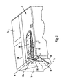
- Figs. 1 and 2 show a package 1 which is provided with an opening arrangement 10.
- This opening arrangement 10 comprises a bottom piece 11 which is secured around a hole in the packaging material, a lid 12 which, in the closed state, covers the hole in the packaging material and the bottom piece 11, as well as a pull tab 13 which, with its one end, is connected to the lid 12 and by means of which a consumer may open and close the lid 12.
- the pull tab 13 is, at its other end, connected to a tamper evidence 14 which in its turn is connected to a fixing surface 15. This fixing surface 15 is secured on the packaging material.
- the bottom piece 11 is secured on the top surface 1 a of the package 1 and the fixing surface is secured on a side surface 1b of the package.
- the package is designed so that the top surface 1a and the side surface 1b make a right angle in relation to one another.
- the present invention may be applied to other types of packages, such as, for example, so-called gable top packages and the like.
- the bottom piece is appropriately secured on one of the obliquely upwardly extending gable top surfaces and the fixing surface is secured on one of the side surfaces just beneath the transition between the gable top surface and the side surface.
- the gable top surface and the fixing surface make an angle of approximately 120°.
- top surfaces there are also variations of packages with obliquely inclined top surfaces where the present invention may be applied.
- the angle between the top surface and the side surface for such packages may, for example, vary between just under 90° to up to or just over 135°.
- the top surface makes an angle of 45° to the horizontal plane if the package is conventionally designed with a side surface which is at right angles to the bottom surface.
- packages have also evolved where one or more of the side surfaces are obliquely inclined in relation to the bottom surface.
- the above-mentioned angles will be somewhat smaller to a corresponding degree as the side surface slopes and if the side surface slopes inwards towards the interior of the package, the above-mentioned angles will be somewhat larger to a corresponding degree as the side surface slopes.
- packages should be taken into account which are provided with outwardly sloping side surfaces and horizontal or almost horizontal top surfaces.
- the right angle will be converted into an angle which is somewhat smaller; of the order of magnitude of approx. 70-80° or up towards 90° according as the side surface slopes.
- the package is formed so that the angle between the surfaces will be as good as a right angle.
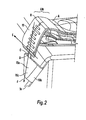
- a first portion 13a of the pull tab 13 to which the tamper evidence 14 is connected, the tamper evidence 14 and the fixing surface 15 extend along a common geometric plane 16 which is parallel with the side surface 1b of the package 1 and which abuts against the corner flap 1c folded towards the side surface 1b.
- this corner flap 1c is normally not present, but instead the pull tab 13, the tamper evidence 14 and the fixing surface 15 extend directly along the side surface (not shown).
- the pull tab 13 displays a second portion 13b via which the pull tab 13 is connected to the lid 12.
- Both of the portions 13a-b make an angle in relation to one another which is of the same order of magnitude as the angle between the top surface 1a and the side surface 1b. Further, the angle between the two portions 13a, 13b lies just outside the corner edge 1d, the top surface 1a and the side surface 1c and constitutes a substantial part of the curvature of the opening arrangement 10 which is needed in order that the bottom piece 11 and fixing surface 15 thereof be able to connect to two surfaces 1a, 1b which are angled in relation to one another.
- the opening arrangement 10 moreover displays a pouring edge 17 in order to facilitate pouring of the product filled into the package.
- a pouring edge 17 in order to facilitate pouring of the product filled into the package.
- two legs 18 which are intended to abut against the upper edge of the pouring aperture and keep the lid 12 in the open state.
- the opening arrangement 10 is applied according to one preferred embodiment on the packaging material before this has been ready-folded into a package.
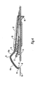
- Fig. 3 shows one method of realising a package with an opening arrangement according to the above-discussed type. For purposes of clarity, most components in the machine have been omitted and the only feature which is shown is how the packaging material is drawn through the filling machine in connection with production of a package.
- the packaging material is fed to the machine in the form of a magazine reel. First, a part of the reel is drawn up to a buffer zone 30 which is employed to take up changes in web length, among other things because of the fact that certain parts of the machine advance the web intermittently while others advance the web continuously.
- the buffer zone 30 is employed int. al.
- Similar buffer zones 31, 34, 35 are provided at several positions in the machine for similar purposes.
- the filling machine there are in addition three punches 32a-c which each punch a hole in the paper web.
- the paper web is of a width which is adapted so that it can be folded together into a package.
- the punches are disposed in sequence after one another in the direction of travel of the paper web and punch a pour aperture for each package.
- the web is advanced intermittently between strokes of the punches 32a-c.
- the method of indexing may vary between different types of machines. After one or a number of indexes forward, the packaging material with the punched holes arrives at an injection-moulding station.
- three opening arrangements 10 are injection-moulded direct on the web of packaging material.
- the paper web is clamped between two mould halves (one from each side of the web) which between them form a mould cavity.
- the mould cavity surrounds the hole punched in the packaging material, and the two halves of the mould cavity are in communication with one another by the intermediary of the hole punched in the packaging material.
- the packaging material is advanced by intermittent indexing.
- the material is formed into a tube in that its longitudinal edges are, in a conventional manner, sealed together (see portion 36 in Fig. 3 ).
- the tube is filled with the intended product and is divided up into individual packages in that the tube is transversely sealed (portion 37) and cut (portion 38) into cushion-shaped packaging blanks which are finally folded into packages in that corner flaps and the like are folded and fixed in the correct position (portion 39).
- Fig. 4 shows the shape which the opening arrangement 10 has when it has been injection-moulded or secured on the packaging material when this is in the planar or not completely folded state. Examples of situations involving not completely folded states are when the opening arrangement is applied to a system which employs blanks which are raised, sealed in one end, filled and finally sealed in the other end. A suitable occasion to apply the opening arrangement in such a system is then once the blank has been raised so that there is space to get at the inside of the package as well.
- the opening arrangement 10 disposed on the planar packaging material is folded so that the angle A between the lid 12 and the second portion 13b of the pull tab 13 is of the order of magnitude of 120°. In the finished state ( Fig. 1 and Fig. 2 ), this angle is of the order of magnitude of 180° (i.e. they extend in approximately the same line).
- the angle B between both portions 13a-b of the pull tab 13 is approximately 100°, and in the finished state, the angle B is approximately 90°. As was mentioned above, the angle B in the ready-folded state is different depending upon what form the finished package has.
- the angle B between the different portions 13a-b of the pull tab 13 is approximately the same as the angle in the fold 1d between the top surface 1a and the side surface 1b.
- the angle C between the first portion 13a of the pull tab 13 and the tamper evidence 14 is, in planar packaging material, approximately 100° and, in the finished state, it is approximately 180° so that the first portion 13a of the pull tab 13 and the tamper evidence 14 extend along the same plane 16.
- the angle D between the tamper evidence 14 and the fixing surface 15 is, in planar packaging material, approximately 90° and; in the finished state, it is approximately 180° so that the tamper evidence 14 and the fixing surface 15 extend along the same plane 16.
- the material at the angle A and B should only be folded a limited angle and, moreover, it may be formed without difficulty to withstand the loads which occur because of this folding.
- the material at the angle C and/or D should moreover be easy to tear off so that a consumer can rupture the tamper evidence 14 easily when the package 1 is to be opened for the first time.
- the illustrated configuration enjoys a number of advantages in relation to prior art configurations.
- the first portion 13a of the pull tab 13, the tamper evidence 14 proper and the fixing surface 15 extend along a common plane 16 which extends along the corner flap 1c of the package 1.
- the fixing surface 15 is formed and placed in such a manner on the package 1 that it is folded around a corner edge 1e of the corner flap 1c when the package is folded from a cushion-shaped body into a substantially brick-shaped package 1.
- This refolding of the fixing surface 15 around the corner edge 1e of the package 1 entails that the fixing surface 15 is secured on the package 1 and can absorb extreme loading compared with if it only extended along a planar portion of the package 1.
- Fig. 7 schematically shows how a fixing surface 15 is folded around a folded corner 1e of the package 1.
- the fixing surface 15 When the fixing surface 15 is loaded with a force along the above mentioned longitudinal direction F during distribution of the package 1, the inwardly folded portion 15b of the fixing surface 15 will need to be drawn around the corner 1e in order that the fixing surface 15 will come loose. Correspondingly, the fixing surface 15 will need to be drawn around the corner in order to loosen when a consumer ruptures the tamper evidence 14 for the first time.
- the oblique inclination of the corner edge 1e entails that, regardless of the angle the force has between the transverse direction and the longitudinal direction, the refolding 15b will need to be drawn around the corner 1e as long as the force on the fixing surface 15 is directed inwards towards the rest of the side surface 1b.
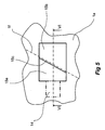
- Figs. 5-7 schematically show a fixing surface 15. That portion of the fixing surface 15 which is located most proximal the tamper evidence 14 and which is not folded around the corner edge 1e on the folding of the finished package displays a first thickness T1 which is greater than the thickness T2 of that portion 15b of the fixing surface 15 which is intended to be folded around the corner edge 1e of the corner flap 1c.
- the transition 15c between the thicker portion 15a and the thinner portion 15b is located along the line If along which the corner flap 1c is intended to be folded 1e. In the configuration illustrated in Fig. 5 and Fig. 6 , said line If is a crease line 1f.
- Fig. 6 schematically shows a type of packaging material which comprises an outer layer 2a of thermoplastic, a paper layer 2b, a barrier layer of aluminium 2c and an inner layer 2d of thermoplastic.
- the present invention is not restricted to this type of packaging material, but other materials with or without an aluminium layer may, for example, also be mentioned.
- the opening arrangement may be employed for packaging materials which do not include any paper layer at all. If the opening arrangement is manufactured by direct injection-moulding on the packaging material, it is, however, advantageous if the outer layer 2a (and most generally also the inner layer 2d) is of some form of thermoplastic whose surface melts slightly on the supply of molten plastic in the injection-moulding so that the opening arrangement is fused in position to the packaging material.
- the transition 15c between the thicker portion 15a and the thinner portion 15b will also contribute to a correct fusion against the packaging material since the plastic which is injected into the mould cavity via a nozzle somewhere on the lid 12 will be heated at the throttle 15c because of the inner friction so that the thinner portion 15b is fused against the packaging material.
- the thicker portion 15a is approximately hardly double as thick as the thinner portion 15b.
- the thicker portion 15a is of a thickness which lies within the range of 0.2 mm to approximately 1 mm and the thinner portion 15b has a thickness which lies in the range from 0.1 mm to up to 1 mm.
- the thicker portion 15a has a thickness T1 of 0.5 mm and the thinner portion 15b a thickness T2 of 0.3 mm.
- the opening arrangement 10 is formed in one piece of injection-moulded thermoplastic such as polyethylene or the like.
- thermoplastic such as polyethylene or the like.
- the transition between the lid 12 and the bottom piece 11 along the greater part of the pouring aperture is formed as a weakening along which a crack will propagate when the consumer opens the package for the first time.
- this weakening line of the lid 12 will be depressed down through the pouring aperture in the bottom piece 11 so that a collar 19 above the weakening seals against the defining edge of the pouring aperture.
- Fig. 7 shows how the packaging material 1 and the fixing surface 15 are folded for the formation of a corner edge 1e.
- the materials have not been completely folded, but the fold has merely been commenced. On complete folding, the insides of the packaging material abut against one another.
- the opening arrangement may be produced separately and thereafter secured on the packaging material on a planar web or as a wholly or partly folded package.
- the opening arrangement may be designed so that the bottom piece extends around the corner edge of the package between the top surface and the side surface, and that the fixing surface is secured in an extension of the bottom piece.
- the above discussed angle between the top surface and the side surface on which the fixing surface is secured relates to the angle seen along the fold line between the top surface and the side surface.
- packages are also conceivable where the side surface is obliquely inclined or has some other shape if the package is seen straight from above. This angle or shape does not, however, affect the tamper evidence and the fixing surface according to the present invention to any major extent.
- the method according to the present invention of securing the fixing surface may be employed for most types of opening arrangements.
- the fixing surface may be employed for securing a tamper evidence to a screw cap or the like.
Landscapes
- Engineering & Computer Science (AREA)
- Mechanical Engineering (AREA)
- Cartons (AREA)
- Injection Moulding Of Plastics Or The Like (AREA)
- Packages (AREA)
Description
- The present invention relates to a package produced by folding of a packaging material, the package being provided with an opening arrangement which comprises a bottom piece which is intended to define a pouring aperture, a lid which is disposed, in the closed state, to seal the pouring aperture, a tamper evidence which is intended to be ruptured the first time the opening arrangement is opened and which, on the one hand, is connected to the lid, and, on the other hand, connected to a fixing surface which is connected to the packaging material.
- The present invention further relates to a method of providing a package with an opening arrangement.
- There are innumerable ways of forming, folding and fusing together plastic film-coated paper material in order to produce packages for liquid foods, such as milk, juices and the like.
- One commercially viable method of producing a food package and filling it with a liquid food is shown in principle in
Fig. 1 . Apaper web 1 is formed continuously into a tube by bothlongitudinal edges 1a-b of the paper web being fused together, and thereafter the food in question is filled into the just formed tube. In the next process step, the tube is divided into packages in that it is transversely sealed and cut along the transverse seal so that there are formed cushion-shaped packaging blanks which are finally formed in that the corners are folded in and secured against the side surfaces of the package. One commercially well-known example of a package which is formed in this manner is the brick-shaped package Tetra Brik® produced by Tetra Pak. - The packaging material comprises at least one layer of paper and at least one layer of plastic. The plastic layer imparts to the paper layer the requisite resistance to moisture and is moreover intended to be partly fused for welding together different parts of the packaging material.
- In recent times, this type of package has been provided with different types of opening arrangements.
- For example,
US-A-4,725,213 discloses an opening arrangement of plastic which is injection-moulded direct in situ on a packaging material. A pair of mould halves are moved into engagement around a punched hole in the packaging material and a heated thermoplastic material is injected into the mould cavity and thereby forms an opening arrangement which covers the hole punched in the packaging material. The mould halves are formed so that the injection-moulded opening arrangement comprises two flanges extending around the circumference of the hole and abutting against opposing sides of the packaging material around the edge of the punched hole, the opening arrangement grasping about the edge of the hole and by such means sealing against the packaging material. -
US-B1-6,454,161 discloses yet a further variation of such an opening arrangement. This opening arrangement has moreover been provided with a tamper evidence which informs the consumer whether the package had been opened previously or not. In the illustrated embodiment, certain problems may however occur in connection with distribution, since the illustrated opening arrangement extends up from the upper side of the package. When a plurality of packages are stacked on one another, there is the risk that the tamper evidence is compressed together and damaged so that it is no longer unbroken even though the package has not been opened. If, in order to solve this problem, attempts are made to make the tamper evidence stronger the problem will however be encountered that the consumer finds it difficult to open the package for the first time when the tamper evidence is to be ruptured. -
US 2002/0148201 discloses an opening arrangement provided with a tamper evidence in the form of an tab which is formed integral with a cap. The tab spans from a gable portion of the carton to a front wall, where the tab end is molded to the carton. - A further problem which should be mentioned in this context is that certain configurations of opening arrangements suffer from the problem that the fixing surface to which the tamper evidence is fixed tends to come loose if it is exposed to severe loading on distribution or when a consumer intends to open the package for the first time.
- One object of the present invention is thus to realise package provided with an opening arrangement with a tamper evidence.
- A further object of the present invention is to realise package provided with an opening arrangement which is adapted so that, if desired, it may be injection-moulded direct over a hole in a packaging material.
- A further object of the present invention is to realise package provided with an opening arrangement which is provided with a fixing surface which can withstand severe loading without loosening.
- The above objects have been attained according to the present invention by means of package provided with an opening arrangement of the type described by way of introduction wherein a first portion of the pull tab, to which the tamper evidence is connected, the tamper evidence and the fixing surface extend over a common geometric plane, and in that the fixing surface extends over a fold line along which the packaging material and the fixing surface are double folded for the formation of a package. By such means, the fixing surface will need to be drawn around the corner in order to be able to be torn off, which purely geometrically makes it more difficult to pull loose the fixing surface from the package. Moreover, better use is made of the conventional packaging material of paper laminate. A paper-based packaging laminate usually has greater resistance to delamination in connection with shearing between the layers as compared with separation of the layers in the normal direction.
- Preferred embodiments of the present invention are further apparent from the appended subclaims.
- According to one preferred embodiment, that portion of the fixing surface which is intended to be located on the same side of the fold line as the bottom piece has a thickness which is greater than the thickness of that portion of the fixing surface which is intended to be located on the other side of the fold line. By such means, it is possible to realise a stable fixing surface which gives stability in connection with the tamper evidence. Moreover, the thinner portion is easier to fold in connection with the package being folded. In connection which injection-moulding of an opening arrangement of this type, the throttle between the thicker and the thinner portion entails that friction heat will be generated which contributes in ensuring that the entire mould cavity is filled.
- Advantageously, the opening arrangement is of one piece manufacture, preferably by injection-moulding of a polymer, such as a thermoplastic. By such means, it is possible to realise in a cost effective manner an opening arrangement displaying a plurality of functional features. Moreover, this technique is possible to be employed for most types of packaging systems.
- According to one preferred embodiment, the lid and the bottom piece are formed in the closed state, the connection between the lid and the bottom piece around the greater part of the pouring aperture including a weakening line which is intended to be broken the first time the opening arrangement is opened. By such means, there will be realised an opening arrangement which is liquid-tight immediately after forming and which, after the first opening, may be reclosed, for example, in that the portion of the lid which supports the weakening line is depressed down into the pouring aperture.
- Advantageously, the opening arrangement is of one piece manufacture, preferably by injection-moulding of a polymer, such as a thermoplastic, direct on the packaging material. By such means, it is relatively simple to provide packages from the above mentioned continuously web-fed system with opening arrangements. Preferably, holes are punched and the opening arrangement is formed directly over the hole in the filling machine.
- The above objects have also been attained by means of a package of the type described by way of introduction which has been given the characterising features that the fixing surface extends over a fold line along which the packaging material and the fixing surface are double folded for forming a package. As was discussed in-depth above, this gives a number of advantages as regards the mechanical strength of the package. The fixing surface will need to be drawn around the corner in order to be able to be torn off, with the result that purely geometrically it becomes more difficult to pull loose the fixing surface from the package. Moreover, better use is made of the conventional packaging material of paper laminate. A paper-based packaging laminate normally displays greater resistance to delamination in connection with shearing between the layers as compared with separation of the layers in the normal direction.
- Preferred embodiments of the present invention are apparent from the appended subclaims. Advantages relating to these features will be apparent from the above explanations relating to corresponding features in connection with the opening arrangement.
- The above objects have also been attained according to the present invention by means of a method of providing a package with an opening arrangement, comprising the steps of realising an opening arrangement which comprises a bottom piece, a lid collapsible about a fold pivot, a tamper evidence which is intended to be ruptured the first time the opening arrangement is opened and which, on the one hand, is connected to the lid and, on the other hand, connected to a fixing surface, securing the opening arrangement on a packaging material, and securing the fixing surface so that it extends over a fold line along which the packaging material and the fixing surface are intended to be double folded for forming a package.
- As was discussed in-depth above, this affords a number of advantages as regards the mechanical strength of the package. The fixing surface will need to be drawn around the corner in order to be able to be torn off, with the result that purely geometrically it will be more difficult to pull loose the fixing surface from the package. Moreover, better use is made of the conventional packaging material of paper laminate. A paper-based packaging laminate normally displays greater resistance to delamination in connection with shearing between the layers as compared with separation of the layers in the normal direction.
- Preferred embodiments of the present invention are apparent from the appended subclaims.
- According to one preferred embodiment, the folding of the packaging material takes place so that the fixing surface is folded double. This reinforces the mechanical strength of the securement of the fixing surface. Further, the folding double entails that the fixing surface must release from the packaging material in a direction which is opposite to the drawing direction of the outermost edge of the fixing surface.
- Advantageously, said method includes the steps of punching a hole in a packaging material, and securing the opening arrangement over the hole. By such means, it is possible to realise a package which is simple to open and which, in many cases, may also be reclosed.
- According to one preferred embodiment, said method further comprises the steps of closing, by means of a moulding tool, a mould cavity around the hole in the packaging material, of injection-moulding in one piece an opening arrangement comprising a bottom piece, a collapsible lid, a pull tab, a tamper evidence as well as a fixing surface, and securing, in the injection-moulding operation, the bottom piece and the fixing surface to the packaging material. By such means, it is possible to provide packages with opening arrangements as good as regardless of the system which is employed for forming and filling the packages.. The technique may be employed for so-called roll-fed systems and for so-called blank-fed systems.
- According to one preferred embodiment, said method further comprises the step of folding the packaging material for the formation of a package along a line which extends transversely of a line defined by the pull tab, the tamper evidence and the fixing surface. The thus produced package with the opening arrangement is designed so that the consumer ruptures the tamper evidence by applying a force in a transverse direction in relation to that direction along which the pull tab, the tamper evidence and the fixing surface extend. By such means, the possibility has been created of separating the direction in which the tamper evidence is placed under load during manufacture and distribution in relation to the direction which is placed under load when the consumer opens the package for the first time. This entails that it is possible to form the tamper evidence so that it will be strong on distribution loading, but at the same time it is possible to provide it with a clear tear indication facilitating access for the consumer. By folding the opening arrangement and the package, the tamper evidence is to some degree concealed from those forces which would otherwise cause it to fail when several layers of packages are stacked on one another. Moreover, it will be easier for a consumer to naturally grip the package and pull off the tamper evidence. A consumer usually grasps the package around the upright rear side of the package with the opening arrangement uppermost on the package. Since the tamper evidence extends around the corner edge and down on the narrow front side, it is easy to get at the tamper evidence with the free hand without needing to angle the package or the free hand in any unusual angle. Moreover, the natural gripping direction will entail that the consumer (while not correctly understanding the direction in which the tamper evidence is to be torn) can apply a force with a certain composant in the transverse direction, which ensures that correct tearing-off of the tamper evidence will take place.
- In order to facilitate the folding, it is advantageous to provide the packaging material with a crease line, the bottom surface and the fixing surface being secured on either side of the crease line.
- According to one preferred embodiment, the packaging material is web-shaped when injection-moulding of the opening arrangement takes place on the packaging material, which makes it easier to get at the material from both sides.
- Advantageously, the pull tab and the tamper evidence form, after injection-moulding on the packaging material, an arc which extends between the lid and the fixing surface, which facilitates for the pull tab and the tamper evidence to be folded in connection with the folding of the package.
- The present invention will now be described in greater detail hereinbelow, with reference to the accompanying schematic Drawings which, for purposes of exemplification, show one currently preferred embodiment of the present invention. In the accompanying Drawings:
-
Fig. 1 shows in perspective an upper portion of a brick-shaped package provided with an opening arrangement; -
Fig. 2 shows a part ofFig. 1 on a larger scale; -
Fig. 3 schematically shows one example of how a material web of packaging material may be drawn through and treated by a filling machine for realising a package of the type illustrated inFig. 1 ; -
Fig. 4 shows an opening arrangement seen from the side; -
Fig. 5 schematically illustrates the fixing surface seen straight from above; -
Fig. 6 schematically illustrates the packaging material and the fixing surface secured on the packaging material seen from the side; and -
Fig. 7 schematically shows how the packaging material and the fixing surface secured on the packaging material are disposed to be folded for the formation of the package illustrated inFig. 1 . -
Figs. 1 and2 show apackage 1 which is provided with anopening arrangement 10. Thisopening arrangement 10 comprises a bottom piece 11 which is secured around a hole in the packaging material, alid 12 which, in the closed state, covers the hole in the packaging material and the bottom piece 11, as well as apull tab 13 which, with its one end, is connected to thelid 12 and by means of which a consumer may open and close thelid 12. Thepull tab 13 is, at its other end, connected to atamper evidence 14 which in its turn is connected to a fixingsurface 15. This fixingsurface 15 is secured on the packaging material. - The bottom piece 11 is secured on the
top surface 1 a of thepackage 1 and the fixing surface is secured on aside surface 1b of the package. In the embodiment illustrated inFig. 1 , the package is designed so that thetop surface 1a and theside surface 1b make a right angle in relation to one another. Naturally, the present invention may be applied to other types of packages, such as, for example, so-called gable top packages and the like. In such an event, the bottom piece is appropriately secured on one of the obliquely upwardly extending gable top surfaces and the fixing surface is secured on one of the side surfaces just beneath the transition between the gable top surface and the side surface. For a conventional gable top package, the gable top surface and the fixing surface make an angle of approximately 120°. There are also variations of packages with obliquely inclined top surfaces where the present invention may be applied. The angle between the top surface and the side surface for such packages, may, for example, vary between just under 90° to up to or just over 135°. At 135° between the side surface and the top surface, the top surface makes an angle of 45° to the horizontal plane if the package is conventionally designed with a side surface which is at right angles to the bottom surface. In recent times, packages have also evolved where one or more of the side surfaces are obliquely inclined in relation to the bottom surface. In those cases where the side surface slopes outwards from the package, the above-mentioned angles will be somewhat smaller to a corresponding degree as the side surface slopes and if the side surface slopes inwards towards the interior of the package, the above-mentioned angles will be somewhat larger to a corresponding degree as the side surface slopes. Above all, packages should be taken into account which are provided with outwardly sloping side surfaces and horizontal or almost horizontal top surfaces. In such an event, the right angle will be converted into an angle which is somewhat smaller; of the order of magnitude of approx. 70-80° or up towards 90° according as the side surface slopes. For packages with outwardly sloping side surfaces and oblique top surfaces, it is probable that the package is formed so that the angle between the surfaces will be as good as a right angle. - As is apparent from
Fig. 1 , afirst portion 13a of thepull tab 13 to which thetamper evidence 14 is connected, thetamper evidence 14 and the fixingsurface 15 extend along a commongeometric plane 16 which is parallel with theside surface 1b of thepackage 1 and which abuts against thecorner flap 1c folded towards theside surface 1b. For a so-called gable top package, thiscorner flap 1c is normally not present, but instead thepull tab 13, thetamper evidence 14 and the fixingsurface 15 extend directly along the side surface (not shown). Moreover, thepull tab 13 displays asecond portion 13b via which thepull tab 13 is connected to thelid 12. Both of theportions 13a-b make an angle in relation to one another which is of the same order of magnitude as the angle between thetop surface 1a and theside surface 1b. Further, the angle between the twoportions corner edge 1d, thetop surface 1a and theside surface 1c and constitutes a substantial part of the curvature of theopening arrangement 10 which is needed in order that the bottom piece 11 and fixingsurface 15 thereof be able to connect to twosurfaces - As is apparent from
Fig. 4 , theopening arrangement 10 moreover displays a pouring edge 17 in order to facilitate pouring of the product filled into the package. InFig. 4 , there are also shown twolegs 18 which are intended to abut against the upper edge of the pouring aperture and keep thelid 12 in the open state. These components may be formed in innumerable different ways. - The
opening arrangement 10 is applied according to one preferred embodiment on the packaging material before this has been ready-folded into a package.Fig. 3 shows one method of realising a package with an opening arrangement according to the above-discussed type. For purposes of clarity, most components in the machine have been omitted and the only feature which is shown is how the packaging material is drawn through the filling machine in connection with production of a package. The packaging material is fed to the machine in the form of a magazine reel. First, a part of the reel is drawn up to abuffer zone 30 which is employed to take up changes in web length, among other things because of the fact that certain parts of the machine advance the web intermittently while others advance the web continuously. Thebuffer zone 30 is employed int. al. to make possible automatic reel change without the machine needing to be stopped.Similar buffer zones punches 32a-c which each punch a hole in the paper web. The paper web is of a width which is adapted so that it can be folded together into a package. The punches are disposed in sequence after one another in the direction of travel of the paper web and punch a pour aperture for each package. Along this part of the machine, the web is advanced intermittently between strokes of thepunches 32a-c. The method of indexing may vary between different types of machines. After one or a number of indexes forward, the packaging material with the punched holes arrives at an injection-moulding station. In this station, three openingarrangements 10 are injection-moulded direct on the web of packaging material. The paper web is clamped between two mould halves (one from each side of the web) which between them form a mould cavity. The mould cavity surrounds the hole punched in the packaging material, and the two halves of the mould cavity are in communication with one another by the intermediary of the hole punched in the packaging material. Also in this part of the machine, the packaging material is advanced by intermittent indexing. - Once the packaging material has been provided with opening
arrangements 10, the material is formed into a tube in that its longitudinal edges are, in a conventional manner, sealed together (seeportion 36 inFig. 3 ). The tube is filled with the intended product and is divided up into individual packages in that the tube is transversely sealed (portion 37) and cut (portion 38) into cushion-shaped packaging blanks which are finally folded into packages in that corner flaps and the like are folded and fixed in the correct position (portion 39). - This method of providing a package with an opening arrangement is per se known in the art and will not be described in greater detail, but for a technical description reference is made, for example, to
US-A-6,3,03,066 andEP-A1-1160172 . -
Fig. 4 shows the shape which theopening arrangement 10 has when it has been injection-moulded or secured on the packaging material when this is in the planar or not completely folded state. Examples of situations involving not completely folded states are when the opening arrangement is applied to a system which employs blanks which are raised, sealed in one end, filled and finally sealed in the other end. A suitable occasion to apply the opening arrangement in such a system is then once the blank has been raised so that there is space to get at the inside of the package as well. - The
opening arrangement 10 disposed on the planar packaging material is folded so that the angle A between thelid 12 and thesecond portion 13b of thepull tab 13 is of the order of magnitude of 120°. In the finished state (Fig. 1 andFig. 2 ), this angle is of the order of magnitude of 180° (i.e. they extend in approximately the same line). On planar packaging material (Fig. 4 ), the angle B between bothportions 13a-b of thepull tab 13 is approximately 100°, and in the finished state, the angle B is approximately 90°. As was mentioned above, the angle B in the ready-folded state is different depending upon what form the finished package has. The angle B between thedifferent portions 13a-b of thepull tab 13 is approximately the same as the angle in thefold 1d between thetop surface 1a and theside surface 1b. The angle C between thefirst portion 13a of thepull tab 13 and thetamper evidence 14 is, in planar packaging material, approximately 100° and, in the finished state, it is approximately 180° so that thefirst portion 13a of thepull tab 13 and thetamper evidence 14 extend along thesame plane 16. The angle D between thetamper evidence 14 and the fixingsurface 15 is, in planar packaging material, approximately 90° and; in the finished state, it is approximately 180° so that thetamper evidence 14 and the fixingsurface 15 extend along thesame plane 16. - The material at the angle A and B should only be folded a limited angle and, moreover, it may be formed without difficulty to withstand the loads which occur because of this folding. On the other hand, the material at the angle C and/or D should moreover be easy to tear off so that a consumer can rupture the
tamper evidence 14 easily when thepackage 1 is to be opened for the first time. As was mentioned above, the illustrated configuration enjoys a number of advantages in relation to prior art configurations. Since a consumer tears thetamper evidence 14 by applying a force on thefirst portion 13a of thepull tab 13 in a direction which extends along a transverse direction E transversely of the longitudinal direction F which is defined by thefirst portion 13a of thepull tab 13, thetamper evidence 14 proper and the fixingsurface 15, it is possible to form the connections of thetamper evidence 14 to thepull tab 13 and the fixingsurface 15 so that they are strong in the longitudinal direction F but weak in the transverse direction E. By such means, anopening arrangement 10 has been realised which is adapted to be manufactured in the manner which is apparent fromFig. 3 and which nevertheless gives the desiredtamper evidence 14. As is apparent fromFig. 1 andFig. 2 , thefirst portion 13a of thepull tab 13, thetamper evidence 14 proper and the fixingsurface 15 extend along acommon plane 16 which extends along thecorner flap 1c of thepackage 1. By such means, there is no edge which may catch in a corner or the like on a package placed adjacent the illustrated package. - As is apparent from
Fig. 1 andFig. 2 , the fixingsurface 15 is formed and placed in such a manner on thepackage 1 that it is folded around acorner edge 1e of thecorner flap 1c when the package is folded from a cushion-shaped body into a substantially brick-shapedpackage 1. This refolding of the fixingsurface 15 around thecorner edge 1e of thepackage 1 entails that the fixingsurface 15 is secured on thepackage 1 and can absorb extreme loading compared with if it only extended along a planar portion of thepackage 1.Fig. 7 schematically shows how a fixingsurface 15 is folded around a foldedcorner 1e of thepackage 1. When the fixingsurface 15 is loaded with a force along the above mentioned longitudinal direction F during distribution of thepackage 1, the inwardly foldedportion 15b of the fixingsurface 15 will need to be drawn around thecorner 1e in order that the fixingsurface 15 will come loose. Correspondingly, the fixingsurface 15 will need to be drawn around the corner in order to loosen when a consumer ruptures thetamper evidence 14 for the first time. One advantage inherent in the fact that the fixingsurface 15 is folded around thecorner edge 1e of thecorner flap 1c as shown inFig. 1 andFig. 2 is that the oblique inclination of thecorner edge 1e entails that, regardless of the angle the force has between the transverse direction and the longitudinal direction, therefolding 15b will need to be drawn around thecorner 1e as long as the force on the fixingsurface 15 is directed inwards towards the rest of theside surface 1b. -
Figs. 5-7 schematically show a fixingsurface 15. That portion of the fixingsurface 15 which is located most proximal thetamper evidence 14 and which is not folded around thecorner edge 1e on the folding of the finished package displays a first thickness T1 which is greater than the thickness T2 of thatportion 15b of the fixingsurface 15 which is intended to be folded around thecorner edge 1e of thecorner flap 1c. Thetransition 15c between thethicker portion 15a and thethinner portion 15b is located along the line If along which thecorner flap 1c is intended to be folded 1e. In the configuration illustrated inFig. 5 andFig. 6 , said line If is acrease line 1f. -
Fig. 6 schematically shows a type of packaging material which comprises anouter layer 2a of thermoplastic, apaper layer 2b, a barrier layer ofaluminium 2c and aninner layer 2d of thermoplastic. The present invention is not restricted to this type of packaging material, but other materials with or without an aluminium layer may, for example, also be mentioned. Further, the opening arrangement may be employed for packaging materials which do not include any paper layer at all. If the opening arrangement is manufactured by direct injection-moulding on the packaging material, it is, however, advantageous if theouter layer 2a (and most generally also theinner layer 2d) is of some form of thermoplastic whose surface melts slightly on the supply of molten plastic in the injection-moulding so that the opening arrangement is fused in position to the packaging material. - The
transition 15c between thethicker portion 15a and thethinner portion 15b will also contribute to a correct fusion against the packaging material since the plastic which is injected into the mould cavity via a nozzle somewhere on thelid 12 will be heated at thethrottle 15c because of the inner friction so that thethinner portion 15b is fused against the packaging material. According to one preferred embodiment, thethicker portion 15a is approximately hardly double as thick as thethinner portion 15b. Thethicker portion 15a is of a thickness which lies within the range of 0.2 mm to approximately 1 mm and thethinner portion 15b has a thickness which lies in the range from 0.1 mm to up to 1 mm. According to one preferred embodiment, thethicker portion 15a has a thickness T1 of 0.5 mm and thethinner portion 15b a thickness T2 of 0.3 mm. - According to one embodiment, the
opening arrangement 10 is formed in one piece of injection-moulded thermoplastic such as polyethylene or the like. In such a configuration, it is appropriate to form the bottom piece 11 and thelid 12 in the closed state so that they are formed to a continuous body which wholly and completely surrounds the above mentioned hole in the packaging material. In order that the consumer be able to open the package, the transition between thelid 12 and the bottom piece 11 along the greater part of the pouring aperture is formed as a weakening along which a crack will propagate when the consumer opens the package for the first time. When the consumer closes the package after having emptied a part of the product out of the package, this weakening line of thelid 12 will be depressed down through the pouring aperture in the bottom piece 11 so that acollar 19 above the weakening seals against the defining edge of the pouring aperture. -
Fig. 7 shows how thepackaging material 1 and the fixingsurface 15 are folded for the formation of acorner edge 1e. InFig. 7 , the materials have not been completely folded, but the fold has merely been commenced. On complete folding, the insides of the packaging material abut against one another. - It will be readily perceived by a person skilled in the art that a number of modifications of the embodiments of the present invention described herein are possible without departing from the scope of the invention as this is defined in the appended Claims.
- For example, the opening arrangement may be produced separately and thereafter secured on the packaging material on a planar web or as a wholly or partly folded package.
- Further, the opening arrangement may be designed so that the bottom piece extends around the corner edge of the package between the top surface and the side surface, and that the fixing surface is secured in an extension of the bottom piece.
- It might also be mentioned that the above discussed angle between the top surface and the side surface on which the fixing surface is secured relates to the angle seen along the fold line between the top surface and the side surface. Naturally, packages are also conceivable where the side surface is obliquely inclined or has some other shape if the package is seen straight from above. This angle or shape does not, however, affect the tamper evidence and the fixing surface according to the present invention to any major extent.
- Naturally, the method according to the present invention of securing the fixing surface may be employed for most types of opening arrangements. For example, the fixing surface may be employed for securing a tamper evidence to a screw cap or the like.
Claims (17)
- A package produced by folding of a packaging material (1) which is provided with an opening arrangement (10) which comprises a bottom piece (11) which is intended to define a pouring aperture, a lid (12) which is disposed, in the closed state, to seal the pouring aperture, a tamper evidence (14) which is intended to be ruptured the first time the opening arrangement (10) is opened and which, on the one hand, is connected to the lid (12) and, on the other hand, connected to a fixing surface (15) which is connected to the packaging material (1), and a first portion (13a) of the pull tab (13), to which the tamper evidence (14) is connected, the tamper evidence (14) and the fixing surface (15) extend along a common geometric plane (16), characterised in that the fixing surface (15) extends over a fold line (1e) along which the packaging material (1) and the fixing surface (15) are double folded for forming a package.
- The package as claimed in Claim 1, wherein that portion (15a) of the fixing surface (15) which is located on the same side of the fold line (1e) as the bottom piece (11) is of a thickness (T1) which is greater than the thickness (T2) of that portion (15b) of the fixing surface (15) which is located on the other side of the fold line (1e).
- The package as claimed in Claim 1 or 2, wherein said fold line (1e) over which the fixing surface (15) extends is formed as a crease line.
- The package as claimed in anyone or more of Claims 1 or 2, wherein the opening arrangement (10) is of one piece manufacture, preferably by injection-moulding of a polymer, such as a thermoplastic.
- The package as claimed in Claim 4, wherein the lid (12) and the bottom piece (11) area formed in the closed state, the connection between the lid (12) and the bottom piece (11), around a greater part of the pouring aperture, comprising a weakening line which is intended to be broken the first time the opening arrangement (10) is opened.
- The package as claimed in Claim 4, wherein the opening arrangement (10) is of one piece manufacture, preferably by injection-moulding of a polymer, such as a thermoplastic, direct on the packaging material (1).
- The package as claimed in Claim 1, wherein the packaging material (1) is, for forming a package, folded along a line (1d, E) which extends transversely of a line (F) which is defined by the bottom piece (11), the tamper evidence (14) and the fixing surface (15).
- The package as claimed in Claim 1, wherein the packaging material (1) is provided with a crease line (1d), the bottom surface (11) and the fixing surface (15) being secured on either side of the crease line (1f).
- A method of providing a package with an opening arrangement (10), comprising the steps of:realising an opening arrangement (10) which comprises a bottom piece (11), a lid (12) collapsible about a fold pivot, a tamper evidence (14) which is intended to be ruptured the first time the opening arrangement (10) is opened and which, on the one hand, is connected to the lid (12) and, on the other hand, connected to a fixing surface (15),securing the opening arrangement (10) on a packaging material (1),disposing the opening arrangement (10) such that a first portion (13a) of the pull tab (13), to which the tamper evidence (14) is connected, the tamper evidence (14) and the fixing surface (15), after folding of the package, extend along a common geometric plane (16), andsecuring the fixing surface (15) so that it extends over a fold line (1e) along which the packaging material (1) and the fixing surface (15) are double folded for the formation of a package.
- The method as claimed in Claim 9, which further comprises the step of folding the packaging material (1) into a package so that the fixing surface (15) is folded about said fold line (1e).
- The method as claimed in Claim 9, further comprising the steps of punching (32a-d) a hole in the packaging material (1) and securing the opening arrangement (10) over the hole.
- The method as claimed in Claim 9, further comprising the steps of closing, by means of a moulding tool (33a-c) a mould cavity about the hole in the packaging material (1),
injection-moulding in one piece an opening arrangement (10) comprising a bottom piece (11), a collapsible lid (12), a pull tab (13), a tamper evidence (14) as well as a fixing surface (15), and
securing, in the injection-moulding, the bottom piece (11) and the fixing surface (15) to the packaging material (1). - The method as claimed in Claim 9, further comprising the step of folding the packaging material (1) for forming a package along a line (1d, E) which extends transversely of a line (F) which is defined by the pull tab (13), the tamper evidence (14) and the fixing surface (15).
- The method as claimed in Claim 9, further comprising the step of providing the packaging material (1) with a crease line (1d), the bottom surface 811) and the fixing surface (15) being secured on either side of the crease line (1d).
- The method as claimed in Claim 13, wherein the packaging material (1) is web-shaped when the injection-moulding of the opening arrangement (10) takes place on the packaging material (1).
- The method as claimed in Claim 9, further comprising the step of forming the packaging material (1) into a tube by joining together two longitudinal edges of the packaging material.
- The method as claimed in Claim 9, wherein the pull tab (13) and the tamper evidence (14) form, after injection-moulding on the packaging material (1), an arc which extends between the lid (12) and the fixing surface (15).
Applications Claiming Priority (3)
| Application Number | Priority Date | Filing Date | Title |
|---|---|---|---|
| SE0203617A SE525597C2 (en) | 2002-12-06 | 2002-12-06 | Opening device packaging and ways of providing a package with an opening device |
| SE0203617 | 2002-12-06 | ||
| PCT/SE2003/001794 WO2004052737A1 (en) | 2002-12-06 | 2003-11-19 | An opening arrangement, a package, as well as a method of providing a package with an opening arrangement |
Publications (2)
| Publication Number | Publication Date |
|---|---|
| EP1585677A1 EP1585677A1 (en) | 2005-10-19 |
| EP1585677B1 true EP1585677B1 (en) | 2009-03-18 |
Family
ID=20289784
Family Applications (1)
| Application Number | Title | Priority Date | Filing Date |
|---|---|---|---|
| EP03773021A Expired - Lifetime EP1585677B1 (en) | 2002-12-06 | 2003-11-19 | Package withan opening arrangement and method of providing a package with an opening arrangement |
Country Status (14)
| Country | Link |
|---|---|
| US (1) | US7191931B2 (en) |
| EP (1) | EP1585677B1 (en) |
| JP (1) | JP4242350B2 (en) |
| CN (1) | CN100584703C (en) |
| AT (2) | AT7866U1 (en) |
| AU (1) | AU2003279682B2 (en) |
| BR (1) | BR0314983B1 (en) |
| DE (2) | DE20303386U1 (en) |
| ES (1) | ES2322703T3 (en) |
| MX (1) | MXPA05003794A (en) |
| PT (1) | PT1585677E (en) |
| RU (1) | RU2329185C2 (en) |
| SE (1) | SE525597C2 (en) |
| WO (1) | WO2004052737A1 (en) |
Families Citing this family (18)
| Publication number | Priority date | Publication date | Assignee | Title |
|---|---|---|---|---|
| ES2305371T3 (en) | 2002-06-26 | 2008-11-01 | Avery Dennison Corporation | POLYMERIC FILMS ORIENTED IN THE DIRECTION OF MACHINING. |
| US8083089B2 (en) * | 2005-07-13 | 2011-12-27 | Pwp Industries Inc. | Versatile tamper-evident food container |
| US8251242B2 (en) * | 2005-06-10 | 2012-08-28 | Pwp Industries | Tamper-evident container with extended band |
| US7631776B2 (en) * | 2005-06-10 | 2009-12-15 | Pwp Industries | Tamper evident container with tear-apart parts |
| ITTO20060298A1 (en) * | 2006-04-21 | 2007-10-22 | Tetra Laval Holdings & Finance | UNIT AND METHOD FOR THE PREPARATION OF AN OPENING DEVICE ON BONDING ON A RESPECTIVE SEALED PACKAGE CONTAINING A VERSABLE FOOD PRODUCT |
| EP2049333B1 (en) | 2006-06-14 | 2012-12-05 | Avery Dennison Corporation | Conformable and die-cuttable machine direction oriented labelstocks and labels, and process for preparing |
| CN101484315B (en) | 2006-06-20 | 2013-04-10 | 艾利丹尼森公司 | Multilayered polymeric film for hot melt adhesive labeling and label stock and label thereof |
| WO2008024774A2 (en) * | 2006-08-21 | 2008-02-28 | Tropicana Products, Inc. | Container having improved pouring characteristics |
| US20090206082A1 (en) * | 2008-02-14 | 2009-08-20 | Pwp Industries | Tamper-evident packaging system |
| EP2393717A4 (en) * | 2009-02-06 | 2013-08-14 | Univ Northwestern | PACKAGING LIQUID THAT CAN EXPLODE AND USES THEREOF |
| JP5486753B2 (en) * | 2009-11-30 | 2014-05-07 | 日本テトラパック株式会社 | Packaging container manufacturing method, spout stopper and packaging container |
| GB201205243D0 (en) | 2012-03-26 | 2012-05-09 | Kraft Foods R & D Inc | Packaging and method of opening |
| US9676532B2 (en) | 2012-08-15 | 2017-06-13 | Avery Dennison Corporation | Packaging reclosure label for high alcohol content products |
| PL2885215T3 (en) * | 2012-08-15 | 2019-04-30 | Avery Dennison Corp | Packaging reclosure label for high alcohol content products |
| GB2511559B (en) | 2013-03-07 | 2018-11-14 | Mondelez Uk R&D Ltd | Improved Packaging and Method of Forming Packaging |
| GB2511560B (en) | 2013-03-07 | 2018-11-14 | Mondelez Uk R&D Ltd | Improved Packaging and Method of Forming Packaging |
| EP2889231A1 (en) * | 2013-12-30 | 2015-07-01 | Tetra Laval Holdings & Finance SA | Packaging material and packaging container having an opening device made therefrom |
| US11459488B2 (en) | 2014-06-02 | 2022-10-04 | Avery Dennison Corporation | Films with enhanced scuff resistance, clarity, and conformability |
Family Cites Families (47)
| Publication number | Priority date | Publication date | Assignee | Title |
|---|---|---|---|---|
| CH415441A (en) | 1964-03-20 | 1966-06-15 | Tepar Ag | Device on square capsule packaging for opening and emptying the same |
| US3450458A (en) * | 1966-05-27 | 1969-06-17 | Stanley G Potrzuski | Field specimen microscope |
| US3604596A (en) * | 1969-01-17 | 1971-09-14 | Continental Can Co | Tamper-indicating closures |
| SE332386C (en) | 1969-10-20 | 1972-05-23 | Tetra Pak Int | Opening device for packaging |
| SE324535B (en) | 1969-11-14 | 1970-06-01 | Tetra Pak Ab | |
| CH557268A (en) | 1972-10-18 | 1974-12-31 | Rausing Anders Ruben | DISPOSABLE PACKAGING CONTAINERS. |
| CH562135A5 (en) | 1973-02-20 | 1975-05-30 | Tetra Pak Dev | |
| US3977591A (en) | 1974-06-28 | 1976-08-31 | Ab Ziristor | Cover strip for the pouring opening in a packing container |
| FR2310283A1 (en) | 1975-05-09 | 1976-12-03 | Altstaedter Verpack Vertrieb | TEAR-OPEN PACKAGING FOR LIQUIDS |
| SE412044B (en) | 1976-07-08 | 1980-02-18 | Ziristor Ab | PACKAGING CONTAINER OPENING DEVICE |
| SE422672B (en) * | 1976-07-08 | 1982-03-22 | Ziristor Ab | WITH OPENING DEVICE PROVIDED PACKAGING CONTAINER |
| GB1555748A (en) | 1977-09-01 | 1979-11-14 | Tetra Pak Int | Opening of containers |
| DE2758092C2 (en) * | 1977-12-24 | 1983-07-21 | Altstädter Verpackungs-Vertriebsgesellschaft mbH, 6102 Pfungstadt | Opening device for a package made of flexible material |
| US4312450A (en) | 1978-02-14 | 1982-01-26 | Tetra Pak Development S.A. | Opening means for packaging containers |
| CH627700A5 (en) | 1978-04-17 | 1982-01-29 | Tetra Pak Dev | RE-CLOSABLE OPENING DEVICE IN A WALL OF A PACKAGING CONTAINER, AND METHOD FOR THE PRODUCTION THEREOF. |
| SE439452B (en) | 1983-12-15 | 1985-06-17 | Tetra Pak Int | SET TO SEAL AN EMPTY OPENING AND DEVICE IMPLEMENTATION DEVICE |
| SE8401616D0 (en) | 1984-03-23 | 1984-03-23 | Tetra Pak Int | WRAPPING CONTAINER FOR PACKAGING CONTAINERS AND WAY TO MANUFACTURE THEM |
| DE3513976A1 (en) | 1985-04-18 | 1986-10-30 | Tetra Pak International AB, Lund | LIQUID PACKING AND METHOD AND DEVICE FOR PRODUCING THE SAME |
| SE454685B (en) | 1985-06-12 | 1988-05-24 | Tetra Pak Ab | PACKAGING CONTAINER OPENING DEVICE |
| SE451012B (en) * | 1985-09-20 | 1987-08-24 | Tetra Pak Ab | RELEASABLE OPENING DEVICE BY A PACKAGING CONTAINER AND WAY TO MANUFACTURE IT |
| DE3606280A1 (en) | 1986-02-27 | 1987-09-03 | Altstaedter Verpack Vertrieb | LOCKING DEVICE FOR A SYRINGE DEVICE |
| US4770325A (en) | 1986-07-29 | 1988-09-13 | International Paper Company | Pour spout for containers |
| SE500540C2 (en) * | 1988-11-09 | 1994-07-11 | Roby Teknik Ab | Opening device at a packaging container |
| SE462745B (en) | 1988-12-16 | 1990-08-27 | Profor Ab | MOVE TO CONNECT A GRIP ORGAN WITH A SHEET OR TRAFFIC PACKAGING MATERIAL |
| SE8900792L (en) * | 1989-03-07 | 1990-09-08 | Roby Teknik Ab | WITH OPENING DEVICE PROVIDED PACKAGING CONTAINER |
| JPH0752345B2 (en) * | 1989-03-30 | 1995-06-05 | ヤマハ株式会社 | Initial touch controller |
| US5108029A (en) * | 1990-02-16 | 1992-04-28 | Capitol Spouts, Inc. | Reclosable attachment for containers |
| JPH0627542Y2 (en) | 1990-02-28 | 1994-07-27 | 日本製紙株式会社 | Closed paper container with opening device |
| JPH0551032A (en) * | 1991-08-15 | 1993-03-02 | Dainippon Printing Co Ltd | Paper container |
| SE9200391L (en) | 1992-02-11 | 1993-08-12 | Tetra Laval Holdings & Finance | Opening device |
| SE501329C2 (en) | 1993-12-17 | 1995-01-16 | Tetra Laval Holdings & Finance | Opening device for liquid packaging |
| US5772060A (en) | 1994-11-29 | 1998-06-30 | Tetra Laval Holdings & Finance S.A. | Pull-tab for a liquid container |
| DE19544601A1 (en) | 1995-11-30 | 1997-06-05 | Tetra Laval Holdings & Finance | Packet for free-flowing contents, with pourer and closure piece on hole in top |
| SE506042C2 (en) | 1996-02-02 | 1997-11-03 | Tetra Laval Holdings & Finance | Opening device for a packaging container |
| IT1283599B1 (en) | 1996-04-16 | 1998-04-22 | Tetra Laval Holdings & Finance | OPENING ARRANGEMENT FOR PACKAGING CONTAINERS |
| IT1286074B1 (en) | 1996-10-31 | 1998-07-07 | Tetra Laval Holdings & Finance | OPENING DEVICE ON A PACKAGING SHEET MATERIAL |
| IT1286073B1 (en) | 1996-10-31 | 1998-07-07 | Tetra Laval Holdings & Finance | EQUIPMENT AND PROCEDURE FOR PRINTING AN OPENER DEVICE ON A PACKING SHEET |
| US6102236A (en) | 1997-01-31 | 2000-08-15 | Tetra Laval Holdings & Finance S.A. | Lid of a container for beverages |
| SE509810C2 (en) | 1997-07-04 | 1999-03-08 | Tetra Laval Holdings & Finance | Opening device for packaging containers |
| JPH11334753A (en) | 1998-05-25 | 1999-12-07 | Nihon Tetrapak Kk | cap |
| JP2000053126A (en) * | 1998-08-05 | 2000-02-22 | Nihon Tetra Pak Kk | Packaging container |
| SE518200C2 (en) | 1999-01-07 | 2002-09-10 | Tetra Laval Holdings & Finance | Safety arrangements in the opening device for packaging containers |
| EP1088765A1 (en) * | 1999-10-01 | 2001-04-04 | Tetra Laval Holdings & Finance SA | Resealable opening device for sealed packages of pourable food products |
| ES2226653T3 (en) | 2000-05-30 | 2005-04-01 | TETRA LAVAL HOLDINGS & FINANCE S.A. | OPENING DEVICE FOR A CONTAINER FOR VERTIBLE FOOD PRODUCTS, AND CONTAINER THAT INCLUDES THE SAME. |
| US6467238B1 (en) | 2000-06-15 | 2002-10-22 | Tetra Laval Holdings & Finance, Sa | Direct injection molded closure and method therefor |
| SE521912C2 (en) | 2000-11-28 | 2003-12-16 | Tetra Laval Holdings & Finance | Method for arranging opening devices directly on a packaging material web for pourable products and a package obtained thereby. |
| JP2002193250A (en) * | 2000-12-27 | 2002-07-10 | Nihon Tetra Pak Kk | Packaging container |
-
2002
- 2002-12-06 SE SE0203617A patent/SE525597C2/en not_active IP Right Cessation
-
2003
- 2003-02-28 AT AT0012503U patent/AT7866U1/en not_active IP Right Cessation
- 2003-03-03 DE DE20303386U patent/DE20303386U1/en not_active Expired - Lifetime
- 2003-03-07 US US10/382,661 patent/US7191931B2/en not_active Expired - Lifetime
- 2003-11-19 ES ES03773021T patent/ES2322703T3/en not_active Expired - Lifetime
- 2003-11-19 WO PCT/SE2003/001794 patent/WO2004052737A1/en not_active Ceased
- 2003-11-19 AT AT03773021T patent/ATE425923T1/en active
- 2003-11-19 CN CN200380105130A patent/CN100584703C/en not_active Expired - Lifetime
- 2003-11-19 EP EP03773021A patent/EP1585677B1/en not_active Expired - Lifetime
- 2003-11-19 PT PT03773021T patent/PT1585677E/en unknown
- 2003-11-19 DE DE60326768T patent/DE60326768D1/en not_active Expired - Lifetime
- 2003-11-19 AU AU2003279682A patent/AU2003279682B2/en not_active Ceased
- 2003-11-19 RU RU2005121261/12A patent/RU2329185C2/en active
- 2003-11-19 JP JP2004558949A patent/JP4242350B2/en not_active Expired - Lifetime
- 2003-11-19 MX MXPA05003794A patent/MXPA05003794A/en active IP Right Grant
- 2003-11-19 BR BRPI0314983-8B1A patent/BR0314983B1/en active IP Right Grant
Also Published As
| Publication number | Publication date |
|---|---|
| JP2006508869A (en) | 2006-03-16 |
| RU2005121261A (en) | 2006-01-20 |
| BR0314983B1 (en) | 2013-12-17 |
| PT1585677E (en) | 2009-05-05 |
| SE0203617L (en) | 2004-06-07 |
| DE60326768D1 (en) | 2009-04-30 |
| JP4242350B2 (en) | 2009-03-25 |
| AT7866U1 (en) | 2005-10-17 |
| MXPA05003794A (en) | 2005-06-08 |
| BR0314983A (en) | 2005-08-09 |
| SE525597C2 (en) | 2005-03-15 |
| RU2329185C2 (en) | 2008-07-20 |
| ATE425923T1 (en) | 2009-04-15 |
| SE0203617D0 (en) | 2002-12-06 |
| AU2003279682A1 (en) | 2004-06-30 |
| EP1585677A1 (en) | 2005-10-19 |
| CN1720170A (en) | 2006-01-11 |
| WO2004052737A1 (en) | 2004-06-24 |
| ES2322703T3 (en) | 2009-06-25 |
| US7191931B2 (en) | 2007-03-20 |
| CN100584703C (en) | 2010-01-27 |
| DE20303386U1 (en) | 2003-05-15 |
| AU2003279682B2 (en) | 2008-12-18 |
| US20050101466A1 (en) | 2005-05-12 |
Similar Documents
| Publication | Publication Date | Title |
|---|---|---|
| EP1585677B1 (en) | Package withan opening arrangement and method of providing a package with an opening arrangement | |
| EP0368053B1 (en) | Opening arrangement on a packing container | |
| EP0658480B1 (en) | An opening arrangement for a packing container | |
| US4798296A (en) | Packing container provided with a reclosable opening arrangement | |
| EP0530677B1 (en) | An opening arrangement for a container package | |
| EP3089918B1 (en) | Package material blank, package with such device and method for manufacturing an opening device | |
| US4433784A (en) | Arrangement on packing containers | |
| US4566928A (en) | Method of manufacturing packing container having tear-up opening arrangement | |
| CA1126229A (en) | Parallelepipedic packing container | |
| US3924796A (en) | Packaging containers | |
| EP3581509B1 (en) | Package comprising an opening device | |
| US20180215521A1 (en) | Closure device, method of manufacturing a closure device and a packaging container having such closure device | |
| US5083702A (en) | Gable-top container and method and apparatus for construction thereof | |
| EP3256392B1 (en) | Package material and package container formed with said material | |
| US5080233A (en) | Gable top container having reduced opening force and method for construction therefor | |
| CA2429617C (en) | Method for applying an opening device to a packaging material and package obtained thereby | |
| EP0260487B1 (en) | Packing container | |
| US4475655A (en) | Packing container | |
| EP1324924B1 (en) | A package | |
| EP0089501B1 (en) | Package | |
| US20040108371A1 (en) | Opening arrangement, packaging and method of providing a packaging with an opening arrangement | |
| HU215086B (en) | Packing-box with opener device | |
| EP0439958A1 (en) | Method and apparatus for constructing gable-top container closure system | |
| MXPA96004255A (en) | Cuboid container with triangular pl tag |
Legal Events
| Date | Code | Title | Description |
|---|---|---|---|
| PUAI | Public reference made under article 153(3) epc to a published international application that has entered the european phase |
Free format text: ORIGINAL CODE: 0009012 |
|
| 17P | Request for examination filed |
Effective date: 20050706 |
|
| AK | Designated contracting states |
Kind code of ref document: A1 Designated state(s): AT BE BG CH CY CZ DE DK EE ES FI FR GB GR HU IE IT LI LU MC NL PT RO SE SI SK TR |
|
| AX | Request for extension of the european patent |
Extension state: AL LT LV MK |
|
| DAX | Request for extension of the european patent (deleted) | ||
| 17Q | First examination report despatched |
Effective date: 20070411 |
|
| GRAP | Despatch of communication of intention to grant a patent |
Free format text: ORIGINAL CODE: EPIDOSNIGR1 |
|
| RTI1 | Title (correction) |
Free format text: PACKAGE WITHAN OPENING ARRANGEMENT AND METHOD OF PROVIDING A PACKAGE WITH AN OPENING ARRANGEMENT |
|
| GRAS | Grant fee paid |
Free format text: ORIGINAL CODE: EPIDOSNIGR3 |
|
| GRAA | (expected) grant |
Free format text: ORIGINAL CODE: 0009210 |
|
| AK | Designated contracting states |
Kind code of ref document: B1 Designated state(s): AT BE BG CH CY CZ DE DK EE ES FI FR GB GR HU IE IT LI LU MC NL PT RO SE SI SK TR |
|
| REG | Reference to a national code |
Ref country code: GB Ref legal event code: FG4D |
|
| REG | Reference to a national code |
Ref country code: CH Ref legal event code: EP |
|
| REG | Reference to a national code |
Ref country code: IE Ref legal event code: FG4D |
|
| REF | Corresponds to: |
Ref document number: 60326768 Country of ref document: DE Date of ref document: 20090430 Kind code of ref document: P |
|
| REG | Reference to a national code |
Ref country code: PT Ref legal event code: SC4A Free format text: AVAILABILITY OF NATIONAL TRANSLATION Effective date: 20090424 |
|
| REG | Reference to a national code |
Ref country code: ES Ref legal event code: FG2A Ref document number: 2322703 Country of ref document: ES Kind code of ref document: T3 |
|
| PG25 | Lapsed in a contracting state [announced via postgrant information from national office to epo] |
Ref country code: SI Free format text: LAPSE BECAUSE OF FAILURE TO SUBMIT A TRANSLATION OF THE DESCRIPTION OR TO PAY THE FEE WITHIN THE PRESCRIBED TIME-LIMIT Effective date: 20090318 Ref country code: FI Free format text: LAPSE BECAUSE OF FAILURE TO SUBMIT A TRANSLATION OF THE DESCRIPTION OR TO PAY THE FEE WITHIN THE PRESCRIBED TIME-LIMIT Effective date: 20090318 |
|
| PG25 | Lapsed in a contracting state [announced via postgrant information from national office to epo] |
Ref country code: SE Free format text: LAPSE BECAUSE OF FAILURE TO SUBMIT A TRANSLATION OF THE DESCRIPTION OR TO PAY THE FEE WITHIN THE PRESCRIBED TIME-LIMIT Effective date: 20090618 |
|
| PG25 | Lapsed in a contracting state [announced via postgrant information from national office to epo] |
Ref country code: CZ Free format text: LAPSE BECAUSE OF FAILURE TO SUBMIT A TRANSLATION OF THE DESCRIPTION OR TO PAY THE FEE WITHIN THE PRESCRIBED TIME-LIMIT Effective date: 20090318 Ref country code: EE Free format text: LAPSE BECAUSE OF FAILURE TO SUBMIT A TRANSLATION OF THE DESCRIPTION OR TO PAY THE FEE WITHIN THE PRESCRIBED TIME-LIMIT Effective date: 20090318 |
|
| PG25 | Lapsed in a contracting state [announced via postgrant information from national office to epo] |
Ref country code: SK Free format text: LAPSE BECAUSE OF FAILURE TO SUBMIT A TRANSLATION OF THE DESCRIPTION OR TO PAY THE FEE WITHIN THE PRESCRIBED TIME-LIMIT Effective date: 20090318 Ref country code: RO Free format text: LAPSE BECAUSE OF FAILURE TO SUBMIT A TRANSLATION OF THE DESCRIPTION OR TO PAY THE FEE WITHIN THE PRESCRIBED TIME-LIMIT Effective date: 20090318 |
|
| REG | Reference to a national code |
Ref country code: HU Ref legal event code: AG4A Ref document number: E005937 Country of ref document: HU |
|
| PLBE | No opposition filed within time limit |
Free format text: ORIGINAL CODE: 0009261 |
|
| STAA | Information on the status of an ep patent application or granted ep patent |
Free format text: STATUS: NO OPPOSITION FILED WITHIN TIME LIMIT |
|
| PG25 | Lapsed in a contracting state [announced via postgrant information from national office to epo] |
Ref country code: DK Free format text: LAPSE BECAUSE OF FAILURE TO SUBMIT A TRANSLATION OF THE DESCRIPTION OR TO PAY THE FEE WITHIN THE PRESCRIBED TIME-LIMIT Effective date: 20090318 Ref country code: BG Free format text: LAPSE BECAUSE OF FAILURE TO SUBMIT A TRANSLATION OF THE DESCRIPTION OR TO PAY THE FEE WITHIN THE PRESCRIBED TIME-LIMIT Effective date: 20090618 |
|
| 26N | No opposition filed |
Effective date: 20091221 |
|
| PG25 | Lapsed in a contracting state [announced via postgrant information from national office to epo] |
Ref country code: MC Free format text: LAPSE BECAUSE OF NON-PAYMENT OF DUE FEES Effective date: 20091130 |
|
| PG25 | Lapsed in a contracting state [announced via postgrant information from national office to epo] |
Ref country code: GR Free format text: LAPSE BECAUSE OF FAILURE TO SUBMIT A TRANSLATION OF THE DESCRIPTION OR TO PAY THE FEE WITHIN THE PRESCRIBED TIME-LIMIT Effective date: 20090619 Ref country code: IE Free format text: LAPSE BECAUSE OF NON-PAYMENT OF DUE FEES Effective date: 20091119 |
|
| PG25 | Lapsed in a contracting state [announced via postgrant information from national office to epo] |
Ref country code: LU Free format text: LAPSE BECAUSE OF NON-PAYMENT OF DUE FEES Effective date: 20091119 |
|
| PG25 | Lapsed in a contracting state [announced via postgrant information from national office to epo] |
Ref country code: TR Free format text: LAPSE BECAUSE OF FAILURE TO SUBMIT A TRANSLATION OF THE DESCRIPTION OR TO PAY THE FEE WITHIN THE PRESCRIBED TIME-LIMIT Effective date: 20090318 |
|
| PG25 | Lapsed in a contracting state [announced via postgrant information from national office to epo] |
Ref country code: CY Free format text: LAPSE BECAUSE OF FAILURE TO SUBMIT A TRANSLATION OF THE DESCRIPTION OR TO PAY THE FEE WITHIN THE PRESCRIBED TIME-LIMIT Effective date: 20090318 |
|
| REG | Reference to a national code |
Ref country code: FR Ref legal event code: PLFP Year of fee payment: 13 |
|
| REG | Reference to a national code |
Ref country code: FR Ref legal event code: PLFP Year of fee payment: 14 |
|
| PGFP | Annual fee paid to national office [announced via postgrant information from national office to epo] |
Ref country code: BE Payment date: 20160926 Year of fee payment: 14 |
|
| PGFP | Annual fee paid to national office [announced via postgrant information from national office to epo] |
Ref country code: HU Payment date: 20161020 Year of fee payment: 14 Ref country code: CH Payment date: 20161115 Year of fee payment: 14 |
|
| PGFP | Annual fee paid to national office [announced via postgrant information from national office to epo] |
Ref country code: PT Payment date: 20161117 Year of fee payment: 14 |
|
| REG | Reference to a national code |
Ref country code: FR Ref legal event code: PLFP Year of fee payment: 15 |
|
| PGFP | Annual fee paid to national office [announced via postgrant information from national office to epo] |
Ref country code: NL Payment date: 20171115 Year of fee payment: 15 |
|
| PGFP | Annual fee paid to national office [announced via postgrant information from national office to epo] |
Ref country code: AT Payment date: 20171026 Year of fee payment: 15 Ref country code: GB Payment date: 20171115 Year of fee payment: 15 |
|
| PG25 | Lapsed in a contracting state [announced via postgrant information from national office to epo] |
Ref country code: PT Free format text: LAPSE BECAUSE OF NON-PAYMENT OF DUE FEES Effective date: 20180521 Ref country code: LI Free format text: LAPSE BECAUSE OF NON-PAYMENT OF DUE FEES Effective date: 20171130 Ref country code: CH Free format text: LAPSE BECAUSE OF NON-PAYMENT OF DUE FEES Effective date: 20171130 |
|
| PG25 | Lapsed in a contracting state [announced via postgrant information from national office to epo] |
Ref country code: HU Free format text: LAPSE BECAUSE OF NON-PAYMENT OF DUE FEES Effective date: 20171120 |
|
| REG | Reference to a national code |
Ref country code: BE Ref legal event code: MM Effective date: 20171130 |
|
| REG | Reference to a national code |
Ref country code: FR Ref legal event code: PLFP Year of fee payment: 16 |
|
| PG25 | Lapsed in a contracting state [announced via postgrant information from national office to epo] |
Ref country code: BE Free format text: LAPSE BECAUSE OF NON-PAYMENT OF DUE FEES Effective date: 20171130 |
|
| PGFP | Annual fee paid to national office [announced via postgrant information from national office to epo] |
Ref country code: ES Payment date: 20181204 Year of fee payment: 16 Ref country code: FR Payment date: 20181011 Year of fee payment: 16 |
|
| REG | Reference to a national code |
Ref country code: NL Ref legal event code: MM Effective date: 20181201 |
|
| REG | Reference to a national code |
Ref country code: AT Ref legal event code: MM01 Ref document number: 425923 Country of ref document: AT Kind code of ref document: T Effective date: 20181119 |
|
| GBPC | Gb: european patent ceased through non-payment of renewal fee |
Effective date: 20181119 |
|
| PG25 | Lapsed in a contracting state [announced via postgrant information from national office to epo] |
Ref country code: NL Free format text: LAPSE BECAUSE OF NON-PAYMENT OF DUE FEES Effective date: 20181201 |
|
| PG25 | Lapsed in a contracting state [announced via postgrant information from national office to epo] |
Ref country code: AT Free format text: LAPSE BECAUSE OF NON-PAYMENT OF DUE FEES Effective date: 20181119 |
|
| PG25 | Lapsed in a contracting state [announced via postgrant information from national office to epo] |
Ref country code: GB Free format text: LAPSE BECAUSE OF NON-PAYMENT OF DUE FEES Effective date: 20181119 |
|
| PG25 | Lapsed in a contracting state [announced via postgrant information from national office to epo] |
Ref country code: FR Free format text: LAPSE BECAUSE OF NON-PAYMENT OF DUE FEES Effective date: 20191130 |
|
| REG | Reference to a national code |
Ref country code: ES Ref legal event code: FD2A Effective date: 20210526 |
|
| PG25 | Lapsed in a contracting state [announced via postgrant information from national office to epo] |
Ref country code: ES Free format text: LAPSE BECAUSE OF NON-PAYMENT OF DUE FEES Effective date: 20191120 |
|
| PGFP | Annual fee paid to national office [announced via postgrant information from national office to epo] |
Ref country code: IT Payment date: 20221122 Year of fee payment: 20 Ref country code: DE Payment date: 20220527 Year of fee payment: 20 |
|
| P01 | Opt-out of the competence of the unified patent court (upc) registered |
Effective date: 20230426 |
|
| REG | Reference to a national code |
Ref country code: DE Ref legal event code: R071 Ref document number: 60326768 Country of ref document: DE |