EP1584825A2 - Befestigungselement für Möbelbeschläge - Google Patents
Befestigungselement für Möbelbeschläge Download PDFInfo
- Publication number
- EP1584825A2 EP1584825A2 EP05007375A EP05007375A EP1584825A2 EP 1584825 A2 EP1584825 A2 EP 1584825A2 EP 05007375 A EP05007375 A EP 05007375A EP 05007375 A EP05007375 A EP 05007375A EP 1584825 A2 EP1584825 A2 EP 1584825A2
- Authority
- EP
- European Patent Office
- Prior art keywords
- furniture
- support portion
- cutting
- shaft
- screw head
- Prior art date
- Legal status (The legal status is an assumption and is not a legal conclusion. Google has not performed a legal analysis and makes no representation as to the accuracy of the status listed.)
- Granted
Links
Images

Classifications
-
- F—MECHANICAL ENGINEERING; LIGHTING; HEATING; WEAPONS; BLASTING
- F16—ENGINEERING ELEMENTS AND UNITS; GENERAL MEASURES FOR PRODUCING AND MAINTAINING EFFECTIVE FUNCTIONING OF MACHINES OR INSTALLATIONS; THERMAL INSULATION IN GENERAL
- F16B—DEVICES FOR FASTENING OR SECURING CONSTRUCTIONAL ELEMENTS OR MACHINE PARTS TOGETHER, e.g. NAILS, BOLTS, CIRCLIPS, CLAMPS, CLIPS OR WEDGES; JOINTS OR JOINTING
- F16B12/00—Jointing of furniture or the like, e.g. hidden from exterior
- F16B12/10—Jointing of furniture or the like, e.g. hidden from exterior using pegs, bolts, tenons, clamps, clips, or the like
- F16B12/12—Jointing of furniture or the like, e.g. hidden from exterior using pegs, bolts, tenons, clamps, clips, or the like for non-metal furniture parts, e.g. made of wood, of plastics
- F16B12/14—Jointing of furniture or the like, e.g. hidden from exterior using pegs, bolts, tenons, clamps, clips, or the like for non-metal furniture parts, e.g. made of wood, of plastics using threaded bolts or screws
Definitions
- the invention relates to a fastening element, in particular a fastening screw for fixing furniture fittings on the surface of monwandept with a through a hole in furniture fitting in a mounting hole in the furniture wall insertable threaded shaft, at the outer free end of a screw head is provided.
- fastening screws are usually used whose threaded shaft through a mounting hole in the fitting through directly into a pilot hole with compared to the outer diameter of the threaded shaft smaller diameter in the furniture wall or - in special cases - also in a previously introduced in a correspondingly larger hole in the furniture wall Impact or expansion sleeve made of plastic to be screwed.
- euro-screws which due to a compared to conventional wood screws reduced pitch of the threads and increased flight depth a higher resistance in relation to stress which they loosen in the pilot hole or looking for a total extraction from the pilot hole.
- brittle-hard surface coverings can be the attachment of furniture fittings with the normal fixing screws also optical problems in the mouth area of the mounting hole have as a consequence.
- Such brittle-hard surface coverings as they Scratch protection and for the visual beautification of the surface of furniture walls made of chipboard, have a high resistance against cutting or scratching surface stresses however, during machining, e.g. when drilling in fixing holes, for splintering and breaking, leaving the mouth area the mounting holes thus produced an unsatisfactory splintered Sight offers.
- a screwed on mounting fitting the hole covered this is acceptable.
- too Furniture fittings removed after the first assembly again for example to be mounted elsewhere or a damaged furniture fitting needs to be replaced. Then the splintered edges of the mounting holes become visible, which is undesirable.
- the invention is based on the object, a fastener to create the manner of a fastening screw, which the aforementioned Disadvantages avoids, i. after fixing one compared to normal mounting screws higher-stress seat in the mounting hole guaranteed and / or beyond also a visually unsatisfactory Damage to the edges of mounting holes in furniture walls avoids.
- this object is achieved in that in the transition region of the shaft to the screw head a holding portion is provided, whose Diameter smaller than the outer diameter of the screw head and at least in sections larger than the diameter of the shaft is that the length of the support portion measured in the direction of the longitudinal center axis of the shaft is chosen so that this is in the intended Mounting position of the furniture fitting on the associated furniture wall extends through the surface into the material of the furniture wall, and the support portion has a substantially cylindrical outer surface having.
- the support portion a compared to the outer diameter the screw shaft has enlarged outer diameter exists between this support portion and the corresponding associated mouth area the bore also an enlarged surface engagement in comparison to the remaining shaft area, whereby stresses introduced into the screw in the support section over a comparatively larger surface area be removed at the mounting hole.
- the specific surface loads will be reduced. This will be an increased Strength of such fferbefest Trenten of furniture fittings in particular obtained in the critical mouth area and a conical widening the mounting hole largely avoided.
- the associated pilot hole for such fasteners that correspond to the Euro screws Threaded have can then be generated with a step drill which, in the mouth region of the pilot hole a the diameter enlarged in accordance with the cylindrical outer surface of the fastener Hole section generated. In case of using screws with the shank of chipboard screws corresponding threaded shaft can a pilot hole omitted. Only a cylindrical countersink, in which engages the cylindrical support portion, is then incorporated in the furniture wall.
- the cylindrical mounting portion may be at its front in the screwing, the screw shaft facing end face with at least one in Substantially radially extending cutting edge having, during rotation the screw is screwed in the direction of screwing into the material of the furniture wall be provided penetrating cutting tooth or cutting teeth. Then can the use of a stepped drill to produce the pilot hole is eliminated because of the mounting portion when tightening the mounting screw then the enlarged in diameter mouth-side bore area even cuts.
- the bracket section can in the area its front face at least one radially outward flush in the cylindrical surface passing, in the screwing voraddden have knife-like cutting tooth.
- a uniform cutting insert is also recommended here, at least two, preferably three or more in Circumferentially arranged offset at equal angular intervals to provide knife-like cutting teeth.
- the embodiment may also be so be taken that in the transition region of the shaft to the screw head is provided in a substantially frusto-conical support portion, whose frustoconical outer surface immediately following the Screw head has a diameter smaller than the outer diameter the screw head in the transition region to the shaft and at least Sectionally larger than the diameter of the shaft, and that in the im Essentially frusto-conical outer surface of the support portion at least one after the type of cutting blades of milling tools, each with one Cutting edge provided cutting knife is incorporated, which is the complementary mating surface of the pilot hole or countersink in the furniture wall generated when screwing the fastener itself.
- the cutting blade or the cutting blade can or can be in the process Essentially over the entire length of the frusto-conical outer surface of the support portion.
- the cutting blade or the cutting blade only extends over part of the length of the outer surface of the support portion or extend, wherein in the immediate transition region of the outer surface remains a pure frusto-conical transition section to the screw head, then the entire surface at the associated area of the bore mouth is applied.
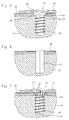
- FIG 1 is schematically the attachment of a furniture fitting 10 on the Surface of a furniture wall 12 with a designated in its entirety by 14 first embodiment of a fastener according to the invention shown in section.
- That basically in furniture today in large Euro screws used corresponding fastener 14 has a frustoconical screw head in the case shown 16, which in the mounting position shown in the drawing So in a complementary complemented in their insertion frusto-conical Passage opening 18 is arranged countersunk in the furniture fitting.
- At the Screw head 16 is provided with the thread typical for Euro screws Screw shaft 20 via an integral on the underside of the screw head 16 molded support portion 22 attached.
- the support section 20 has in the special case the shape of a short cylinder whose Diameter D is substantially equal to the diameter of the lower tapered Base portion of the screw head 16 is. From the opposite Face of the support portion 22 occurs centrally integrally formed Screw shaft 20 before, whose core diameter d is much lower than that Diameter D of the support portion 20 is. The over the tips of the threads the screw shaft 20 measured diameter d 'corresponds approximately or is only slightly smaller than the diameter D of the support portion 22nd
- Extension of the support portion 22 is selected so that the support portion in the manner shown in Fig. 1 recognizable in the intended Mounting position of the furniture fitting 14 on the furniture wall 12 by whose surface extends into the material of the furniture wall, and then in one in the mouth region of - in Fig. 2 separately shown-attachment hole 24 extended bore portion 26 in the furniture wall 12th intervenes.
- the diameter of the enlarged portion 26 is equal to the Diameter D of the support portion 22, so that the support portion 22 in the intended mounting position so complementary in Bore portion 26 is held and supported over a large area.
- Step drill used, which allows the hole shown to produce in one work step.
- FIGs 5 and 7 are compared to the fastener 14 according to Fig. 1 modified fasteners 14 "and 14" ', which a Attachment of furniture fittings 10 on furniture walls 12 allow without that the associated mounting hole 24 in the mouth region in the Diameter enlarged mounting portion 26 must have.
- the fasteners 14 "and 14" may be in simple, over their entire length of a same diameter holes used so that the use of special step drills is eliminated.
- mounting holes then also in today's pieces of furniture often already existing simple holes, as for example are used to accommodate shelf supports, etc., so that a separate step to create the mounting hole completely eliminated.
- the fastener 14 "shown in Fig. 5 is the between the Screw head 16 and the screw shaft 20 provided support portion 22 also enlarged cylindrically, wherein the cylindrical peripheral surface the support portion 22 has a diameter D of the fastener 14 corresponding diameter.
- the end surface area of the support portion 22 is additionally one Number of circumferentially offset cutting teeth 30 incorporated, which when mounting the furniture fitting 10 before reaching cut the final fixing position into the material of the furniture wall and thus the extended bore portion 26 of FIG. 2 cut yourself during the fastening process.
- the fastening element 14 "'according to FIG. 7 differs from the fastening element 14 "in that the mounting area 22 is not cylindrical, but has a frusto-conical outer boundary wall, in which in turn, a number of circumferentially offset in the illustrated case arranged cutting teeth 32 are incorporated, which at a Rotation of the fastener 14 "'in the screwing the associated complementary tapered seat in the mounting hole 24 of FIG. 6 generate itself by the material during rotation of the fastener in the mouth region of the bore 24 by material removal accordingly the outer frusto-conical boundary of the frustoconical here Holding portion 22 itself is generated.
- the holding portion 22 in this case also fulfills the additional function of a countersink drill.
Landscapes
- Engineering & Computer Science (AREA)
- General Engineering & Computer Science (AREA)
- Mechanical Engineering (AREA)
- Connection Of Plates (AREA)
- Furniture Connections (AREA)
Abstract
Description
- Fig. 1
- eine Schnittansicht durch den Befestigungsbereich mittels eines ersten Ausführungsbeispiels eines erfindungsgemäßen Befestigungselements auf der Oberfläche einer Möbelwand befestigten Möbelbeschlags;
- Fig. 2
- eine in der Schnittführung der Fig. 1 entsprechende Schnittansicht durch die Möbelwand ohne Möbelbeschlag und Befestigungselement, so dass die Form der für das Befestigungselement gemäß Fig. 1 erforderliche Vorbohrung in der Möbelwand erkennbar ist;
- Fig. 3
- eine in der Schnittführung der Fig. 1 entsprechende Schnittansicht durch eine mit einem zweiten Ausführungsbeispiel eines erfindungsgemäßen Befestigungselements auf einer Möbelwand befestigten Möbelbeschlags;
- Fig. 4
- eine der Fig. 3 entsprechende Schnittansicht durch die dort vorgesehene Möbelwand vor dem Befestigen des Möbelbeschlagteils mittels des dort verwendeten Befestigungselements;
- Fig. 5
- eine den Fig. 1 und 3 entsprechende Schnittansicht, in welcher die Befestigung des Möbelbeschlags durch ein drittes Ausführungsbeispiel eines erfindungsgemäßen Befestigungselements auf der Möbelwand veranschaulicht ist;
- Fig. 6
- eine der Fig. 5 entsprechende Schnittansicht durch die Möbelwand vor der Befestigung des Möbelbeschlags mit dem in Fig. 5 verwendeten erfindungsgemäßen Befestigungselement; und
- Fig. 7
- eine der Fig. 5 entsprechende Schnittansicht, bei welcher der Möbelbeschlag unter Verwendung eines gegenüber dem dritten Ausführungsbeispiel abgewandelten vierten Ausführungsbeispiels eines erfindungsgemäßen Befestigungselements auf der Möbelwand gehalten ist.
Claims (9)
- Befestigungselement (14; 14'; 14";) nach Art einer Befestigungsschraube für die Befestigung von Möbelbeschlägen (10) auf der Oberfläche von Möbelwandungen mit einem durch eine Bohrung (18) im Möbelbeschlag (10) hindurch in eine Befestigungsbohrung in der Möbelwandung einführbaren Gewindeschaft (20), an dessen äußerem freien Ende ein Schraubenkopf (16) vorgesehen ist,
dadurch gekennzeichnet, dass im Übergangsbereich des Schafts (20) zum Schraubenkopf (16) ein Halterungsabschnitt (22) vorgesehen ist, dessen Durchmesser (D) kleiner als der Außendurchmesser des Schraubenkopfs (16) und zumindest abschnittsweise größer als der Durchmesser (d) des Schafts (20) ist,
dass die in Richtung der Längsmittelachse des Schafts (20) gemessene Länge des Halteerungsabschnitts (22)so gewählt ist, dass dieser sich in der bestimmungsgemäßen Befestigungsstellung des Möbelbeschlags (10) auf der zugeordneten Möbelwand (12) durch deren Oberfläche hindurch ins Material der Möbelwand erstreckt, und
dass der Halterungsabschnitt (22) eine im Wesentlichen zylindrische Außenfläche aufweist. - Befestigungselement nach Anspruch 1, dadurch gekennzeichnet, dass der Halterungsabschnitt (22) an seiner in Einschraubrichtung vorderen, zum Schraubenschaft (20) weisenden Stirnfläche mit wenigstens einem eine im Wesentlichen radial verlaufende Schneidkante aufweisenden, bei der Drehung der Schraube in Einschraubrichtung spanend ins Material der Möbelwandung eindringenden Schneidzahn bzw. Schneidzähnen (30) versehen ist.
- Befestigungselement nach Anspruch 2, dadurch gekennzeichnet, dass an der Stirnfläche des Halterungsabschnitts (22) zwei oder mehr in gleichmäßigen Winkelabständen in Umfangsrichtung versetzte Schneidzähne (30) vorgesehen sind.
- Befestigungselement nach einem der Ansprüche 1 bis 3, dadurch gekennzeichnet, dass der Halterungsabschnitt (22) im Bereich seiner vorderen Stirnfläche wenigstens einen radial außen bündig in die zylindrische Oberfläche übergehenden, in Einschraubrichtung vortretenden messerartigen Schneidzahn (30) aufweist.
- Befestigungselement nach Anspruch 4, dadurch gekennzeichnet, dass wenigstens zwei vorzugsweise drei oder mehr in Umfangsrichtung in gleichmäßigen Winkelabständen versetzt angeordnete messerartige Schneidzähne (30) vorgesehen sind.
- Befestigungselement (14"') nach Art einer Befestigungsschraube für die Befestigung von Möbelbeschlägen (10) auf der Oberfläche von Möbelwandungen mit einem durch eine Bohrung (18) im Möbelbeschlag (10) hindurch in eine Befestigungsbohrung in der Möbelwandung einführbaren Gewindeschaft (20), an dessen äußerem freien Ende ein Schraubenkopf (16) vorgesehen ist,
dadurch gekennzeichnet, dass im Übergangsbereich des Schafts (20) zum Schraubenkopf (16) ein im Wesentlichen kegelstumpfförmiger Halterungsabschnitt (22) vorgesehen ist, dessen kegelstumpfförmige Aussenfläche unmittelbar im Anschluss an den Schraubenkopf einen Durchmesser (D) aufweist, der kleiner als der Außendurchmesser des Schraubenkopfs (16) im Übergangsbereich zum Schaft und zumindest abschnittsweise größer als der Durchmesser (d) des Schafts (20) ist, und
dass in die im Wesentlichen kegelstumpfförmige Außenfläche des Halterungsabschnitts (22) wenigstens ein nach Art der Schneidmesser von Fräswerkzeugen mit jeweils einer Schneidkante versehenes Schneidmesser (32) eingearbeitet ist. - Bearbeitungswerkzeug nach Anspruch 6, dadurch gekennzeichnet, dass wenigstens zwei vorzugsweise drei oder mehr in gleichmäßigen Winkelabständen auf der Außenfläche des Halterungsabschnitts (22) versetzt angeordnete Schneidmesser (32) vorgesehen sind.
- Befestigungselement nach Anspruch 6 oder 7, dadurch gekennzeichnet, dass das Schneidmesser bzw. die Schneidmesser sich im Wesentlichen über die gesamte Länge der kegelstumpfförmigen Außenfläche des Halterungsabschnitts (22) erstrecken.
- Befestigungselement nach Anspruch 6 oder 7, dadurch gekennzeichnet, dass der Schneidzahn bzw. die Schneidzähne (32) sich nur über einen Teilabschnitt der kegelstumpfförmigen Außenfläche des Halterungsabschnitts (22) erstreckt bzw. erstrecken, wobei im unmittelbaren Übergangsbereich zum Schraubenkopf (16) ein ununterbrochener umlaufender kegelstumpfförmiger Übergangsabschnitt ohne Schneidzahn bzw. Schneidzähne verbleibt.
Applications Claiming Priority (2)
| Application Number | Priority Date | Filing Date | Title |
|---|---|---|---|
| DE202004005460U | 2004-04-07 | ||
| DE200420005460 DE202004005460U1 (de) | 2004-04-07 | 2004-04-07 | Befestigungselement für Möbelbeschläge |
Publications (3)
| Publication Number | Publication Date |
|---|---|
| EP1584825A2 true EP1584825A2 (de) | 2005-10-12 |
| EP1584825A3 EP1584825A3 (de) | 2009-06-24 |
| EP1584825B1 EP1584825B1 (de) | 2017-07-05 |
Family
ID=34895657
Family Applications (1)
| Application Number | Title | Priority Date | Filing Date |
|---|---|---|---|
| EP05007375.8A Expired - Lifetime EP1584825B1 (de) | 2004-04-07 | 2005-04-05 | Befestigungselement für Möbelbeschläge |
Country Status (3)
| Country | Link |
|---|---|
| EP (1) | EP1584825B1 (de) |
| DE (1) | DE202004005460U1 (de) |
| ES (1) | ES2637751T3 (de) |
Families Citing this family (1)
| Publication number | Priority date | Publication date | Assignee | Title |
|---|---|---|---|---|
| WO2007031097A1 (de) * | 2005-09-09 | 2007-03-22 | Hueser Eckhart | System und verfahren zum bilden von unterteilungen an ablageflächen |
Family Cites Families (9)
| Publication number | Priority date | Publication date | Assignee | Title |
|---|---|---|---|---|
| US3477337A (en) * | 1968-02-27 | 1969-11-11 | John A Racki | Universal internal thread fastener assembly |
| DE3512991A1 (de) * | 1985-04-11 | 1986-10-16 | Fichtel & Sachs Ag, 8720 Schweinfurt | In einem sackloch sich selbst verankernder senkbolzen |
| US4827756A (en) * | 1987-01-09 | 1989-05-09 | Textron Inc. | Fastener fabrication method |
| DE3706144C2 (de) * | 1987-02-26 | 1999-02-04 | Adolf Wuerth Gmbh & Co Kg | Senkschraube |
| DE4228727A1 (de) * | 1992-08-28 | 1994-03-03 | Adolf Wuerth Gmbh & Co Kg | Schraube, insbesondere für Hartholz |
| DE19505311C2 (de) * | 1995-02-17 | 2002-04-11 | Lautenschlaeger Mepla Werke | Befestigungsanordnung von Beschlägen, insbesondere Möbelbeschlägen an Möbelstücken |
| DE19506081A1 (de) * | 1995-02-22 | 1996-08-29 | Letsch Klaus Peter | Befestigungselement |
| DE29900494U1 (de) * | 1999-01-14 | 2000-08-31 | Lautenschlaeger Mepla Werke | Befestigungszapfen für die Montage von Werkstücken, insbesondere von Möbelbeschlägen |
| PL349071A1 (en) * | 1999-02-01 | 2002-07-01 | Atoma Int Corp | Staking and mounting pin for a vehicle door latch |
-
2004
- 2004-04-07 DE DE200420005460 patent/DE202004005460U1/de not_active Expired - Lifetime
-
2005
- 2005-04-05 EP EP05007375.8A patent/EP1584825B1/de not_active Expired - Lifetime
- 2005-04-05 ES ES05007375.8T patent/ES2637751T3/es not_active Expired - Lifetime
Also Published As
| Publication number | Publication date |
|---|---|
| EP1584825B1 (de) | 2017-07-05 |
| DE202004005460U1 (de) | 2005-09-01 |
| EP1584825A3 (de) | 2009-06-24 |
| ES2637751T3 (es) | 2017-10-16 |
Similar Documents
| Publication | Publication Date | Title |
|---|---|---|
| EP2084409A1 (de) | Anordnung mit einer hohlplatte und einem verbindungsbeschlag | |
| EP0292742B1 (de) | Distanzschraube | |
| DE19831338C2 (de) | Knochenschraube | |
| DE102015219778A1 (de) | Möbelteilverbindungsanordnung | |
| EP3726072B1 (de) | Schraube für holzwerkstoffe | |
| EP2379260A1 (de) | Werkzeug für die spanende bearbeitung, insbesondere langdrehwerkzeug | |
| EP1214914B1 (de) | Verriegelungsschraube für Implantate | |
| DE29507834U1 (de) | Reling-Befestigungsanordnung an Schubladen | |
| DE102013105443A1 (de) | Befestigungselement | |
| DE102016101519A1 (de) | Schraube, Befestigungsanordnung, Verwendung einer Befestigungsanordnung und Verfahren zum Herstellen einer Schraube | |
| EP2577074B1 (de) | Selbstbohrende schraube | |
| DE202009012420U1 (de) | Montagesystem für Isolierstoffplatten | |
| EP1584825B1 (de) | Befestigungselement für Möbelbeschläge | |
| WO2025051555A1 (de) | Trockenbaudübel und verfahren zur montage des trockenbaudübels | |
| EP0527999B1 (de) | Schraube zum eindrehen in sacklöcher geringer tiefe | |
| EP4459138A1 (de) | Dämmstoffanker | |
| WO2019238439A1 (de) | Schraube | |
| DE102017217743A1 (de) | Schraube | |
| DE102014000894A1 (de) | Verfahren zum Herstellen einer Befestigungsanordnung, Befestigungsanordnung und dafür vorgesehene Schraube | |
| DE10035569B4 (de) | Beschlagsteil für ein Fenster, eine Tür oder dergleichen | |
| EP0867252B1 (de) | Werkzeug zur Herstellung eines Gewindes in einem Werkstück, vorzugsweise Gewindebohrer | |
| EP2085533A2 (de) | Verbindungsvorrichtung zur Verbindung von Stufe und Wange einer Treppe | |
| DE102010013529A1 (de) | Griffanordnung | |
| DE102008011334A1 (de) | Griffbefestigung | |
| DE102023111531A1 (de) | Dämmstoffanker |
Legal Events
| Date | Code | Title | Description |
|---|---|---|---|
| PUAI | Public reference made under article 153(3) epc to a published international application that has entered the european phase |
Free format text: ORIGINAL CODE: 0009012 |
|
| AK | Designated contracting states |
Kind code of ref document: A2 Designated state(s): AT BE BG CH CY CZ DE DK EE ES FI FR GB GR HU IE IS IT LI LT LU MC NL PL PT RO SE SI SK TR |
|
| AX | Request for extension of the european patent |
Extension state: AL BA HR LV MK YU |
|
| PUAL | Search report despatched |
Free format text: ORIGINAL CODE: 0009013 |
|
| AK | Designated contracting states |
Kind code of ref document: A3 Designated state(s): AT BE BG CH CY CZ DE DK EE ES FI FR GB GR HU IE IS IT LI LT LU MC NL PL PT RO SE SI SK TR |
|
| AX | Request for extension of the european patent |
Extension state: AL BA HR LV MK YU |
|
| 17P | Request for examination filed |
Effective date: 20090623 |
|
| 17Q | First examination report despatched |
Effective date: 20090806 |
|
| AKX | Designation fees paid |
Designated state(s): AT BE BG CH CY CZ DE DK EE ES FI FR GB GR HU IE IS IT LI LT LU MC NL PL PT RO SE SI SK TR |
|
| GRAP | Despatch of communication of intention to grant a patent |
Free format text: ORIGINAL CODE: EPIDOSNIGR1 |
|
| INTG | Intention to grant announced |
Effective date: 20170220 |
|
| GRAS | Grant fee paid |
Free format text: ORIGINAL CODE: EPIDOSNIGR3 |
|
| GRAA | (expected) grant |
Free format text: ORIGINAL CODE: 0009210 |
|
| AK | Designated contracting states |
Kind code of ref document: B1 Designated state(s): AT BE BG CH CY CZ DE DK EE ES FI FR GB GR HU IE IS IT LI LT LU MC NL PL PT RO SE SI SK TR |
|
| REG | Reference to a national code |
Ref country code: GB Ref legal event code: FG4D Free format text: NOT ENGLISH |
|
| REG | Reference to a national code |
Ref country code: CH Ref legal event code: EP |
|
| REG | Reference to a national code |
Ref country code: AT Ref legal event code: REF Ref document number: 906813 Country of ref document: AT Kind code of ref document: T Effective date: 20170715 |
|
| REG | Reference to a national code |
Ref country code: IE Ref legal event code: FG4D Free format text: LANGUAGE OF EP DOCUMENT: GERMAN |
|
| REG | Reference to a national code |
Ref country code: DE Ref legal event code: R096 Ref document number: 502005015641 Country of ref document: DE |
|
| REG | Reference to a national code |
Ref country code: ES Ref legal event code: FG2A Ref document number: 2637751 Country of ref document: ES Kind code of ref document: T3 Effective date: 20171016 |
|
| REG | Reference to a national code |
Ref country code: NL Ref legal event code: MP Effective date: 20170705 |
|
| REG | Reference to a national code |
Ref country code: LT Ref legal event code: MG4D |
|
| PG25 | Lapsed in a contracting state [announced via postgrant information from national office to epo] |
Ref country code: FI Free format text: LAPSE BECAUSE OF FAILURE TO SUBMIT A TRANSLATION OF THE DESCRIPTION OR TO PAY THE FEE WITHIN THE PRESCRIBED TIME-LIMIT Effective date: 20170705 Ref country code: LT Free format text: LAPSE BECAUSE OF FAILURE TO SUBMIT A TRANSLATION OF THE DESCRIPTION OR TO PAY THE FEE WITHIN THE PRESCRIBED TIME-LIMIT Effective date: 20170705 Ref country code: SE Free format text: LAPSE BECAUSE OF FAILURE TO SUBMIT A TRANSLATION OF THE DESCRIPTION OR TO PAY THE FEE WITHIN THE PRESCRIBED TIME-LIMIT Effective date: 20170705 Ref country code: NL Free format text: LAPSE BECAUSE OF FAILURE TO SUBMIT A TRANSLATION OF THE DESCRIPTION OR TO PAY THE FEE WITHIN THE PRESCRIBED TIME-LIMIT Effective date: 20170705 |
|
| PG25 | Lapsed in a contracting state [announced via postgrant information from national office to epo] |
Ref country code: IS Free format text: LAPSE BECAUSE OF FAILURE TO SUBMIT A TRANSLATION OF THE DESCRIPTION OR TO PAY THE FEE WITHIN THE PRESCRIBED TIME-LIMIT Effective date: 20171105 Ref country code: BG Free format text: LAPSE BECAUSE OF FAILURE TO SUBMIT A TRANSLATION OF THE DESCRIPTION OR TO PAY THE FEE WITHIN THE PRESCRIBED TIME-LIMIT Effective date: 20171005 Ref country code: GR Free format text: LAPSE BECAUSE OF FAILURE TO SUBMIT A TRANSLATION OF THE DESCRIPTION OR TO PAY THE FEE WITHIN THE PRESCRIBED TIME-LIMIT Effective date: 20171006 Ref country code: PL Free format text: LAPSE BECAUSE OF FAILURE TO SUBMIT A TRANSLATION OF THE DESCRIPTION OR TO PAY THE FEE WITHIN THE PRESCRIBED TIME-LIMIT Effective date: 20170705 |
|
| REG | Reference to a national code |
Ref country code: DE Ref legal event code: R097 Ref document number: 502005015641 Country of ref document: DE |
|
| PG25 | Lapsed in a contracting state [announced via postgrant information from national office to epo] |
Ref country code: RO Free format text: LAPSE BECAUSE OF FAILURE TO SUBMIT A TRANSLATION OF THE DESCRIPTION OR TO PAY THE FEE WITHIN THE PRESCRIBED TIME-LIMIT Effective date: 20170705 Ref country code: DK Free format text: LAPSE BECAUSE OF FAILURE TO SUBMIT A TRANSLATION OF THE DESCRIPTION OR TO PAY THE FEE WITHIN THE PRESCRIBED TIME-LIMIT Effective date: 20170705 Ref country code: CZ Free format text: LAPSE BECAUSE OF FAILURE TO SUBMIT A TRANSLATION OF THE DESCRIPTION OR TO PAY THE FEE WITHIN THE PRESCRIBED TIME-LIMIT Effective date: 20170705 |
|
| PLBE | No opposition filed within time limit |
Free format text: ORIGINAL CODE: 0009261 |
|
| STAA | Information on the status of an ep patent application or granted ep patent |
Free format text: STATUS: NO OPPOSITION FILED WITHIN TIME LIMIT |
|
| PG25 | Lapsed in a contracting state [announced via postgrant information from national office to epo] |
Ref country code: EE Free format text: LAPSE BECAUSE OF FAILURE TO SUBMIT A TRANSLATION OF THE DESCRIPTION OR TO PAY THE FEE WITHIN THE PRESCRIBED TIME-LIMIT Effective date: 20170705 Ref country code: SK Free format text: LAPSE BECAUSE OF FAILURE TO SUBMIT A TRANSLATION OF THE DESCRIPTION OR TO PAY THE FEE WITHIN THE PRESCRIBED TIME-LIMIT Effective date: 20170705 |
|
| 26N | No opposition filed |
Effective date: 20180406 |
|
| PGFP | Annual fee paid to national office [announced via postgrant information from national office to epo] |
Ref country code: ES Payment date: 20180525 Year of fee payment: 14 |
|
| PG25 | Lapsed in a contracting state [announced via postgrant information from national office to epo] |
Ref country code: SI Free format text: LAPSE BECAUSE OF FAILURE TO SUBMIT A TRANSLATION OF THE DESCRIPTION OR TO PAY THE FEE WITHIN THE PRESCRIBED TIME-LIMIT Effective date: 20170705 |
|
| PGFP | Annual fee paid to national office [announced via postgrant information from national office to epo] |
Ref country code: IT Payment date: 20180420 Year of fee payment: 14 |
|
| PG25 | Lapsed in a contracting state [announced via postgrant information from national office to epo] |
Ref country code: MC Free format text: LAPSE BECAUSE OF FAILURE TO SUBMIT A TRANSLATION OF THE DESCRIPTION OR TO PAY THE FEE WITHIN THE PRESCRIBED TIME-LIMIT Effective date: 20170705 |
|
| REG | Reference to a national code |
Ref country code: CH Ref legal event code: PL |
|
| REG | Reference to a national code |
Ref country code: BE Ref legal event code: MM Effective date: 20180430 |
|
| GBPC | Gb: european patent ceased through non-payment of renewal fee |
Effective date: 20180405 |
|
| REG | Reference to a national code |
Ref country code: IE Ref legal event code: MM4A |
|
| PG25 | Lapsed in a contracting state [announced via postgrant information from national office to epo] |
Ref country code: LU Free format text: LAPSE BECAUSE OF NON-PAYMENT OF DUE FEES Effective date: 20180405 |
|
| PG25 | Lapsed in a contracting state [announced via postgrant information from national office to epo] |
Ref country code: BE Free format text: LAPSE BECAUSE OF NON-PAYMENT OF DUE FEES Effective date: 20180430 Ref country code: CH Free format text: LAPSE BECAUSE OF NON-PAYMENT OF DUE FEES Effective date: 20180430 Ref country code: GB Free format text: LAPSE BECAUSE OF NON-PAYMENT OF DUE FEES Effective date: 20180405 Ref country code: LI Free format text: LAPSE BECAUSE OF NON-PAYMENT OF DUE FEES Effective date: 20180430 |
|
| PG25 | Lapsed in a contracting state [announced via postgrant information from national office to epo] |
Ref country code: IE Free format text: LAPSE BECAUSE OF NON-PAYMENT OF DUE FEES Effective date: 20180405 Ref country code: FR Free format text: LAPSE BECAUSE OF NON-PAYMENT OF DUE FEES Effective date: 20180430 |
|
| PGFP | Annual fee paid to national office [announced via postgrant information from national office to epo] |
Ref country code: DE Payment date: 20190228 Year of fee payment: 15 |
|
| PGFP | Annual fee paid to national office [announced via postgrant information from national office to epo] |
Ref country code: AT Payment date: 20190301 Year of fee payment: 15 |
|
| PG25 | Lapsed in a contracting state [announced via postgrant information from national office to epo] |
Ref country code: TR Free format text: LAPSE BECAUSE OF FAILURE TO SUBMIT A TRANSLATION OF THE DESCRIPTION OR TO PAY THE FEE WITHIN THE PRESCRIBED TIME-LIMIT Effective date: 20170705 |
|
| PG25 | Lapsed in a contracting state [announced via postgrant information from national office to epo] |
Ref country code: IT Free format text: LAPSE BECAUSE OF NON-PAYMENT OF DUE FEES Effective date: 20190405 |
|
| PG25 | Lapsed in a contracting state [announced via postgrant information from national office to epo] |
Ref country code: HU Free format text: LAPSE BECAUSE OF FAILURE TO SUBMIT A TRANSLATION OF THE DESCRIPTION OR TO PAY THE FEE WITHIN THE PRESCRIBED TIME-LIMIT; INVALID AB INITIO Effective date: 20050405 Ref country code: PT Free format text: LAPSE BECAUSE OF FAILURE TO SUBMIT A TRANSLATION OF THE DESCRIPTION OR TO PAY THE FEE WITHIN THE PRESCRIBED TIME-LIMIT Effective date: 20170705 |
|
| PG25 | Lapsed in a contracting state [announced via postgrant information from national office to epo] |
Ref country code: CY Free format text: LAPSE BECAUSE OF FAILURE TO SUBMIT A TRANSLATION OF THE DESCRIPTION OR TO PAY THE FEE WITHIN THE PRESCRIBED TIME-LIMIT Effective date: 20170705 |
|
| REG | Reference to a national code |
Ref country code: ES Ref legal event code: FD2A Effective date: 20200828 |
|
| PG25 | Lapsed in a contracting state [announced via postgrant information from national office to epo] |
Ref country code: ES Free format text: LAPSE BECAUSE OF NON-PAYMENT OF DUE FEES Effective date: 20190406 |
|
| REG | Reference to a national code |
Ref country code: DE Ref legal event code: R119 Ref document number: 502005015641 Country of ref document: DE |
|
| REG | Reference to a national code |
Ref country code: AT Ref legal event code: MM01 Ref document number: 906813 Country of ref document: AT Kind code of ref document: T Effective date: 20200405 |
|
| PG25 | Lapsed in a contracting state [announced via postgrant information from national office to epo] |
Ref country code: DE Free format text: LAPSE BECAUSE OF NON-PAYMENT OF DUE FEES Effective date: 20201103 Ref country code: AT Free format text: LAPSE BECAUSE OF NON-PAYMENT OF DUE FEES Effective date: 20200405 |
|
| P01 | Opt-out of the competence of the unified patent court (upc) registered |
Effective date: 20230519 |