EP1584758A2 - Water tap - Google Patents
Water tap Download PDFInfo
- Publication number
- EP1584758A2 EP1584758A2 EP05007062A EP05007062A EP1584758A2 EP 1584758 A2 EP1584758 A2 EP 1584758A2 EP 05007062 A EP05007062 A EP 05007062A EP 05007062 A EP05007062 A EP 05007062A EP 1584758 A2 EP1584758 A2 EP 1584758A2
- Authority
- EP
- European Patent Office
- Prior art keywords
- water outlet
- projection
- fitting
- connecting element
- outlet pipe
- Prior art date
- Legal status (The legal status is an assumption and is not a legal conclusion. Google has not performed a legal analysis and makes no representation as to the accuracy of the status listed.)
- Withdrawn
Links
Images


Classifications
-
- E—FIXED CONSTRUCTIONS
- E03—WATER SUPPLY; SEWERAGE
- E03C—DOMESTIC PLUMBING INSTALLATIONS FOR FRESH WATER OR WASTE WATER; SINKS
- E03C1/00—Domestic plumbing installations for fresh water or waste water; Sinks
- E03C1/02—Plumbing installations for fresh water
- E03C1/04—Water-basin installations specially adapted to wash-basins or baths
- E03C1/0404—Constructional or functional features of the spout
-
- E—FIXED CONSTRUCTIONS
- E03—WATER SUPPLY; SEWERAGE
- E03C—DOMESTIC PLUMBING INSTALLATIONS FOR FRESH WATER OR WASTE WATER; SINKS
- E03C1/00—Domestic plumbing installations for fresh water or waste water; Sinks
- E03C1/02—Plumbing installations for fresh water
- E03C1/04—Water-basin installations specially adapted to wash-basins or baths
- E03C2001/0417—Water-basin installations specially adapted to wash-basins or baths having space-saving features, e.g. retractable, demountable
-
- Y—GENERAL TAGGING OF NEW TECHNOLOGICAL DEVELOPMENTS; GENERAL TAGGING OF CROSS-SECTIONAL TECHNOLOGIES SPANNING OVER SEVERAL SECTIONS OF THE IPC; TECHNICAL SUBJECTS COVERED BY FORMER USPC CROSS-REFERENCE ART COLLECTIONS [XRACs] AND DIGESTS
- Y10—TECHNICAL SUBJECTS COVERED BY FORMER USPC
- Y10T—TECHNICAL SUBJECTS COVERED BY FORMER US CLASSIFICATION
- Y10T137/00—Fluid handling
- Y10T137/8593—Systems
- Y10T137/8807—Articulated or swinging flow conduit
Definitions
- the present invention relates to a water outlet fitting with a hinged water outlet pipe, the water outlet pipe over a Connecting element is rotatably connected to a fitting body.
- the invention further relates to a single-lever mixer, in particular for installation in Caravans and caravans.
- Water outlet fittings with a hinged water outlet pipe are known and are especially installed in caravans and caravans.
- Caravans and motorhomes often exist the need of using very low fittings in sinks with hinged glass cover.
- the fittings used in this way usually can not reach the height of 40 mm exceed.
- the known previous fittings have the disadvantage that after a certain period of use or even at different Temperatures a relaxation of the outlet pipe connection occurs. This leads to, that the spout drops by itself or when you turn on the Water flow is thrown upwards. So far, the strength of the Spill over the friction of two plastic parts or the use of achieved large-sized O-rings.
- these solutions also occur again and again problems with the strength of the outlet pipe connection.
- a water outlet fitting according to the invention has a hinged Water outlet pipe, wherein the water outlet pipe via a connecting element is rotatably connected to a fitting body and wherein the Connecting element and the fitting body formed latching with each other are, wherein the latch has at least one latching steps.
- a further advantageous embodiment of the invention are at least two Recesses arranged in a circle. It is possible to do a variety of To arrange recesses radially at equal distances from each other. As a result, on the one hand a problem-free movement of the water outlet pipe of a rest position in an operating position or vice versa guaranteed and On the other hand, by a plurality of recesses of the inclination angle of Water outlet pipe can be varied almost arbitrarily.
- the projection or the projections are resiliently arranged. This makes it possible, despite the Latching or toothing of the connecting element with the fitting body the water outlet pipe without too much effort in the appropriate To transfer detent positions.
- One design option is training the projection or the projections of an elastic material. Furthermore it is possible that the projection and the recesses each rounded are formed.
- An inventive single lever mixer in particular for installation in Caravans and caravans have a water outlet fitting according to the Previously described embodiments.
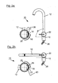
- FIG. 1 shows a schematic illustration of a water outlet fitting 10 according to a first embodiment.
- the water outlet fitting has a hinged water outlet pipe 12, which via a connecting element 14th is rotatably connected to a fitting body 16.
- the connecting element 14 is cylindrical and has a housing 28 with a housing opening 30th on.
- the housing opening 30 is used for releasably introducing the water outlet pipe 12.
- the fitting body 16 is in the connection region to the connecting element 14 also cylindrical and also has water inlets 26 and a Fastening device 42 with an external thread for fastening the Water outlet fitting 10 on.
- On the fitting body 16 also includes a On / off device 22 with a lever 24 at.
- the illustrated Embodiment is a so-called single lever mixer.
- the connecting element 14 and the fitting body 16 formed latching with each other, wherein the latching two latching steps having.
- a projection 18 is in the interior of the fitting body 16 formed, wherein the projection 18 in two in the interior of the Voritatisiatas 14 trained recesses can be introduced and latched.
- the two recesses 20 circular and at an angular distance of 90 ° are arranged.
- the projection 18 in the middle of a spring element consisting of the spring arms 38 and 40 is seated.
- a frame 34 is also formed, which has a Bushing 32 for receiving a connecting pin 36 of the fitting body 16th formed.
- the frame 34 is via webs 44 with the inner circumference of the Housing 28 connected.
- the water outlet pipe 12, the connecting element 14, the fitting body 16 and the on / off switch 22 consist usually made of plastic.
- FIGs 2a and 2b show a schematic representation of two different locking positions of the water outlet fitting 10 according to the first Embodiment.
- Figure 2a is an operating position of the water outlet fitting 10 is shown. It can be seen that the water outlet pipe 12 is approximately perpendicular to an imaginary mounting plane lies. It can be seen that the spring-mounted Projection in a first recess 20 is locked.
- Figure 2b a resting or transport position of the water outlet fitting 10 shown. You realize that the water outlet pipe 12 now approximately parallel to an imaginary Mounting level is. In addition, it has become inside the opening 30 of the housing 28 turned the connecting element 14.
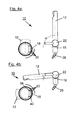
- FIG. 3 shows a schematic representation of a water outlet fitting 10 according to FIG a second embodiment.
- the water outlet fitting 10 in turn a water outlet pipe 12, which in the now described Embodiment is currently formed.
- the water outlet pipe 12 is in turn attached in the connecting element 14.
- the connecting element 14 and the Faucet body 16 are also latched together, the Locking has a plurality of latching steps.
- a projection 18 is formed, wherein the projection 18 in a plurality from formed in the interior of the connecting element 14 recesses 20th can be inserted and latched.
- the recesses 20 are again circular are arranged.
- the projection 18 and the recesses 20 rounded.
- the projection 18 lies on the spring element consisting of the spring arms 38 and 40 on.
- FIG. 4 a and 4b show a schematic representation of two exemplary Locking positions of the water outlet fitting 10 according to the second Embodiment.
- FIG. 4 a shows a position of the water outlet pipe 12 shown approximately perpendicular to an imaginary mounting plane.
- Figure 4b shows the water outlet pipe 12 in a position in the imaginary mounting plane protrudes.
- the illustrated embodiment for example, a Variety of click stops with 12 ° difference possible.
- the illustrated in Figure 4b Detent position is minus 6 ° relative to the imaginary mounting plane. But it is also possible, other angular distances and thus another Rastchneinannon train.
- Further constructional details of the water outlet fitting 10 According to the second embodiment, we refer to the description of first embodiment.
Abstract
Description
Die vorliegende Erfindung betrifft eine Wasserauslaufarmatur mit einem abklappbaren Wasserauslaufrohr, wobei das Wasserauslaufrohr über ein Verbindungselement mit einem Armaturenkörper drehbar verbunden ist. Die Erfindung betrifft weiterhin einen Einhebelmischer, insbesondere für den Einbau in Wohnwagen und Caravans.The present invention relates to a water outlet fitting with a hinged water outlet pipe, the water outlet pipe over a Connecting element is rotatably connected to a fitting body. The The invention further relates to a single-lever mixer, in particular for installation in Caravans and caravans.
Wasserauslaufarmaturen mit einem abklappbaren Wasserauslaufrohr sind bekannt und werden insbesondere in Wohnwagen und Caravans eingebaut. In Caravans, Wohnwagen und Reisemobilen besteht oft die Notwendigkeit des Einsatzes von sehr niedrigen Armaturen in Spülen mit abklappbarer Glasabdeckung. Insbesondere dürfen die so verwendeten Armaturen üblicherweise die Höhe von 40 mm nicht überschreiten. Die bekannten bisherigen Armaturen haben jedoch den Nachteil, dass nach einer gewissen Gebrauchszeit oder sogar bei unterschiedlichen Temperaturen eine Erschlaffung der Auslaufrohrverbindung auftritt. Dies führt dazu, dass der Auslauf selbstständig absinkt oder beim Einschalten des Wasserdurchflusses nach oben geschleudert wird. Bisher wurde die Festigkeit des Auslaufs über die Reibung zweier Kunststoffteile oder den Einsatz von großdimensionierten O-Ringen erzielt. Jedoch treten auch bei diesen Lösungen immer wieder Probleme mit der Festigkeit der Auslaufrohrverbindung auf.Water outlet fittings with a hinged water outlet pipe are known and are especially installed in caravans and caravans. In caravans, Caravans and motorhomes often exist the need of using very low fittings in sinks with hinged glass cover. Especially The fittings used in this way usually can not reach the height of 40 mm exceed. However, the known previous fittings have the disadvantage that after a certain period of use or even at different Temperatures a relaxation of the outlet pipe connection occurs. This leads to, that the spout drops by itself or when you turn on the Water flow is thrown upwards. So far, the strength of the Spill over the friction of two plastic parts or the use of achieved large-sized O-rings. However, these solutions also occur again and again problems with the strength of the outlet pipe connection.
Es ist daher Aufgabe der vorliegenden Erfindung, eine gattungsgemäße Wasserauslaufarmatur bereitzustellen, die eine erhöhte Festigkeit einer Auslaufrohrverbindung eines abklappbaren Wasserauslaufrohrs gewährleistet. It is therefore an object of the present invention to provide a generic Provide a water outlet fitting, the increased strength of Outlet pipe connection of a hinged water outlet pipe guaranteed.
Gelöst wird diese Aufgabe durch eine Wasserauslaufarmatur mit den Merkmalen des Anspruchs 1.This problem is solved by a water outlet fitting with the features of claim 1.
Vorteilhafte Ausgestaltungen sind in den Unteransprüchen beschrieben.Advantageous embodiments are described in the subclaims.
Eine erfindungsgemäße Wasserauslaufarmatur weist ein abklappbares Wasserauslaufrohr auf, wobei das Wasserauslaufrohr über ein Verbindungselement mit einem Armaturenkörper drehbar verbunden ist und wobei das Verbindungselement und der Armaturenkörper miteinander verrastend ausgebildet sind, wobei die Verrastung mindestens eine Raststufen aufweist. Durch die Möglichkeit der Verrastung des Verbindungselementes und des Armaturenkörpers in mindestens einer Raststufe ist gewährleistet, dass das Wasserauslaufrohr fest in einer Betriebsstellung gehalten werden kann oder fest in einer abgeklappten Ruheposition bzw. Transportposition gehalten wird. Zur Verrastung des Verbindungselementes und des Armaturenkörpers kann dabei gemäß einer erfindungsgemäßen Ausführungsform im Inneren des Armaturenkörpers mindestens ein Vorsprung ausgebildet sein, wobei der Vorsprung in mindestens eine im Inneren des Verbindungselementes ausgebildete Ausnehmung einbringbar und verrastbar ist.A water outlet fitting according to the invention has a hinged Water outlet pipe, wherein the water outlet pipe via a connecting element is rotatably connected to a fitting body and wherein the Connecting element and the fitting body formed latching with each other are, wherein the latch has at least one latching steps. By the Possibility of locking the connecting element and the fitting body in at least one latching step ensures that the water outlet pipe firmly in an operating position can be kept or fixed in a folded Rest position or transport position is held. For locking the Connecting element and the fitting body can thereby according to a inventive embodiment in the interior of the fitting body at least a projection may be formed, wherein the projection in at least one in the interior formed recess of the connecting element can be introduced and latched is.
In einer weiteren erfindungsgemäßen Ausführungsform ist es jedoch auch möglich, dass im Inneren des Verbindungselementes mindestens ein Vorsprung ausgebildet ist, wobei der Vorsprung in mindestens eine im Inneren des Armaturenkörpers ausgebildete Ausnehmung einbringbar und verrastbar ist. Durch die Verrastung des Verbindungselementes und des Armaturenkörpers ist einerseits die Festigkeit der Auslaufrohrverbindung gewährleistet und andererseits können auch zum Beispiel während der Fahrt eines Wohnmobils keine Klappergeräusche durch ein loses Auslaufrohr entstehen.In a further embodiment of the invention, however, it is also possible that formed in the interior of the connecting element at least one projection is, wherein the projection in at least one inside the fitting body trained recess can be introduced and latched. By latching the Connecting element and the fitting body is on the one hand the strength of Outlet pipe connection guaranteed and on the other hand, for example while driving a motorhome no rattling noises by a loose Outlet pipe arise.
In einer weiteren vorteilhaften Ausgestaltung der Erfindung sind mindestens zwei Ausnehmungen kreisförmig angeordnet. Dabei ist es möglich, eine Vielzahl von Ausnehmungen radial in gleichmäßigen Abständen voneinander anzuordnen. Dadurch wird einerseits ein problemloses Verbringen des Wasserauslaufrohrs von einer Ruheposition in eine Betriebsposition oder umgekehrt gewährleistet und andererseits kann durch eine Vielzahl von Ausnehmungen der Neigungswinkel des Wasserauslaufrohrs nahezu beliebig variiert werden.In a further advantageous embodiment of the invention are at least two Recesses arranged in a circle. It is possible to do a variety of To arrange recesses radially at equal distances from each other. As a result, on the one hand a problem-free movement of the water outlet pipe of a rest position in an operating position or vice versa guaranteed and On the other hand, by a plurality of recesses of the inclination angle of Water outlet pipe can be varied almost arbitrarily.
In einer weiteren vorteilhaften Ausgestaltung der Erfindung ist der Vorsprung bzw. sind die Vorsprünge federnd angeordnet. Dadurch ist es möglich, trotz der Verrastung bzw. Verzahnung des Verbindungselementes mit dem Armaturenkörper das Wasserauslaufrohr ohne allzu großen Kraftaufwand in die entsprechenden Verrastpositionen zu überführen. Eine Ausgestaltungsmöglichkeit ist die Ausbildung des Vorsprungs oder der Vorsprünge aus einem elastischen Material. Des Weiteren ist es möglich, dass der Vorsprung und die Ausnehmungen jeweils abgerundet ausgebildet sind.In a further advantageous embodiment of the invention, the projection or the projections are resiliently arranged. This makes it possible, despite the Latching or toothing of the connecting element with the fitting body the water outlet pipe without too much effort in the appropriate To transfer detent positions. One design option is training the projection or the projections of an elastic material. Furthermore it is possible that the projection and the recesses each rounded are formed.
Ein erfindungsgemäßer Einhebelmischer, insbesondere für den Einbau in Wohnwagen und Caravans weist eine Wasserauslaufarmatur gemäß den im Vorhergehenden beschriebenen Ausführungsbeispielen auf.An inventive single lever mixer, in particular for installation in Caravans and caravans have a water outlet fitting according to the Previously described embodiments.
Weitere Einzelheiten, Merkmale und Vorteile der Erfindung sind in den nachfolgend beschriebenen und zeichnerisch dargestellten Ausführungsbeispielen näher erläutert. Es zeigen:
- Figur 1
- eine schematische Darstellung einer erfindungsgemäßen Wasserauslaufarmatur gemäß einem ersten Ausführungsbeispiel;
- Figuren 2a und 2b
- eine schematische Darstellung von zwei unterschiedlichen Raststellungen der Wasserauslaufarmatur gemäß Figur 1;
- Figur 3
- eine schematische Darstellung einer erfindungsgemäßen Wasserauslaufarmatur gemäß einem zweiten Ausführungsbeispiel; und
- Figuren 4a und 4b
- eine schematische Darstellung von zwei unterschiedlichen Raststellungen der Wasserauslaufarmatur gemäß Figur 3.
- FIG. 1
- a schematic representation of a water outlet fitting according to the invention according to a first embodiment;
- FIGS. 2a and 2b
- a schematic representation of two different locking positions of the water outlet fitting of Figure 1;
- FIG. 3
- a schematic representation of a water outlet fitting according to the invention according to a second embodiment; and
- FIGS. 4a and 4b
- a schematic representation of two different locking positions of the water outlet fitting of Figure 3.
Figur 1 zeigt in einer schematischen Darstellung eine Wasserauslaufarmatur 10
gemäß einem ersten Ausführungsbeispiel. Die Wasserauslaufarmatur weist ein
abklappbares Wasserauslaufrohr 12 auf, welches über ein Verbindungselement 14
mit einem Armaturenkörper 16 drehbar verbunden ist. Das Verbindungselement 14
ist zylindrisch ausgebildet und weist ein Gehäuse 28 mit einer Gehäuseöffnung 30
auf. Die Gehäuseöffnung 30 dient zum lösbaren Einbringen des Wasserauslaufrohrs
12. Der Armaturenkörper 16 ist im Verbindungsbereich zu dem Verbindungselement
14 ebenfalls zylindrisch ausgebildet und weist zudem Wasserzuläufe 26 sowie eine
Befestigungsvorrichtung 42 mit einem Außengewinde zur Befestigung der
Wasserauslaufarmatur 10 auf. An den Armaturenkörper 16 schließt sich zudem eine
Ein-/Ausschaltvorrichtung 22 mit einem Hebel 24 an. In dem dargestellten
Ausführungsbeispiel handelt es sich um einen sogenannten Einhebelmischer.FIG. 1 shows a schematic illustration of a water outlet fitting 10
according to a first embodiment. The water outlet fitting has a
hinged
Man erkennt, dass das Verbindungselement 14 und der Armaturenkörper 16
miteinander verrastend ausgebildet sind, wobei die Verrastung zwei Raststufen
aufweist. Dabei ist im Inneren des Armaturenkörpers 16 ein Vorsprung 18
ausgebildet, wobei der Vorsprung 18 in zwei im Inneren des Vorbindungselementes
14 ausgebildete Ausnehmungen einbringbar und verrastbar ist. Insbesondere wird
die Art der Verrastung aus der Detailzeichnung X deutlich. Man erkennt, dass die
beiden Ausnehmungen 20 kreisförmig und in einem Winkelabstand von 90°
angeordnet sind. Des Weiteren erkennt man, dass der Vorsprung 18 mittig auf
einem Federelement bestehend aus den Federarmen 38 und 40 aufsitzt. Innerhalb
des Verbindungselementes 14 ist zudem ein Rahmen 34 ausgebildet, der eine
Buchse 32 zur Aufnahme eines Verbindungszapfens 36 des Armaturenkörpers 16
ausbildet. Der Rahmen 34 ist dabei über Stege 44 mit dem Innenumfang des
Gehäuses 28 verbunden. Das Wasserauslaufrohr 12, das Verbindungselement 14,
der Armaturenkörper 16 sowie die Ein-/Ausschaltvorrichtung 22 bestehen
üblicherweise aus Kunststoff.It can be seen that the connecting
Die Figuren 2a und 2b zeigen eine schematische Darstellung von zwei
unterschiedlichen Raststellungen der Wasserauslaufarmatur 10 gemäß dem ersten
Ausführungsbeispiel. In Figur 2a ist eine Betriebsposition der Wasserauslaufarmatur
10 dargestellt. Man erkennt, dass das Wasserauslaufrohr 12 ungefähr senkrecht zu
einer gedachten Montageebene liegt. Man erkennt, dass der federnd gelagerte
Vorsprung in einer ersten Ausnehmung 20 verrastet ist. In Figur 2b ist eine Ruhe-
bzw. Transportposition der Wasserauslaufarmatur 10 dargestellt. Man erkennt, dass
das Wasserauslaufrohr 12 nunmehr ungefähr parallel zu einer gedachten
Montageebene liegt. Zudem wurde es innerhalb der Öffnung 30 des Gehäuses 28
des Verbindungselementes 14 gedreht.Figures 2a and 2b show a schematic representation of two
different locking positions of the water outlet fitting 10 according to the first
Embodiment. In Figure 2a is an operating position of the
Figur 3 zeigt eine schematische Darstellung einer Wasserauslaufarmatur 10 gemäß
einem zweiten Ausführungsbeispiel. Die Wasserauslaufarmatur 10 weist wiederum
ein Wasserauslaufrohr 12 auf, das in dem nunmehr beschriebenen
Ausführungsbeispiel gerade ausgebildet ist. Das Wasserauslaufrohr 12 ist wiederum
in dem Verbindungselement 14 befestigt. Das Verbindungselement 14 und der
Armaturenkörper 16 sind ebenfalls miteinander verrastend ausgebildet, wobei die
Verrastung eine Vielzahl von Raststufen aufweist. Im Inneren des Armaturenkörpers
16 ist daher ein Vorsprung 18 ausgebildet, wobei der Vorsprung 18 in eine Vielzahl
von im Inneren des Verbindungselementes 14 ausgebildeten Ausnehmungen 20
einbringbar und verrastbar ist. Dies wird insbesondere aus der Detailzeichnung X
deutlich. Man erkennt, dass die Ausnehmungen 20 wiederum kreisförmig
angeordnet sind. Zudem ist der Vorsprung 18 und die Ausnehmungen 20
abgerundet ausgebildet. Der Vorsprung 18 liegt dabei auf dem Federelement
bestehend aus den Federarmen 38 und 40 auf.FIG. 3 shows a schematic representation of a water outlet fitting 10 according to FIG
a second embodiment. The water outlet fitting 10 in turn
a
Die Figuren 4a und 4b zeigen in einer schematischen Darstellung zwei beispielhafte
Raststellungen der Wasserauslaufarmatur 10 gemäß dem zweiten
Ausführungsbeispiel. In Figur 4a ist eine Stellung des Wasserauslaufrohrs 12
ungefähr senkrecht zu einer gedachten Montageebene dargestellt. Figur 4b zeigt
das Wasserauslaufrohr 12 in einer Stellung, die in die gedachte Montageebene
hineinragt. Mit dem dargestellten Ausführungsbeispiel sind zum Beispiel eine
Vielzahl von Raststufen mit 12° Unterschied möglich. Die in Figur 4b dargestellte
Raststellung beträgt minus 6° bezogen auf die gedachte Montageebene. Es ist aber
auch möglich, andere Winkelabstände und damit eine andere Raststufeneinteilung
auszubilden. Bezüglich weiterer konstruktiver Details der Wasserauslaufarmatur 10
gemäß dem zweiten Ausführungsbeispiel verweisen wir auf die Beschreibung des
ersten Ausführungsbeispiels.Figures 4a and 4b show a schematic representation of two exemplary
Locking positions of the water outlet fitting 10 according to the second
Embodiment. FIG. 4 a shows a position of the
Claims (9)
dadurch gekennzeichnet, dass das Verbindungselement (14) und der Armaturenkörper (16) miteinander verrastend ausgebildet sind, wobei die Verrastung mindestens eine Raststufe aufweist.Water outlet fitting with a hinged water outlet pipe (12), wherein the water outlet pipe (12) via a connecting element (14) is rotatably connected to a fitting body (16),
characterized in that the connecting element (14) and the fitting body (16) are formed latching with each other, wherein the latch has at least one latching step.
dadurch gekennzeichnet, dass im Inneren des Armaturenkörpers (16) mindestens ein Vorsprung (18) ausgebildet ist, wobei der Vorsprung (18) in mindestens eine im Inneren des Verbindungselementes (14) ausgebildete Ausnehmung (20) einbringbar und verrastbar ist.Water outlet fitting according to claim 1,
characterized in that in the interior of the fitting body (16) at least one projection (18) is formed, wherein the projection (18) in at least one in the interior of the connecting element (14) formed recess (20) can be introduced and latched.
dadurch gekennzeichnet, dass im Inneren des Verbindungselementes (14) mindestens ein Vorsprung ausgebildet ist, wobei der Vorsprung in mindestens eine im Inneren des Armaturenkörpers (16) ausgebildete Ausnehmung einbringbar und verrastbar ist.Water outlet fitting according to claim 1,
characterized in that in the interior of the connecting element (14) at least one projection is formed, wherein the projection in at least one in the interior of the fitting body (16) formed recess can be introduced and latched.
dadurch gekennzeichnet, dass mindestens zwei Ausnehmungen (20) kreisförmig angeordnet sind. Water outlet fitting according to one of the preceding claims,
characterized in that at least two recesses (20) are arranged in a circle.
dadurch gekennzeichnet, dass eine Vielzahl von Ausnehmungen (20) radial in gleichmäßigen Abständen voneinander angeordnet sind.Water outlet fitting according to claim 4,
characterized in that a plurality of recesses (20) are arranged radially at equal distances from each other.
dadurch gekennzeichnet, dass der Vorsprung (18) oder die Vorsprünge (18) federnd angeordnet sind.Water outlet fitting according to one of the preceding claims,
characterized in that the projection (18) or the projections (18) are resiliently arranged.
dadurch gekennzeichnet, dass der Vorsprung (18) oder die Vorsprünge (18) aus einem elastischen Material bestehen.Water outlet fitting according to one of claims 1 to 5,
characterized in that the projection (18) or the projections (18) consist of an elastic material.
dadurch gekennzeichnet, dass der Vorsprung (18) und die Ausnehmungen (20) abgerundet ausgebildet sind.Water outlet fitting according to one of the preceding claims,
characterized in that the projection (18) and the recesses (20) are rounded.
Applications Claiming Priority (2)
| Application Number | Priority Date | Filing Date | Title |
|---|---|---|---|
| DE202004005561U | 2004-04-07 | ||
| DE200420005561 DE202004005561U1 (en) | 2004-04-07 | 2004-04-07 | Water outlet fitting |
Publications (2)
| Publication Number | Publication Date |
|---|---|
| EP1584758A2 true EP1584758A2 (en) | 2005-10-12 |
| EP1584758A3 EP1584758A3 (en) | 2006-05-10 |
Family
ID=32668331
Family Applications (1)
| Application Number | Title | Priority Date | Filing Date |
|---|---|---|---|
| EP20050007062 Withdrawn EP1584758A3 (en) | 2004-04-07 | 2005-03-31 | Water tap |
Country Status (3)
| Country | Link |
|---|---|
| US (1) | US20050241701A1 (en) |
| EP (1) | EP1584758A3 (en) |
| DE (1) | DE202004005561U1 (en) |
Families Citing this family (12)
| Publication number | Priority date | Publication date | Assignee | Title |
|---|---|---|---|---|
| DE102004054986A1 (en) * | 2004-11-13 | 2006-05-24 | Hansa Metallwerke Ag | Sanitary tub filling battery |
| US20060157128A1 (en) * | 2005-01-14 | 2006-07-20 | Frackowiak Steven A | Swing spout with positional locking device |
| US20060157127A1 (en) * | 2005-01-14 | 2006-07-20 | Bors Mark S | Swing spout having a rotational detent |
| WO2015010251A1 (en) * | 2013-07-23 | 2015-01-29 | 弗兰卡(中国)厨房系统有限公司 | Liquid discharge apparatus having adjustable shape |
| ITMI20132072A1 (en) | 2013-12-12 | 2015-06-13 | Gm Rubinetterie S R L | DISTRIBUTION DEVICE WITH BLASTING ROD |
| DE102015114327B3 (en) * | 2015-08-28 | 2017-02-09 | Reich Kg, Regel- Und Sicherheitstechnik | Water fitting, in particular for a caravan, caravan, motor caravan or a boat |
| USD793772S1 (en) | 2016-01-19 | 2017-08-08 | Newage Products, Inc. | Modular kitchen |
| CN106996479A (en) | 2016-01-26 | 2017-08-01 | 科勒公司 | Handleset |
| CN107013698B (en) | 2016-01-26 | 2022-04-12 | 科勒公司 | Valve assembly |
| DE202017105096U1 (en) * | 2017-08-24 | 2018-08-30 | Reich Gmbh Regel- Und Sicherheitstechnik | Water fitting, in particular for a caravan, caravan, Motorcaravan or a boat, arrangement of such a water fitting to a piece of furniture, and trailer and vehicle |
| IT201800011074A1 (en) | 2018-12-13 | 2020-06-13 | Vizio Gmbh | DELIVERY DEVICE |
| IT201900024310A1 (en) | 2019-12-17 | 2021-06-17 | Vizio Gmbh | DELIVERY DEVICE |
Family Cites Families (18)
| Publication number | Priority date | Publication date | Assignee | Title |
|---|---|---|---|---|
| US4589445A (en) * | 1984-01-27 | 1986-05-20 | Sanchez Aguilar Ricardo B | Spout operated valve |
| US4592388A (en) * | 1985-02-11 | 1986-06-03 | Indiana Brass, Inc. | Connector assembly for swivel type faucet spout |
| DE3665757D1 (en) * | 1985-03-26 | 1989-10-26 | Walter Holzer | Process and device to actuate a tap |
| US5267336A (en) * | 1992-05-04 | 1993-11-30 | Srico, Inc. | Electro-optical sensor for detecting electric fields |
| US5278924A (en) * | 1993-02-04 | 1994-01-11 | Hughes Aircraft Company | Periodic domain reversal electro-optic modulator |
| US5416859A (en) * | 1993-04-14 | 1995-05-16 | The United States Of America As Represented By The Secretary Of The Navy | Broadband, low drive voltage, electrooptic, intergrated optical modulator |
| US5644664A (en) * | 1994-06-10 | 1997-07-01 | The United States Of America As Represented By The Secretary Of The Navy | Fiber optic digital transmission system |
| KR100261230B1 (en) * | 1997-07-14 | 2000-07-01 | 윤종용 | Integrated optic intensity |
| US6381379B1 (en) * | 2000-02-10 | 2002-04-30 | Codeon Corporation | Optical modulator having coplanar electrodes for controlling chirp |
| US6356673B1 (en) * | 2000-05-05 | 2002-03-12 | The United States Of America As Represented By The Secretary Of The Navy | Low loss coplanar waveguide horn for low drive LiNbO3 modulators |
| US6304685B1 (en) * | 2000-05-05 | 2001-10-16 | The United States Of America As Represented By The Secretary Of The Navy | Low drive voltage LiNbO3 intensity modulator with reduced electrode loss |
| US6425149B1 (en) * | 2000-07-31 | 2002-07-30 | Te-Hsing Wang | Connection device for connecting an extension tube to a faucet |
| US20030012480A1 (en) * | 2001-06-28 | 2003-01-16 | Valerio Pruneri | Integrated optical waveguide device |
| US6760493B2 (en) * | 2001-06-28 | 2004-07-06 | Avanex Corporation | Coplanar integrated optical waveguide electro-optical modulator |
| US20030031400A1 (en) * | 2001-06-28 | 2003-02-13 | Valerio Pruneri | Integrated optical waveguide device |
| US6653630B2 (en) * | 2001-11-30 | 2003-11-25 | Ramot - University Authority For Applied Research & Industrial Development Ltd. | Tailoring domain engineered structures in ferroelectric materials |
| US7027668B2 (en) * | 2002-05-02 | 2006-04-11 | Covega Corporation | Optical modulators with coplanar-waveguide-to-coplanar-strip electrode transitions |
| DE20307530U1 (en) * | 2003-05-14 | 2003-07-24 | Wang Hsin Fa | Gartensprinkler |
-
2004
- 2004-04-07 DE DE200420005561 patent/DE202004005561U1/en not_active Expired - Lifetime
-
2005
- 2005-03-31 EP EP20050007062 patent/EP1584758A3/en not_active Withdrawn
- 2005-04-06 US US11/100,064 patent/US20050241701A1/en not_active Abandoned
Non-Patent Citations (1)
| Title |
|---|
| None |
Also Published As
| Publication number | Publication date |
|---|---|
| US20050241701A1 (en) | 2005-11-03 |
| DE202004005561U1 (en) | 2004-07-01 |
| EP1584758A3 (en) | 2006-05-10 |
Similar Documents
| Publication | Publication Date | Title |
|---|---|---|
| EP1584758A2 (en) | Water tap | |
| DE102008022096B4 (en) | Verriegelungseinstellklemme | |
| EP1780355B1 (en) | Actuation device for the hood of a motor vehicle | |
| DE102018108830A1 (en) | System of an attachment and a holding element | |
| DE19954857B4 (en) | Fastening device for an additional mat | |
| EP1930530B1 (en) | Fitting or lock | |
| DE102008022410A1 (en) | plumbing fixture | |
| EP2912244A2 (en) | Multiple engagement locking device | |
| EP2064454B1 (en) | Fastening device | |
| DE102010006375A1 (en) | Sanitary fitting for e.g. washstands, has threaded bar guided through opening in fitting plate, passage formed from two blind holes arranged opposite to thread sections, and locking ring provided between pressure plate and nut | |
| DE10028648A1 (en) | Lock for a vehicle tail-gate, has a locking lever pivotally mounted on the base plate and connected with a key lock through a key locking rod and a tail-gate latch via a tail-gate latch locking rod | |
| DE202010006900U1 (en) | Actuation device for a parking brake | |
| EP1527930A2 (en) | Device for locking and/or unlocking a fuel filler door | |
| DE4030765A1 (en) | Water tap for mobile home or yacht - is held to mounting plate by spring-loaded projections which engage edge of fixing hole | |
| DE10243305A1 (en) | Swivel outlet for mixer tap has a clip fitting insert which limits the swivel movement in either direction | |
| DE2408207C2 (en) | A sanitary water outlet fitting that can be inserted into a wall opening, in particular a mixer tap for cold and hot water | |
| EP0985773B1 (en) | Water tap with fixing device | |
| DE10159121A1 (en) | Road shaft cover bolting system houses spring-retractable bolt in system housing to engage bottom hole and firmly joined to underside bar held bolted by angled locking ramps. | |
| EP2913448B1 (en) | Drainage actuation device, method for activation of a drain valve and tool for assembling and the preliminary set-up of the drainage actuation device | |
| WO1998046521A1 (en) | Tap | |
| DE2324364A1 (en) | SINGLE HAND MIXING TAP | |
| EP1607552B1 (en) | Handle device | |
| DE102011121570B4 (en) | Door handle assembly for a vehicle | |
| EP3276107B1 (en) | Window handle fitting | |
| DE20115344U1 (en) | Jack system |
Legal Events
| Date | Code | Title | Description |
|---|---|---|---|
| PUAI | Public reference made under article 153(3) epc to a published international application that has entered the european phase |
Free format text: ORIGINAL CODE: 0009012 |
|
| AK | Designated contracting states |
Kind code of ref document: A2 Designated state(s): AT BE BG CH CY CZ DE DK EE ES FI FR GB GR HU IE IS IT LI LT LU MC NL PL PT RO SE SI SK TR |
|
| AX | Request for extension of the european patent |
Extension state: AL BA HR LV MK YU |
|
| PUAL | Search report despatched |
Free format text: ORIGINAL CODE: 0009013 |
|
| AK | Designated contracting states |
Kind code of ref document: A3 Designated state(s): AT BE BG CH CY CZ DE DK EE ES FI FR GB GR HU IE IS IT LI LT LU MC NL PL PT RO SE SI SK TR |
|
| AX | Request for extension of the european patent |
Extension state: AL BA HR LV MK YU |
|
| AKX | Designation fees paid | ||
| STAA | Information on the status of an ep patent application or granted ep patent |
Free format text: STATUS: THE APPLICATION IS DEEMED TO BE WITHDRAWN |
|
| 18D | Application deemed to be withdrawn |
Effective date: 20061111 |
|
| REG | Reference to a national code |
Ref country code: DE Ref legal event code: 8566 |