EP1584530A1 - Steuerverfahren und -vorrichtung für das Bergabrollen eines Fahrzeugs - Google Patents
Steuerverfahren und -vorrichtung für das Bergabrollen eines Fahrzeugs Download PDFInfo
- Publication number
- EP1584530A1 EP1584530A1 EP04290893A EP04290893A EP1584530A1 EP 1584530 A1 EP1584530 A1 EP 1584530A1 EP 04290893 A EP04290893 A EP 04290893A EP 04290893 A EP04290893 A EP 04290893A EP 1584530 A1 EP1584530 A1 EP 1584530A1
- Authority
- EP
- European Patent Office
- Prior art keywords
- speed
- vehicle
- slope
- braking torque
- instantaneous
- Prior art date
- Legal status (The legal status is an assumption and is not a legal conclusion. Google has not performed a legal analysis and makes no representation as to the accuracy of the status listed.)
- Withdrawn
Links
- 238000000034 method Methods 0.000 title claims abstract description 55
- 230000001133 acceleration Effects 0.000 claims abstract description 41
- 238000005259 measurement Methods 0.000 claims abstract description 12
- 230000006870 function Effects 0.000 claims description 17
- 238000012360 testing method Methods 0.000 claims description 15
- 238000012937 correction Methods 0.000 claims description 12
- 230000008569 process Effects 0.000 claims description 10
- 230000002441 reversible effect Effects 0.000 claims description 6
- 230000000750 progressive effect Effects 0.000 claims description 2
- 230000033228 biological regulation Effects 0.000 abstract description 2
- 238000004364 calculation method Methods 0.000 description 7
- 230000006399 behavior Effects 0.000 description 3
- 238000006073 displacement reaction Methods 0.000 description 3
- 238000004088 simulation Methods 0.000 description 3
- 101100536354 Drosophila melanogaster tant gene Proteins 0.000 description 2
- 230000008901 benefit Effects 0.000 description 2
- 238000004891 communication Methods 0.000 description 2
- 230000000994 depressogenic effect Effects 0.000 description 2
- 238000010586 diagram Methods 0.000 description 2
- 230000008014 freezing Effects 0.000 description 2
- 238000007710 freezing Methods 0.000 description 2
- 230000000977 initiatory effect Effects 0.000 description 2
- 230000033001 locomotion Effects 0.000 description 2
- 230000010355 oscillation Effects 0.000 description 2
- 230000002123 temporal effect Effects 0.000 description 2
- 238000009227 behaviour therapy Methods 0.000 description 1
- 230000008859 change Effects 0.000 description 1
- 239000004020 conductor Substances 0.000 description 1
- 238000007796 conventional method Methods 0.000 description 1
- 230000036461 convulsion Effects 0.000 description 1
- 230000007423 decrease Effects 0.000 description 1
- 230000003247 decreasing effect Effects 0.000 description 1
- 230000000881 depressing effect Effects 0.000 description 1
- 238000009795 derivation Methods 0.000 description 1
- 238000001514 detection method Methods 0.000 description 1
- 230000000694 effects Effects 0.000 description 1
- 235000021183 entrée Nutrition 0.000 description 1
- 238000011156 evaluation Methods 0.000 description 1
- 238000012986 modification Methods 0.000 description 1
- 230000004048 modification Effects 0.000 description 1
- 230000007935 neutral effect Effects 0.000 description 1
- 230000004044 response Effects 0.000 description 1
- 230000007704 transition Effects 0.000 description 1
Images


Classifications
-
- B—PERFORMING OPERATIONS; TRANSPORTING
- B60—VEHICLES IN GENERAL
- B60T—VEHICLE BRAKE CONTROL SYSTEMS OR PARTS THEREOF; BRAKE CONTROL SYSTEMS OR PARTS THEREOF, IN GENERAL; ARRANGEMENT OF BRAKING ELEMENTS ON VEHICLES IN GENERAL; PORTABLE DEVICES FOR PREVENTING UNWANTED MOVEMENT OF VEHICLES; VEHICLE MODIFICATIONS TO FACILITATE COOLING OF BRAKES
- B60T7/00—Brake-action initiating means
- B60T7/12—Brake-action initiating means for automatic initiation; for initiation not subject to will of driver or passenger
-
- B—PERFORMING OPERATIONS; TRANSPORTING
- B60—VEHICLES IN GENERAL
- B60T—VEHICLE BRAKE CONTROL SYSTEMS OR PARTS THEREOF; BRAKE CONTROL SYSTEMS OR PARTS THEREOF, IN GENERAL; ARRANGEMENT OF BRAKING ELEMENTS ON VEHICLES IN GENERAL; PORTABLE DEVICES FOR PREVENTING UNWANTED MOVEMENT OF VEHICLES; VEHICLE MODIFICATIONS TO FACILITATE COOLING OF BRAKES
- B60T8/00—Arrangements for adjusting wheel-braking force to meet varying vehicular or ground-surface conditions, e.g. limiting or varying distribution of braking force
- B60T8/24—Arrangements for adjusting wheel-braking force to meet varying vehicular or ground-surface conditions, e.g. limiting or varying distribution of braking force responsive to vehicle inclination or change of direction, e.g. negotiating bends
- B60T8/245—Longitudinal vehicle inclination
-
- B—PERFORMING OPERATIONS; TRANSPORTING
- B60—VEHICLES IN GENERAL
- B60T—VEHICLE BRAKE CONTROL SYSTEMS OR PARTS THEREOF; BRAKE CONTROL SYSTEMS OR PARTS THEREOF, IN GENERAL; ARRANGEMENT OF BRAKING ELEMENTS ON VEHICLES IN GENERAL; PORTABLE DEVICES FOR PREVENTING UNWANTED MOVEMENT OF VEHICLES; VEHICLE MODIFICATIONS TO FACILITATE COOLING OF BRAKES
- B60T2201/00—Particular use of vehicle brake systems; Special systems using also the brakes; Special software modules within the brake system controller
- B60T2201/04—Hill descent control
Definitions
- the present invention relates to driving assistance of a vehicle. More particularly, the invention relates to a process and a driving assistance device during the descent of a slope on which the vehicle is engaged.
- a driver having stopped his vehicle on a slope may have difficulty restarting it.
- the startup is a operation made more difficult to achieve when the vehicle comprises a manual gearbox.
- the driver tries to start his vehicle to climb the slope.
- the driver must engage and accelerate so as not to stall while releasing gradually the handbrake when it has been used.
- the hill start is all the more tricky to realize that the slope is important.
- the driver tries to start his vehicle to descend the slope.
- the driver uses the inertia of the vehicle to descend the slope by gradually releasing the brakes.
- the motor is used as a brake by an actuation measured the clutch pedal, a speed has been passed.
- US 5,941,614 discloses an assistance function to downhill driving whatever the orientation of the vehicle in the and the vehicle is initially stationary or has a certain speed.
- the helper function is enabled by the driver at the touch of a button.
- the vehicle has wheel speed sensors for calculating instantaneous speed of the vehicle.
- the braking system is a system fully hydraulic coupled to the brake pedal powered by the driver.
- a braking force is applied to regulate the instantaneous speed of the vehicle so that reaches a threshold speed of the order of 10 km / h -1 .
- the braking torque requested by the help function is a function of the difference between the instantaneous speed of the vehicle and the threshold speed.
- an accelerometer in conjunction with the instantaneous acceleration calculated at from the instantaneous speed, to determine the angle of the slope. This information allows to change the value of the threshold speed.
- the system described is complex since it includes a set of valves and hydraulic circuits to manage the pressure causing the braking torque.
- the vehicle is allowed to take the speed along the slope before applying a braking torque able to align the instantaneous speed with the threshold speed.
- the instantaneous speed may exceed the threshold speed before to be reduced to then go below the value of the threshold speed.
- braking systems comprise either stirrups either electromechanical calipers or calipers front hydraulic and electromechanical calipers on the rear (hybrid braking system).
- the object of the invention is to propose a method and a device improved driving assistance for the descent of a slope not having the disadvantages mentioned above.
- the method comprises a step consisting of each iteration of the main loop, to determine the speed of descent descent according to the instantaneous value of the slope determined.
- the vehicle having a pedal acceleration sensor and an acceleration sensor capable of measuring the degree the accelerator pedal is depressed by the driver, and at each iteration, the desirable speed is determined according to the value instantaneous degree of depression of the pedal, provided that the instantaneous value of the degree of depression of the accelerator pedal is included in a lower range inferiorly by a first degree predetermined depression of the accelerator pedal and superiorly by a second predetermined degree of depression of the accelerator pedal.
- the theoretical braking torque is determined from a calibration table giving the value of the braking torque according to the determined slope.
- the calibration table is a table calibration set selected from a plurality of calibration tables indexed by a speed value, the plurality of tables being stored in the memory space, and the selected calibration table is the one whose index corresponds to said desirable speed.
- an entry condition is to compare a instantaneous value of a vehicle speed calculated from measurements made by the at least one wheel sensor, with respect to a predetermined low threshold speed, the input condition being verified when the instantaneous value of the speed is below the threshold speed low.
- the process includes a procedure initial progressive release of the brakes performed in parallel with the main loop, the execution of the initial procedure being stopped as soon as that the target braking torque determined by the main loop is greater than the torque required by the original procedure.
- an entry condition is to compare a instantaneous value of the slope with respect to a first threshold slope predetermined, the input condition being checked when the value instantaneous slope is greater than the first threshold slope.
- the vehicle comprises a gearbox manual and a sensor adapted to detect a current position of the lever of speed, and an input condition is to test the instantaneous value of the position of the gear lever, the entry condition being verified when the instantaneous value of the shift lever position corresponds to the reverse.
- the vehicle comprises an accelerator pedal and an acceleration sensor capable of measuring the degree of depression of the accelerator pedal, and an input condition is to compare the instantaneous value of the degree of depression of the accelerator pedal relative to a first degree of predetermined depression, the condition input being checked when the initial value of the said degree of depression is less than said first degree of depression.
- an exit condition is to compare a instantaneous value of the slope with respect to a second slope predetermined, the output condition being checked when the value instantaneous slope is less than the second predetermined slope.
- an exit condition is to compare a instantaneous speed, calculated from measurements taken by the minus one wheel speed sensor, with respect to a high threshold speed, the exit condition being checked when the instantaneous speed is greater than a high threshold speed.
- the exit condition is to compare a braking torque requested, calculated from the degree of depression of a brake pedal, relative to the target braking torque, the output condition being checked when the requested braking torque is greater than said target braking torque.
- the correction of the value of the braking torque theoretical to obtain a target braking torque is a function of a gap between the instantaneous value of the desirable speed and the value instantaneous calculated speed.
- the correction consists of subtracting a pair of braking of correction of the theoretical braking torque.
- the invention also relates to a computing unit programmable having a processor and at least one space memory, the memory space has instruction codes of one assistance program for driving a vehicle engaged on a slope, characterized in that said driving assistance program implements the driving assistance method described above.
- Another subject of the invention is a device for assisting the driving of a vehicle engaged on a slope, comprising a system decoupled from the actuation by the driver of a pedal brake; at least one wheel speed sensor capable of measuring speed instantaneous of a vehicle wheel; an accelerometer able to measure a longitudinal acceleration of the vehicle body as acceleration longitudinal measured and a programmable computing unit; the device characterized in that the programmable computing unit is such that described above.
- the subject of the invention is also a vehicle characterized in it includes a driver assistance device as described above.
- the orientation of the vehicle along the slope is such that the descent is made in reverse, that is to say that the rear of the vehicle is directed down the slope, or that the front of the vehicle is directed to the top of the slope.
- the slope in one point of the road is defined by an angle p with the horizontal.
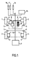
- the vehicle has four wheels, two front wheels 1 and 2 and two rear wheels 3 and 4.
- Each of the wheels is equipped with a wheel speed sensor 5 able to measure the speed instant rotation of the wheel near which it is located.
- the system braking system is a hybrid braking system: the wheels before 1 and 2 are respectively equipped with hydraulic brakes 6 connected to a hydraulic actuator 12 via hydraulic connections 8; the rear wheels 3 and 4 are respectively equipped with brakes electromechanical 7 equipped with electromechanical actuators 9.
- the driver assistance device also includes, in the embodiment of Figure 1, a displacement sensor or depressing degree of the brake pedal 16, a sensor of displacement or degree of depression of the accelerator pedal 17, a sensor for moving the clutch pedal 18 (or a equivalent as a switch on the clutch pedal indicating the slip point) and a lever position sensor of the box of speeds 15.
- the vehicle comprises a longitudinal acceleration sensor 19 of a type comprising an elastically suspended mass.
- the sensor 19 is able to emit a signal corresponding to the instantaneous value of a measured longitudinal acceleration A m of the vehicle.
- the set of sensors described above as well as the 12 hydraulic and 9 electromechanical actuators communicate with a computing unit 11, embedded, through a bus of 13.
- the communications bus 13 may, for example, support the CAN-Bus protocol.
- the calculation unit 11 has all the characteristics electronic and software of a computer.
- the unit of calculation 11 comprises a processor capable of executing instructions in real time and a memory space in which are stored different series of instructions forming executable programs.
- the unit of calculation 11 also includes input / output interfaces necessary for the communication with other elements of the device. These interfaces are able to receive and write in the memory space of the data incoming measurements, such as measurements made by the sensors, and to read in the memory space and to emit outgoing data in the direction actuators.
- the computing unit 11 has more particularly the function of order the brake calipers.
- the calculation unit 11 executes for example of the vehicle behavior control program, such as ABS (anti-lock control), ESP (stability control) or TCS (control Anti-skid).
- the programmable computing unit 11 is particularly suitable to execute the instruction codes of a program of assistance to the driving a vehicle engaged on a slope for the implementation of the process according to the invention.
- This basic process of determining the slope is a step in the process of assisting the driving according to the invention.
- step 20 the speeds ⁇ i of rotation of each of the wheels measured by the different sensors 5 are acquired.
- step 21 a speed V c corresponding to the instantaneous speed of the vehicle is calculated using the wheel speeds ⁇ i .
- various conventional methods well known to those skilled in the art can be used.
- a calculated longitudinal acceleration A c corresponding to an instantaneous acceleration of the vehicle is calculated by time derivative of the calculated speed V c .
- the wheel speed sensors 5 are unsigned sensors, the information they deliver is in fact the absolute value of the wheel speed ⁇ i .
- the calculated velocity V c , calculated in step 21, and the calculated longitudinal acceleration A c , calculated in step 22, are absolute values.
- a step 23 is then provided to determine the sign that must be assigned to the calculated longitudinal acceleration A c according to the ratio of the selected gearbox. This information is given by the sensor 15 giving the position of the speed lever and by the position sensor of the clutch pedal 18 which makes it possible to know if the speed is engaged.
- step 23 if the reverse gear is engaged and the clutch pedal is raised, the sign is assigned to the calculated longitudinal acceleration A c . If the forward gear is engaged and the clutch pedal is raised, the sign + is assigned to the calculated longitudinal acceleration A c . If the gearbox is in neutral or when the clutch pedal is depressed, there are two cases: either the vehicle was moving at the previous moment, in which case we keep the sign corresponding to the last gear that was engaged. ; either the vehicle was stopped at the previous moment, in which case the acceleration sensor or accelerometer 19 is used to determine in which direction the vehicle is starting.
- step 23 is deleted.
- a calculated longitudinal acceleration A c is obtained which has an algebraic value whose sign corresponds to the direction of movement of the vehicle.
- step 24 the instantaneous value of the longitudinal acceleration measured by the acceleration sensor 19 is acquired as a measured longitudinal acceleration A m .
- This measure A m is algebraic.
- step 26 a logical condition of freezing CG slope measurements is tested.
- the CG condition is a Boolean variable with the value 0 when it is unchecked and 1 when it is checked.
- D ds / dt.
- S 2 is a fixed positive stability threshold which can be determined as a result of testing.
- step 28 is performed.
- step 27 is done.
- the value of the slope estimate obtained on iteration previous value is kept as the current value of the slope.
- step 29 indicates the return to step For a new iteration of the slope estimation method p.
- the estimated slope p is an accurate estimate of the slope while during a maneuver. Even though the momentary freezing of the measurement of the slope leads to an error of the estimate, the estimated slope p can, of reliably, used to calculate different control variables. In particular it is used by the computing unit 11 to provide a driving assistance for the descent of a sloping road.
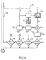
- Figure 3 arranged on two boards for clarity, schematically represents the succession of process steps driving assistance according to the invention. This process is for example implemented by executing a corresponding stored program in the memory space of the computing unit 11.
- the process starts with a plurality of checks of entry conditions allowing, when carried out simultaneously, to get into the main loop 100 of torque determination target braking.
- the first test Test1 consists in checking whether the vehicle is engaged on a slope. In other words, the instantaneous value of the estimated slope p is compared with the value of a first threshold slope p 1 . To go to the next step, p must be greater than p 1 .
- the first threshold slope p 1 is for example 5%.
- step 52 the second test Test2 is to check if the vehicle is stopped. This results in the comparison of the calculated speed V c with a low threshold speed V 1 . To go to the next step, V c must be less than V 1 . In fact, V 1 is not chosen zero because the uncertainties due to the measurements made by the sensors cause V c to fluctuate around zero while the vehicle is actually at a standstill.
- the third test Test3 corresponds to the detection a driver's behavior showing an intention to start.
- the detected behavior is to engage reverse gear, release the brake pedal and do not press, or very weakly, the accelerator pedal. This information is given by the sensors 15, 16 and 17.
- the program enters the main loop 100 for determining a target braking torque ⁇ c . If one of these input conditions is not verified, the calculation unit 11 stops the execution of the program. This will be executed again from the beginning a first predetermined time interval later, for example a few tenths of seconds later.
- the iterations of the main loop are executed periodically at a second predetermined time interval.
- Each iteration of the main loop 100 is indexed by an integer i.
- the main loop starts with a step of determining a desirable speed V 0 .
- the speed that seems to be desirable to descend the slope is determined.
- the desirable speed value V 0 may be a predefined constant reference value, for example 3 km / h -1 .
- the desirable speed value V 0 may depend on the instantaneous value of the slope p: the greater the slope, the more the desirable speed V 0 is reduced; the lower the slope, the more the desirable speed V 0 is increased.
- a corrective term is added to the constant reference value of 3 km / h -1 , the corrective term being proportional to the deviation of the slope p at a reference slope p 0 for example of 5% .
- the conductor can directly influence the value of the desirable speed V 0 . If the driver moves the accelerator pedal beyond a first degree of depression of the acceleration pedal d 1 while remaining below a second degree of depression d 2 , this will be interpreted as the will of the driver. driver to increase the desirable speed V 0 . If in step 152 the degree of depression d is detected in the range limited below by d 1 and higher by d 2 , the desirable speed V 0 of the previous iteration i-1 is increased by a predetermined value ⁇ V 0 to step 154. The desirable speed V 0 will be increased gradually during a succession of iterations. If the degree of depression d is not in the range [d 1 , d 2 ] the value calculated in step 152 is taken into account.
- the memory space 110 of the computing unit 11 has a plurality of calibration tables indexed by a value of speed.
- a calibration table gives the value of the pair of braking to apply on the wheels of the vehicle according to the slope p so that, if the slope was constant, the vehicle actually reaches the speed value serving as an index.
- Each of the calibration tables is obtained in the factory by carrying out tests on a typical vehicle of the range and then memorizing the results obtained in space memory of the unit of calculation of each of the vehicles.
- step 155 the calibration table whose index corresponds to the current value of the desirable speed V 0 , determined at the output of step 151, is selected from the set of calibration tables present in the space memory 110.
- step 156 the instantaneous value of the slope p makes it possible to read on the selected calibration table the value of the theoretical braking torque ⁇ th .
- the value of the theoretical braking torque ⁇ th obtained in step 156 can not be transmitted directly as the target value of the braking torque to the braking control system.
- the theoretical braking torque ⁇ th is the torque to be applied to maintain the speed of the vehicle at the desired speed V 0 .
- the speed of the vehicle given by the calculated speed V c , may be less than the desirable speed V 0 and it is then necessary to apply a target braking torque ⁇ c slightly lower than the theoretical braking torque ⁇ th to increase the speed V c of the vehicle.
- the speed of the vehicle is greater than the desirable speed V 0 , it is necessary to apply a target braking torque ⁇ c slightly greater than the theoretical braking torque ⁇ th to reduce the speed V c of the vehicle.
- the correction torque ⁇ corr is an increasing function of the difference ⁇ V between the desirable speed V 0 and the calculated speed V c .
- step 161 the correction torque ⁇ corr is calculated.
- ⁇ corr is proportional to the deviation ⁇ V and its time derivative.
- step 162 the target braking torque ⁇ c is obtained by subtraction of the correction torque ⁇ corresponding to the theoretical braking torque ⁇ th .
- This current value of the target braking torque ⁇ c is emitted in step 163 in the form, for example, of a signal S ( ⁇ c ) towards the control system of the braking system of the vehicle, moreover known.
- the correction torque ⁇ th is lower than the theoretical torque ⁇ th and the vehicle can take more speed in the slope.
- the Test4 test consists of comparing the value of the calculated speed V c with a high threshold speed V 2, for example of 20 km / h -1 . Indeed, if the driver continuously presses the accelerator pedal, the desirable speed V 0 increases and therefore the speed of descent of the slope also increases. It is not necessary to continue the driving assistance program if the calculated speed V c is greater than the high threshold speed V 2 .
- the Test5 consists in comparing the value of the slope p with a second predetermined slope p 2 . If the vehicle has reached the bottom of the slope, which is characterized by an almost zero slope, it is not necessary to continue the driving assistance program.
- the value of the second predetermined slope p 2 is small to take account of the errors on the calculated value of the slope p.
- a test condition 7 on the brake pedal is tested in step 178. If the driver presses on the brake pedal so as to produce a braking force greater than that recommended by the driver assistance program, ie the braking torque target ⁇ c is that the driver wants to take the hand and stop the vehicle again. If at step 178 this output condition is satisfied, the execution of the program is exited, otherwise a new iteration of the main loop 100 is executed.
- Applicant performed behavioral tests kinematics of a vehicle equipped with the driver assistance device downhill.
- the curve C1 represents the temporal evolution of the value of the slope p determined according to the exposed method
- the curve C3 reproduces the variations of the target braking torque ⁇ c .
- the input condition Test1 is that the vehicle is initially at a standstill.
- the assistance function can then comprise alternatively an initial procedure for the gradual release of the brakes.
- the vehicle driven in the slope by its weight, acquires speed.
- the target braking torque requested by the assistance device becomes greater than the braking torque requested by the initial procedure. From this moment, the assistance device takes control of braking. It is then a question of controlling the vehicle so that the calculated speed V c , represented by the curve C5, tends asymptotically towards the desirable speed V 0 .
- the braking torque to be applied to maintain this speed is constant and corresponds to the theoretical braking torque ⁇ th .
- the curve C4 represents the temporal evolution of the braking torque actually applied to the rear wheels of the vehicle and measured by braking force sensors arranged on the electromechanical calipers.
- the transition corresponds to a significant correction of the theoretical braking torque ⁇ th because the difference between the desirable speed V 0 and the calculated speed V c is important.
- the target braking torque ⁇ c increases gradually with speed. Thus, the driver feels no jerk of the braking system.
- the assistance to the descent of a slope is used when the orientation of the vehicle is such that the front of the vehicle is directed down the slope.
- To activate the assistance mode it is then necessary to test (Test3) if the first gear is engaged.
- the assistance method is advantageously implemented in a vehicle with a hybrid braking system of so that the target braking torque calculated by the assistance method be specifically applied on the only rear wheels.
- the particular characteristics of electromechanical stirrups are used and in particular their silent operation.
Landscapes
- Engineering & Computer Science (AREA)
- Transportation (AREA)
- Mechanical Engineering (AREA)
- Regulating Braking Force (AREA)
- Control Of Driving Devices And Active Controlling Of Vehicle (AREA)
- Vehicle Body Suspensions (AREA)
- Communication Control (AREA)
Priority Applications (6)
| Application Number | Priority Date | Filing Date | Title |
|---|---|---|---|
| EP04290893A EP1584530A1 (de) | 2004-04-05 | 2004-04-05 | Steuerverfahren und -vorrichtung für das Bergabrollen eines Fahrzeugs |
| DE602005014953T DE602005014953D1 (de) | 2004-04-05 | 2005-04-04 | Abwärtsfahrhilfeverfahren und entsprechende vorrichtung |
| AT05749302T ATE433893T1 (de) | 2004-04-05 | 2005-04-04 | Abwärtsfahrhilfeverfahren und entsprechende vorrichtung |
| EP05749302A EP1732794B1 (de) | 2004-04-05 | 2005-04-04 | Abwärtsfahrhilfeverfahren und entsprechende vorrichtung |
| US10/592,577 US7801656B2 (en) | 2004-04-05 | 2005-04-04 | Process for assisting downhill driving and associated device |
| PCT/FR2005/000808 WO2005100109A1 (fr) | 2004-04-05 | 2005-04-04 | Procede d'assistance a la conduite en descente et dispositif associe |
Applications Claiming Priority (1)
| Application Number | Priority Date | Filing Date | Title |
|---|---|---|---|
| EP04290893A EP1584530A1 (de) | 2004-04-05 | 2004-04-05 | Steuerverfahren und -vorrichtung für das Bergabrollen eines Fahrzeugs |
Publications (1)
| Publication Number | Publication Date |
|---|---|
| EP1584530A1 true EP1584530A1 (de) | 2005-10-12 |
Family
ID=34896142
Family Applications (2)
| Application Number | Title | Priority Date | Filing Date |
|---|---|---|---|
| EP04290893A Withdrawn EP1584530A1 (de) | 2004-04-05 | 2004-04-05 | Steuerverfahren und -vorrichtung für das Bergabrollen eines Fahrzeugs |
| EP05749302A Expired - Lifetime EP1732794B1 (de) | 2004-04-05 | 2005-04-04 | Abwärtsfahrhilfeverfahren und entsprechende vorrichtung |
Family Applications After (1)
| Application Number | Title | Priority Date | Filing Date |
|---|---|---|---|
| EP05749302A Expired - Lifetime EP1732794B1 (de) | 2004-04-05 | 2005-04-04 | Abwärtsfahrhilfeverfahren und entsprechende vorrichtung |
Country Status (5)
| Country | Link |
|---|---|
| US (1) | US7801656B2 (de) |
| EP (2) | EP1584530A1 (de) |
| AT (1) | ATE433893T1 (de) |
| DE (1) | DE602005014953D1 (de) |
| WO (1) | WO2005100109A1 (de) |
Cited By (2)
| Publication number | Priority date | Publication date | Assignee | Title |
|---|---|---|---|---|
| FR2987329A1 (fr) * | 2012-02-27 | 2013-08-30 | Bosch Gmbh Robert | Procede d'application de la force de serrage exercee par un frein de stationnement et frein pour sa mise en oeuvre |
| WO2023001287A1 (zh) * | 2021-07-22 | 2023-01-26 | 中国第一汽车股份有限公司 | 陡坡缓降控制方法、系统、车辆和存储介质 |
Families Citing this family (16)
| Publication number | Priority date | Publication date | Assignee | Title |
|---|---|---|---|---|
| WO2006067125A1 (de) * | 2004-12-20 | 2006-06-29 | Continental Teves Ag & Co. Ohg | Anfahrhilfe |
| DE102006039153A1 (de) * | 2006-08-21 | 2008-03-27 | Siemens Ag | Verfahren und Vorrichtung zum Ermitteln einer aktuellen Fahrzeuglängsgeschwindigkeit |
| FR2934831B1 (fr) * | 2008-08-07 | 2010-08-27 | Renault Sas | Procede de desserrage de freins d'un vehicule automobile equipe d'un dispositif d'assistance au demarrage en cote, un tel dispositif d'assistance et vehicule automobile le comportant. |
| US8401753B2 (en) * | 2009-11-23 | 2013-03-19 | Caterpillar Inc. | Automatic downhill speed control system |
| US8589045B2 (en) * | 2011-02-18 | 2013-11-19 | Continental Automotive Systems, Inc | System and method for determining a safe maximum speed of a vehicle |
| KR20130064430A (ko) * | 2011-12-08 | 2013-06-18 | 한국전자통신연구원 | 퓨얼 컷 처리 장치 및 방법 |
| US20130197773A1 (en) * | 2012-01-31 | 2013-08-01 | Jeremy B. Shuler | Descent control of vehicle speed |
| CN103802832A (zh) * | 2012-11-12 | 2014-05-21 | 奥托立夫开发公司 | 坡道起步辅助方法 |
| US8948982B2 (en) | 2013-01-31 | 2015-02-03 | Caterpillar Inc. | Open loop machine motor speed control based on downhill slope determination |
| FR3021280B1 (fr) * | 2014-05-21 | 2017-12-22 | Renault Sas | Procede de controle d'un groupe motopropulseur d'un vehicule, dispositif et vehicule correspondant. |
| JP6973314B2 (ja) * | 2018-07-17 | 2021-11-24 | トヨタ自動車株式会社 | 制御装置、マネージャ、システム、制御方法及び車両 |
| FR3103915B1 (fr) * | 2019-11-29 | 2021-12-17 | Alstom Transp Tech | Procédé d’aide à la conduite d’un véhicule de transport public |
| KR102817285B1 (ko) * | 2020-08-14 | 2025-06-09 | 현대자동차 주식회사 | 수동 변속기 차량의 원격 시동 방법 및 그 장치 |
| US12384333B2 (en) * | 2023-05-16 | 2025-08-12 | Ford Global Technologies, Llc. | Methods for providing correct brake request with a stuck e-pedal |
| GB2633801A (en) * | 2023-09-21 | 2025-03-26 | Jaguar Land Rover Ltd | A control system for controlling a foundation brake and a powertrain of a vehicle |
| IT202300025239A1 (it) * | 2023-11-28 | 2025-05-28 | Brembo Spa | Metodo e relativo sistema per evitare extra-forze nell’azionamento del freno di stazionamento |
Citations (5)
| Publication number | Priority date | Publication date | Assignee | Title |
|---|---|---|---|---|
| WO2001014185A1 (de) * | 1999-08-24 | 2001-03-01 | Continental Teves Ag & Co. Ohg | Verfahren und vorrichtung zur kompensation des hangabtriebs |
| EP1101676A2 (de) * | 1999-11-19 | 2001-05-23 | Toyota Jidosha Kabushiki Kaisha | Verfahren und Vorrichtung zur Regelung der Bremskraft von Kraftfahrzeugen |
| US20020041167A1 (en) * | 2000-07-19 | 2002-04-11 | Honda Giken Kogyo Kabushiki Kaisha | Driving force control system for front-and-rear wheel drive vehicles |
| US6692090B1 (en) * | 1999-03-08 | 2004-02-17 | Continental Teves, Ag & Co. Ohg | Method of maintaining the effect of the engine brake |
| US6701224B1 (en) * | 1999-08-20 | 2004-03-02 | Continental Teves Ag & Co., Ohg | Method for determining that a motor vehicle is climbing or descending a slope |
Family Cites Families (4)
| Publication number | Priority date | Publication date | Assignee | Title |
|---|---|---|---|---|
| US4629043A (en) * | 1983-01-31 | 1986-12-16 | Mazda Motor Corporation | Electric parking brake system for a vehicle |
| GB9420561D0 (en) * | 1994-10-12 | 1994-11-30 | Rover Group | A wheeled vehicle |
| DE19648559B4 (de) * | 1996-11-23 | 2009-01-29 | Wabco Gmbh | Verfahren zur Geschwindigkeitsregelung für ein Fahrzeug im Gefälle |
| EP1557331B1 (de) * | 2002-10-28 | 2011-02-23 | Hitachi Construction Machinery Co., Ltd | Gefällegeschwindigkeitssteuerung |
-
2004
- 2004-04-05 EP EP04290893A patent/EP1584530A1/de not_active Withdrawn
-
2005
- 2005-04-04 DE DE602005014953T patent/DE602005014953D1/de not_active Expired - Lifetime
- 2005-04-04 US US10/592,577 patent/US7801656B2/en active Active
- 2005-04-04 AT AT05749302T patent/ATE433893T1/de not_active IP Right Cessation
- 2005-04-04 WO PCT/FR2005/000808 patent/WO2005100109A1/fr not_active Ceased
- 2005-04-04 EP EP05749302A patent/EP1732794B1/de not_active Expired - Lifetime
Patent Citations (5)
| Publication number | Priority date | Publication date | Assignee | Title |
|---|---|---|---|---|
| US6692090B1 (en) * | 1999-03-08 | 2004-02-17 | Continental Teves, Ag & Co. Ohg | Method of maintaining the effect of the engine brake |
| US6701224B1 (en) * | 1999-08-20 | 2004-03-02 | Continental Teves Ag & Co., Ohg | Method for determining that a motor vehicle is climbing or descending a slope |
| WO2001014185A1 (de) * | 1999-08-24 | 2001-03-01 | Continental Teves Ag & Co. Ohg | Verfahren und vorrichtung zur kompensation des hangabtriebs |
| EP1101676A2 (de) * | 1999-11-19 | 2001-05-23 | Toyota Jidosha Kabushiki Kaisha | Verfahren und Vorrichtung zur Regelung der Bremskraft von Kraftfahrzeugen |
| US20020041167A1 (en) * | 2000-07-19 | 2002-04-11 | Honda Giken Kogyo Kabushiki Kaisha | Driving force control system for front-and-rear wheel drive vehicles |
Cited By (2)
| Publication number | Priority date | Publication date | Assignee | Title |
|---|---|---|---|---|
| FR2987329A1 (fr) * | 2012-02-27 | 2013-08-30 | Bosch Gmbh Robert | Procede d'application de la force de serrage exercee par un frein de stationnement et frein pour sa mise en oeuvre |
| WO2023001287A1 (zh) * | 2021-07-22 | 2023-01-26 | 中国第一汽车股份有限公司 | 陡坡缓降控制方法、系统、车辆和存储介质 |
Also Published As
| Publication number | Publication date |
|---|---|
| WO2005100109A1 (fr) | 2005-10-27 |
| EP1732794A1 (de) | 2006-12-20 |
| ATE433893T1 (de) | 2009-07-15 |
| US7801656B2 (en) | 2010-09-21 |
| EP1732794B1 (de) | 2009-06-17 |
| DE602005014953D1 (de) | 2009-07-30 |
| US20080051968A1 (en) | 2008-02-28 |
Similar Documents
| Publication | Publication Date | Title |
|---|---|---|
| EP1732794B1 (de) | Abwärtsfahrhilfeverfahren und entsprechende vorrichtung | |
| EP1935732B1 (de) | Adaptatives Bremssteurungsverfahren für Fahrzeuge | |
| EP2137043B1 (de) | Verfahren zur unterstützung bei fahrmanövern eines fahrzeugs an einer steigung | |
| EP2137044B1 (de) | Verfahren zur anfahrhilfe an einer steigung und zugehörige vorrichtung | |
| EP2176950B1 (de) | Fahrzeugunterstützungsverfahren | |
| EP1593566A1 (de) | Funktion zur Anfahrunterstützung eines an einer Steigung stehenden Fahrzeuges | |
| EP1621431B1 (de) | Verfahren und Vorrichtung zur Bremskraftverteilung vorne/hinten für ein Kraftfahrzeug | |
| WO2010004178A1 (fr) | Dispositif d'evaluation de l'acceleration transversale d'un vehicule automobile et procede correspondant | |
| FR2858032A1 (fr) | Procede et un dispositif d'assistance au demarrage d'un vehicule automobile arrete sur une surface en pente | |
| EP1621432B1 (de) | Vorrichtung und Verfahren zur Bremssteuerung der Innen- bzw. Aussenräder bei einer Kurvenbremsung | |
| FR2915802A1 (fr) | Procede et systeme de determination d'adherence pour vehicule automobile | |
| FR2919744A1 (fr) | Dispositif de restitution d'efforts pour un stimulateur de conduite. | |
| FR2905107A1 (fr) | Procede de controle de trajectoire d'un vehicule. | |
| EP1593567B1 (de) | Funktion zur Fahrunterstützung während des Verfolgens einer Reihe von Fahrzeugen | |
| EP1791715B1 (de) | Verfahren zur steuerung des mehrbetriebsmodus eines automatikgetriebes für ein kraftfahrzeug, im besonderen für leerlaufbetrieb mit angezogener bremse und dazugehörige vorrichtung | |
| FR2857925A1 (fr) | Procede d'estimation de la pente d'une surface sur laquelle se trouve un vehicule automobile | |
| EP2766232B1 (de) | Sollwertanpassung für eine nutzbremsung | |
| WO2004031011A2 (fr) | Systeme de freinage et procede d'elaboration d'une consigne de deceleration pour actionneurs de frein de vehicule automobile | |
| FR2922026A3 (fr) | Procede d'estimation de la vitesse longitudinale d'un vehicule automobile | |
| EP2074007B1 (de) | Vorrichtung zur geschwindigkeitssteuerung bei einem fahrzeug | |
| FR2856643A1 (fr) | Procede de freinage sans a-coup et dispositif associe | |
| FR2892081A1 (fr) | Dispositif permettant de maintenir un vehicule automobile en place dans une pente, procede d'exploitation d'un tel dispositif et vehicule automobile equipe d'un tel dispositif | |
| EP1982888A1 (de) | Verfahren zur Stabilitätsregelung mit geschlossenem Regelkreis für ein Kraftfahrzeug | |
| FR2934544A3 (fr) | Procede de freinage agissant sur les roues d'un vehicule automobile | |
| EP1938112A1 (de) | Einrichtung zur beschleunigungsmessung in einem kraftfahrzeug |
Legal Events
| Date | Code | Title | Description |
|---|---|---|---|
| PUAI | Public reference made under article 153(3) epc to a published international application that has entered the european phase |
Free format text: ORIGINAL CODE: 0009012 |
|
| AK | Designated contracting states |
Kind code of ref document: A1 Designated state(s): AT BE BG CH CY CZ DE DK EE ES FI FR GB GR HU IE IT LI LU MC NL PL PT RO SE SI SK TR |
|
| AX | Request for extension of the european patent |
Extension state: AL HR LT LV MK |
|
| AKX | Designation fees paid | ||
| REG | Reference to a national code |
Ref country code: DE Ref legal event code: 8566 |
|
| STAA | Information on the status of an ep patent application or granted ep patent |
Free format text: STATUS: THE APPLICATION IS DEEMED TO BE WITHDRAWN |
|
| 18D | Application deemed to be withdrawn |
Effective date: 20060413 |