EP1583127B1 - Schalteranordnung, Relais, Sockel und elektrische Geräte mit einer solchen Anordnung - Google Patents
Schalteranordnung, Relais, Sockel und elektrische Geräte mit einer solchen Anordnung Download PDFInfo
- Publication number
- EP1583127B1 EP1583127B1 EP05354007A EP05354007A EP1583127B1 EP 1583127 B1 EP1583127 B1 EP 1583127B1 EP 05354007 A EP05354007 A EP 05354007A EP 05354007 A EP05354007 A EP 05354007A EP 1583127 B1 EP1583127 B1 EP 1583127B1
- Authority
- EP
- European Patent Office
- Prior art keywords
- switching device
- electrical
- magnet
- base
- base parts
- Prior art date
- Legal status (The legal status is an assumption and is not a legal conclusion. Google has not performed a legal analysis and makes no representation as to the accuracy of the status listed.)
- Expired - Lifetime
Links
Images


Classifications
-
- H—ELECTRICITY
- H01—ELECTRIC ELEMENTS
- H01H—ELECTRIC SWITCHES; RELAYS; SELECTORS; EMERGENCY PROTECTIVE DEVICES
- H01H51/00—Electromagnetic relays
- H01H51/22—Polarised relays
- H01H51/2209—Polarised relays with rectilinearly movable armature
-
- H—ELECTRICITY
- H01—ELECTRIC ELEMENTS
- H01H—ELECTRIC SWITCHES; RELAYS; SELECTORS; EMERGENCY PROTECTIVE DEVICES
- H01H50/00—Details of electromagnetic relays
- H01H50/64—Driving arrangements between movable part of magnetic circuit and contact
-
- H—ELECTRICITY
- H01—ELECTRIC ELEMENTS
- H01H—ELECTRIC SWITCHES; RELAYS; SELECTORS; EMERGENCY PROTECTIVE DEVICES
- H01H1/00—Contacts
- H01H1/58—Electric connections to or between contacts; Terminals
- H01H1/5822—Flexible connections between movable contact and terminal
-
- H—ELECTRICITY
- H01—ELECTRIC ELEMENTS
- H01H—ELECTRIC SWITCHES; RELAYS; SELECTORS; EMERGENCY PROTECTIVE DEVICES
- H01H51/00—Electromagnetic relays
- H01H51/22—Polarised relays
- H01H51/2209—Polarised relays with rectilinearly movable armature
- H01H2051/2218—Polarised relays with rectilinearly movable armature having at least one movable permanent magnet
Definitions
- the invention relates to a switching device comprising a contact block having a fixed part connected to at least one electrical terminal and having at least one electrical contact zone that can collaborate with a contact zone of a mobile part, a device actuator for moving the movable portion from a closed position to an open position of said electrical contact areas.
- the establishment and the cut-off of the electric current at a distance are generally carried out using contactor or relay.
- These widely used devices include in particular electromagnetic actuation means for controlling the displacement of one or more movable contacts relative to one or more fixed contacts, a closed position to an open position and vice versa.
- the actuating means comprise in particular electric coils as well as permanent magnets ( US-B1-6414577 , US Patent 2658971 , EP0686989B1 , EP0272164B1 ).
- these many devices differ among themselves in particular by their number of contacts or the number of positions of the contacts according to the control currents.
- These devices manufactured in large series consist of a housing containing the contacts and the actuating means. Means of connection make it possible to connect the housing with the electrical devices to be controlled.
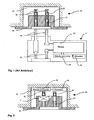
- a known electrical outlet comprises a base 29 disposed in a space 28 of suitable size to receive said base.
- the spaces 28 are arranged in the walls or partitions present in the rooms of the dwelling places.
- the base 29 comprises two sockets 31 in which is inserted an electrical appliance supply socket. These bushings 31 are respectively connected to electrical wires of the mains supply via supply terminals 30. The electrical wires are held at the supply terminals 30 by fixing means 32.
- a relay placed on at least one of the box poles 41 is controlled by a control module 45 receiving in particular control commands for opening or closing the relay by a radio module 46.
- the relay is connected in series between at least one pin 44 and the corresponding socket 31.
- the invention therefore aims to overcome the disadvantages of the state of the art, so as to provide a simple and compact switching device.
- the actuator comprises an electrical coil having a coil for creating a magnetic field for biasing the receptacles with opposite magnetic polarities.
- the actuating device comprises an electric coil having two winding sections connected in series and having opposite winding directions so that said sections respectively create opposite magnetic fields.
- the actuating device comprises two coaxial electrical coils connected so as to create opposite magnetic fields.
- the two bases have the same magnetic polarities.
- the magnet comprises an electrical contact zone in contact with a contact zone connected to a second electrical terminal.
- the magnet in each of the two stable positions, comprises an electrical contact zone in contact with a contact zone connected respectively to a second electrical terminal.
- the magnet operates a magnetic attraction with one of the two bases.
- the metal bases are respectively connected to two separate connection terminals.
- the magnet is electrically connected to one of the two metal bases by a flexible link.
- the magnet is electrically connected to a third electrical terminal by a flexible link.
- the movable magnet moves in a direction parallel to the longitudinal axis of the coils and inside the coils of the actuating device.
- the metal bases have studs positioned projecting on their inner faces, the pads of said bases being placed facing each other and are aligned with the longitudinal axis of the coils.
- a side wall of magnetizable material extends between the two electrically isolated bases.
- a relay according to a development mode of the invention comprises at least two electrical contact terminals and at least two electrical control inputs and comprises a switching device as defined above, the coils of said device being connected to the control inputs and the bases of said device being connected to the contact terminals.
- the resetting means comprise a pressure button acting on the mobile part of the switching device via control means.
- the thermal trigger means comprise a bimetal acting on the movable magnet via control means.
- the thermal tripping means are electrically connected to one of the electrical terminals.
- a control circuit of the actuating device of the switching device as defined above sends a single repulsion control command or two consecutive repulsion and attraction control commands or two simultaneous command orders of attraction and repulsion.
- a socket according to a development mode of the invention comprises a base on which are fixed at least two sockets connected to connection terminals and comprises a switching device as defined above connected between at least one socket and a terminal connection.
- the electrical switching device is a bistable switching device. It can take two stable operating states respectively corresponding to closed or open positions of the electrical terminals A, B.
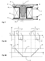
- the switching device 1 consists of a fixed part 2 comprising a first base 22 and a second base 23.
- the two bases 22, 23 of magnetic or magnetizable material, preferably of cylindrical shape, are respectively connected to electrical connection terminals A, B. These terminals A, B are themselves connected to an electrical circuit.
- the two metal bases 22, 23 are electrically insulated from each other.
- the bases are arranged so that their inner faces 24 and 25 are facing each other, for example in parallel.
- the space 10 between the two bases is occupied by an actuating device 5.
- This device is constituted according to the embodiment shown, by an electric coil 55 whose longitudinal axis Y is substantially perpendicular to the inner faces 24, 25 bases 22, 23 of the fixed part 2.
- the electric coil 55 is supplied between two inputs 11 and 12 by a power source capable of sending current commands or electrical pulses.
- This source of impulse energy may consist in particular of a previously charged capacitor.
- the inner faces 24, 25 of the bases 22, 23 are preferably placed as close as possible to the radial faces of the coil 55.
- the outside diameter of the cylindrical bases 22, 23 is advantageously at least equal to the outside diameter of the coil 55.
- said coil in order to obtain an electrical isolation between the bases 22, 23 and the coil 55, said coil is positioned in a support 9 made of electrically insulating material and permeable to the electromagnetic field created by the coil 55 when this last is covered by an electric current I.
- a moving part is positioned in the space delimited by the volume inside the coil 55 of the actuating device 5 and between the internal surfaces of the two bases 22, 23 of the fixed part 2.
- the moving part of the actuating device consists of a permanent magnet 7 connected to one of the two electrical terminals A, B by a flexible link 8.
- This link 8 has both mechanical and electrical characteristics. It allows a translational movement of the magnet 7 in a direction parallel to the longitudinal axis Y of the coil 55 and is used on the other hand as an electrical power conductor between the terminals A and B.
- One of the two bases 22, 23 may have an electrical connection 85 common with the flexible link 8, for example the base 22.
- the base 22 and the link 8 can be connected to an electrical terminal A.
- the flexible link consists of a metal braid of generally cylindrical shape and having one of the ends 26 in conical trunk form.
- the end 26 is in electrical contact with the internal face 24 of the base 22.
- the permanent magnet 7 is fixed on its second end 27 of the flexible link 8.
- the contact zones of the magnet may comprise electrical contact pads.
- the contact pads can be made of usual contact material including copper or silver.
- the end 27 of flexible metal braid is then soldered directly to the electrical contact pad surrounding the magnet 7.
- the displacement of the magnet is effected over a total distance X, hereinafter referred to as the total air gap X.
- the north pole of the magnet is arbitrarily positioned with respect to the internal face 24 of the magnet. 22 base and the south pole of the magnet is opposite the inner face 25 of the base 23.
- the switching device will obviously operate according to the same principles of actuation if the permanent magnet is returned so as to its North Pole is placed opposite with the inner face 25 of the base 23.
- the separation distance of the contact areas is set in order to ensure isolation distances of the product in which the switching device 1 is used.
- the air gap is at least 3 millimeters in the open position.
- the switching device has two stable operating states. A first state of operation where the magnet 7 is attached to the inner face 25 of the base 23. A second state where the magnet is then attached to the inner face 24 of the base 22.
- the actuating device 5 When the coil 55 is not powered, the actuating device 5 is then inoperative. The magnet 7 is then in a first or a second position respectively attached to the base 23 or to the base 22.
- the terminals A and B are electrically connected to one another via the base 22, the flexible link 8, a contact zone of the permanent magnet 7 and the base 23.
- the switching device is then closed .
- terminals A and B are no longer electrically connected because the contact area of the permanent magnet 7 is not in contact with the contact area of the base 23.
- the switching device 1 is then open.
- contact pads may be arranged on the said contact zones of the internal faces of the bases 22, 23.
- the inputs 11 and 12 of the coil 55 are respectively fed so that the current I flowing in the coil 55 produces an electromagnetic field whose field lines, have the effect of magnetizing the bases 22 and 23.
- the base 22 temporarily becomes a North pole while the base 23 becomes a South pole.
- the south poles of the magnet and the base 23 repel with a repulsion force inversely proportional to a distance X1 squared.
- the distance X1 then corresponds to the displacement distance separating the magnet 7 from the base 23.
- the distance X1 tends to zero at the beginning of the displacement and is equal to the total air gap X at the end of displacement.
- the moving magnet moves in the direction 14 in a direction parallel to the longitudinal axis Y of the coil 55.
- the respectively South-South and North-North repulsion forces are of equal intensity and tend to equilibrate.
- the direction of the current I in the coil is then reversed which causes a change in the direction of rotation of the lines of the electromagnetic field produces the coil 55.
- the magnetic polarity of the bases 22, 23 also reverses, the base 22 becomes a South pole and the base 23 becomes a North Pole.
- the North pole of the permanent magnet is then attracted by the base 22.
- the attraction forces between the North and South poles respectively of the magnet and the base 22 are directly proportional to the square of the distance separating them. Thus, more magnet 7 is closer to the base 22 plus the attraction force is large.
- the device can then stop feeding the coil 55.
- the bases 22 and 23 are no longer polarized by the coil and the switching device 1 is found in a new stable state.
- the electrical terminals A, B are no longer electrically connected and the switching device is then open.
- the Figures 8a and 8b represent a chronological diagram of the different stages of operation described above.
- a first cycle C of control commands is sent.
- a first current command or pulse C1 is sent into the coil 55.
- the switching device leaves a first stable state 70.
- the magnet 7 is pushed back from the base 23 and moves towards the second base 22.
- This displacement corresponding to an unstable state of the device, is broken down into two periods respectively represented between instants f and g and between instants g and h.
- the distance X1 traveled by the magnet 7 increases thanks to the repulsion force generated by the first pulse C1 as represented on FIG.
- FIG. figure 5 The inertia of the magnet 7 allows it to travel a distance X1 greater than half of the total air gap X as shown in FIG. figure 6 .
- a second command or pulse C2 sends a current to the coil. I circulating in a contrary direction.
- the supply of the coil is preferably cut off and the device is in a second stable state 72. In this control mode the coil 55 generates a repulsive force followed by an attraction force.
- the second current command or pulse C2 can be suppressed . So when the device is in an intermediate state 71, about the instants g or n, the coil 55 is no longer powered. The magnet 7 will then continue its displacement under the effect of the inertial forces to finally come into contact with the second base. In this case, the control of the coil only generates repulsive forces causing the displacement of the magnet 7. At the end of the stroke, the attraction of the magnet 7 on the bases of magnetic or magnetizable materials occurs without the action of the coil.
- the device as represented on the Figures 3 to 7 is particularly intended for electric remote switches.
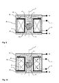
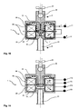
- studs 13 are arranged projecting on the inner faces of the bases 22 and 23. This structure reduces the length of the permanent magnet while keeping the same length of the total air gap X. This in particular reduces costs of the permanent magnet 7.
- a side wall of magnetizable material 60 extends between the two bases 22, 23.
- an insulating portion 9 is interposed between the bases.
- the actuating device 5 comprises a coil 55 whose winding is made in two sections 56, 57.
- the winding of the wire on the first section 56 is in a first direction of rotation and the winding of the wire on the second section 57 is in a second direction of rotation opposite to the first.
- the lengths of the two windings are substantially equal.
- the operating mode of the device is then the following. Chronologically, as shown on the Figures 13a and 13b at an instant e, before sending an order to the actuating device 5, said device is in a first stable state 70.
- a first control command C1 is sent to the coil 55 via the inputs 11, 12.
- the local electromagnetic fields created by the two winding sections 56, 57 of the coil 55 make it possible to magnetize the bases 22 and 23 with identical magnetic poles.
- the two winding sections respectively create local magnetic fields whose field lines 62, 63 rotate in opposite directions.
- the base 22 and the base 23 become South poles.
- a repulsion force is generated between the South pole of the magnet 7 and the South pole of the base 23. This force tends to push the magnet which is in contact with the inner face 25 of the base 23 according to the direction 14.
- a force of attraction is generated between the North pole of the magnet 7 and the South pole of the base 22. This force tends to attract the magnet towards the base 22.
- the switching device 1 then leaves the first stable state 70.
- the magnet 7 pushed back from the first base, begins to move toward the second base. This displacement, corresponding to an unstable state of the device, between the instants f and h1.
- the terminals A, B are then open and the device is in an open stable state 72. Then, at time h2, the supply of the coil can then be cut off and the bases are no longer polarized by said coil.
- the duration of the pulse C1 between the instants f and h2 is then advantageously greater than the duration of the total travel of the magnet 7 moving from the first base to the second base.
- a second control command C2 is sent at a time m.
- the direction of the electric current I flowing in the coil 55 is then reversed as shown in FIG. figure 12 .
- the north pole of the magnet which is in contact with the inner face of the base 22 is pushed back along the direction 14.
- the magnet 7 is attracted by the base 23.
- the terminals A, B are again in the closed position. Then, the supply of the coil 55 can then be cut off at the instant 02 and the bases 22, 23 are no longer polarized by said coil.
- the Figures 15 to 18 represent embodiments of the switching device 1 for use in a socket 29 of a socket 40.
- the bases 22, 23 of the switching device 1 then comprise respectively a socket 31 and a power supply terminal 30.
- the power supply terminals 30 comprise means 32 for fixing the cables or supply wires.
- an alternative embodiment of the actuating device 5 comprises two coils 58, 59 adjacent and electrically connected.
- the winding of the winding wire of these two coils 58, 59 generate opposite magnetic fields.
- the lengths of the two windings are substantially equal.
- the electrical inputs 11, 12 of the actuating device are respectively connected to the coils 58 and 59.
- the operation of this variant is similar to that of the first preferred embodiment as shown in FIGS. Figures 10 to 12 and described above.
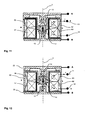
- the actuating device 5 comprises two coils 58, 59 adjacent and electrically independent.
- the coils 58, 59 are respectively electrically powered between inputs 11a, 12a and 11b, 12b.
- the winding direction of the winding wire of the two coils 58, 59 as well as the choice of electrical polarity of the inputs 11a, 11b, 12a and 12b makes it possible to move the magnet 7 of the base 22 towards the base 23 and reciprocally .
- the winding directions of the winding wire of the two coils 58, 59 are opposite and the lengths of the two windings are substantially equal.
- the device is in a first stable state 70, the terminals A and B are in the open position.
- the operating mode of the device is then as follows.
- a first control command or pulse C11 is sent to the coil 58, the terminals 11a and 12a are respectively fed negatively and positively.
- the electric current I flowing in the coil 58 generates a local magnetic field. Said field makes it possible to magnetize the pad 13 of the base 22.
- the stud of the base 22 then becomes a North pole.
- the base 23 has no magnetic polarity.
- a repulsion force is generated between the North pole of the magnet and the North pole of the base 22. This force tends to push the magnet which is in contact with the inner face 24 of the base 22.
- the magnet is subjected to an electromagnetic force which tends to cause it to move in the direction of travel 14.
- the magnet After moving between the two bases, the magnet is positioned on the base 23, the terminals A, B are then closed. The supply of the coils can then be cut off, the magnetic pole of the base 22 disappears. The device is in a closed stable state 72 with the magnet in contact with the base 23.
- a second control command C22 is sent to the second coil 59 as shown in FIG. figure 19B .
- the terminals 11b and 12b are respectively powered respectively positively and negatively.
- the electric current I flowing in the coil 59 generates a local magnetic field. Said field makes it possible to magnetize the stud 13 of the base 23.
- the stud of the base 23 then becomes a South pole.
- the base 22 has no magnetic polarity.
- a repulsion force is generated between the south pole of the magnet and the south pole of the base 23. This force tends to push the magnet which is in contact with the inner face 25 of the base 23. magnet is subjected to an electromagnetic force which tends to cause it to move in the direction of travel 14.
- the magnet After moving between the two bases, the magnet is positioned on the base 22, the terminals A, B are then open. The supply of the coils can then be cut off, the magnetic pole of the base 23 disappears. The device is in an open stable state 70 with the magnet in contact with the base 22.
- a single control command C11 or C22 is sent to only one of the two coils 58 or 59.
- the flexible link 8 is connected to a third electrical terminal C distinct from the terminals A and B.
- An additional electrical insulator 99 is then used to separate the flexible link 8 from the base 22 on which the link was previously fixed.
- the magnet then has two electrical contact areas that can collaborate respectively with the two bases 22, 23.
- the displacement of the movable portion 2, in particular of the magnet 7 from a first stable position to a second stable position allows successively connecting terminals A and C and terminals C and B.
- the electrical terminals are soldered to a printed circuit board 101 serving to support a cover 100 enclosing the switching device 1 said inverter.
- the devices as represented on the Figures 10 to 20 are particularly intended for so-called bistable electrical relays.
- an electrical apparatus comprises a switching device 1 and thermal triggering means 73 as well as resetting means 80.
- the thermal tripping means 73 make it possible to open the terminals A and B in the event of an electrical overload of the switching device 1. They include a bimetal 75 associated with a control pin 76.
- bimetal 75 can be connected directly to one of the electrical terminals B of the switching device 1.
- the bimetallic strip 75 may not be in electrical contact with the electrical terminals A, B.
- a coil 81 surrounding the bimetal strip 75 is then connected directly to one of the electrical terminals B.
- the control shaft 76 is an electrical insulator. A first end of said axis is permanently connected to the bimetal 75.
- the longitudinal axis of the control axis 76 is preferably coincident with the longitudinal axis Y of the coils 58, 59.
- the control axis 76 is slidably mounted through one of the bases, preferably the base 23.
- a passage of an excessive electric current inside the bimetallic strip 75 or inside the coil 81 causes heating of said bimetallic strip and therefore its deformation.
- This deformation of the bimetal 75 is transmitted to the control shaft 76 via its first end and causes a translational movement of said axis 76 in a direction parallel to the longitudinal axis Y of the coils 58, 59.
- the second end of said axis may be in contact with said magnet.
- the mechanical resetting means 80 make it possible to manually close the terminals A and B when the magnet is on the base 22.
- the mechanical resetting means 80 comprise a pressure button 77 which can act on a second control axis 79 by intermediate elastic means 78. A first end of the second control axis 79 is permanently connected to the elastic means 78.
- the longitudinal axis of the control axis 79 is preferably coincident with the longitudinal axis Y of the coils 58 , 59.
- the control shaft 79 is slidably mounted through one of the bases, preferably the base 22. An action on the pressure button 77 is transmitted to the control shaft 79 via its first end and causes a movement in translation of said axis 79 in a direction parallel to the longitudinal axis Y of the coils 58, 59.
- the figure 21 represents the device in stable operating position. Terminals A and B are then closed, bimetal 75 has not undergone any deformation due to any heating.
- bimetal 75 When the device is subjected to an electrical overload, bimetal 75 is deformed as shown in FIG. figure 22 . This deformation of the bimetal 75 then tends to cause the control pin 76 to move towards the magnet 7. An increasing separation force FB then applies to the magnet 7 via the control pin 76. force FB tends to oppose the magnetic attraction force FA of the magnet on the first base 23. The force FA directly depends on the intrinsic characteristics of the magnet 7.
- the release force FB is much lower than the magnetic attraction force FA.
- the FB force increases. Beyond a certain deformation, the intensity of the force FB becomes much greater than the force FA and causes a sudden detachment of the magnet 7 of the first base 22. As shown in FIG. figure 23 the magnet 7 will stick on the second base 22. The switching device 1 is then open.
- the rearming of the device can be done through two types of means.
- the elastic means 78 When the pressure button 77 is depressed, the elastic means 78 having undergone deformation exert a compression force FP on the second control axis 79. This compression force FP then acts directly on the magnet 7 which is on the base 22 and tends to take off the latter.
- the stiffness of the elastic means 78 is calibrated so as to be able to take off the magnet 7 from the base 22 when the force FB exerted on the magnet 7 by the first transmission axis 76 is minimal. In other words, if the bimetal 75 has not returned to its original shape and still exerts a force FB on the magnet 7 via the control shaft 76, the mechanical resetting means 80 are inoperative.
- bimetal 75 will cool down and return to its original shape.
- the detachment force FB tends to zero.
- This type of device then comprises two types of rearming.
- the switching device 1 also retains its original remote opening and closing control functions.
- the electrical control of the coils 58 and 59 can be made remotely while the mechanical resetting means 80 are preferably controlled by an operator located next to the device.
- an electrical apparatus comprises a switching device 1 and thermal triggering means.
- This type of device is particularly intended to be used as a thermal circuit breaker or as an electric thermostat.
- the thermal triggering means 82 allow terminals A and B to be opened if the ambient temperature of the medium in which the device is located increases.
- the thermal tripping means 82 are associated with a control axis 76. As in the previous example, the deformation of the thermal triggering means 82 due to an increase in the temperature causes a displacement of the control axis 76 which acts on the moving part, in particular the magnet 7 of the switching device 1.
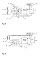
- FIGS. 28 and 29 represent alternative embodiments of a control module 45 of the actuating device 5.
- the control module 45 is in particular intended to control switching devices according to the Figures 10 to 12 . It comprises a circuit 88 composed of four power transistors 91 mounted in a known manner in H. The coils 56, 57 are connected to said transistors. The transistors 91 are controlled via a control circuit 87 powered by a source 86 and receiving control commands from a reception module 46.
- the control module 45 is in particular intended to control switching devices according to the Figures 16 to 18 . It comprises a circuit 88 composed of two power transistors 91 connected respectively to the coils 58 and 59. The transistors are controlled via a control circuit 87 supplied by a source 86 and receiving these control commands from a receiving module 46.
- the switching device 1 may be intended for the control of electrical outlets 40.
- the figure 2 represents an electrical socket in which has been placed a switching device 1 according to the embodiments of the invention. Said switching device 1 is placed respectively between the bushings 31 and the supply terminals 30 and thus makes it possible to cut simultaneously or separately the two electrical poles of the socket 40.
- a control module 45 placed in the volume 28 and supplied between the terminals 30 makes it possible to control the opening or closing of the switching device 1.
- External commands for electrical control of the switching devices can be received in particular by receiving modules 46 connected to the control module 45. External commands can also be transmitted by other means such as the carrier currents.
Landscapes
- Physics & Mathematics (AREA)
- Electromagnetism (AREA)
- Electromagnets (AREA)
- Relay Circuits (AREA)
- Switch Cases, Indication, And Locking (AREA)
- Connections Arranged To Contact A Plurality Of Conductors (AREA)
Claims (21)
- Bistabile Schaltvorrichtung (1) mit einem Kontaktblock, der ein feststehendes Teil, welches mit mindestens einer Anschlussklemme verbunden ist und mindestens eine elektrische Kontaktzone aufweist, die mit einer Kontaktzone eines beweglichen Teils verbunden werden kann, sowie eine Betätigungseinrichtung (5) umfasst, mit der das bewegliche Teil von einer Einschaltstellung in eine Ausschaltstellung der genannten elektrischen Kontaktzonen überführt werden kann, dadurch gekennzeichnet, dass• das bewegliche Teil eine Betätigungseinrichtung (5) mit mindestens einer elektromagnetischen Spule (55, 58, 59) umfasst, die zwischen zwei aus einem magnetischen oder magnetisierbaren Werkstoff bestehenden und elektrisch gegeneinander isolierten Grundplatten (22, 23) angeordnet ist, wobei die elektromagnetische(n) Spule(n) (55, 58, 59) in der Lage ist(sind), die genannten Grundplatten (22, 23) zu magnetisieren,• das bewegliche Teil mindestens einen beweglichen Magneten (7) umfasst, der im Inneren der mindestens einfach vorhandenen elektromagnetischen Spule (55, 58, 59) angeordnet ist und mindestens eine elektrische Kontaktzone aufweist, die mit einer ersten Anschlussklemme (A, C) elektrisch verbunden ist, wobei• sich der bewegliche Magnet (7) von einer Grundplatte zur anderen, zwischen zwei stabilen, jeweils einem anderen elektrischen Zustand der Schaltvorrichtung (1) entsprechenden Stellungen verschiebt,• und der genannte bewegliche Magnet (7) in mindestens einer der stabilen Stellungen elektrisch in Kontakt mit einer der Grundplatten (22, 23) steht, welche mit einer zweiten Anschlussklemme (22, 23) verbunden ist.
- Schaltvorrichtung nach Anspruch 1, dadurch gekennzeichnet, dass die Betätigungseinrichtung (5) eine elektromagnetische Spule (55) mit einer Wicklung umfasst, die dazu dient, ein magnetisches Feld (62, 63) zur Magnetisierung der Grundplatten (22, 23) mit entgegengesetzten magnetischen Polaritäten zu erzeugen.
- Schaltvorrichtung nach Anspruch 1, dadurch gekennzeichnet, dass die Betätigungseinrichtung eine elektromagnetische Spule (55) mit zwei Wicklungsabschnitten (56, 57) umfasst, die in Reihe geschaltet sind und entgegensetzte Wicklungssinne aufweisen, derart dass die genannten Wicklungsabschnitte entgegengerichtete Magnetfelder (62, 63) erzeugen.
- Schaltvorrichtung nach Anspruch 1, dadurch gekennzeichnet, dass die Betätigungseinrichtung (5) zwei koaxial zueinander angeordnete elektromagnetische Spulen (58, 59) umfasst, die so zusammengeschaltet sind, dass sie einander entgegengerichtete Magnetfelder (62, 63) erzeugen.
- Schaltvorrichtung nach Anspruch 3 oder 4, dadurch gekennzeichnet, dass die Grundplatten (22, 23) die gleiche magnetische Polung aufweisen.
- Schaltvorrichtung nach irgendeinem der vorhergehenden Ansprüche, dadurch gekennzeichnet, dass in einer der stabilen Stellungen der Magnet (7) eine elektrische Kontaktzone aufweist, die mit einer Kontaktzone elektrisch in Kontakt steht, welche mit einer zweiten Anschlussklemme (B) verbunden ist.
- Schaltvorrichtung nach irgendeinem der vorhergehenden Ansprüche, dadurch gekennzeichnet, dass in jeder der stabilen Stellungen der Magnet (7) eine elektrische Kontaktzone aufweist, die mit einer Kontaktzone elektrisch in Kontakt steht, welche jeweils mit einer zweiten Anschlussklemme (A, B) verbunden ist.
- Schaltvorrichtung nach irgendeinem der vorhergehenden Ansprüche, dadurch gekennzeichnet, dass der Magnet (7) in jeder der stabilen Stellungen eine magnetische Anziehungskraft auf eine der Grundplatten (22, 23) ausübt.
- Schaltvorrichtung nach Anspruch 1, dadurch gekennzeichnet, dass die beiden metallischen Grundplatten (22, 23) mit zwei unterschiedlichen Anschlussklemmen (A, B) verbunden sind.
- Schaltvorrichtung nach Anspruch 9, dadurch gekennzeichnet, dass der Magnet (7) über eine flexible Verbindung (8) mit einer der metallischen Grundplatten (22, 23) elektrisch verbunden ist.
- Schaltvorrichtung nach Anspruch 9, dadurch gekennzeichnet, dass der Magnet (7) über eine flexible Verbindung (8) mit einer dritten Anschlussklemme (C) elektrisch verbunden ist.
- Schaltvorrichtung nach irgendeinem der vorhergehenden Ansprüche, dadurch gekennzeichnet, dass sich der bewegliche Magnet innerhalb der Spulen (55, 58, 59) der Betätigungseinrichtung parallel zur Längsachse (Y) der Spulen (55, 58, 59) verschiebt.
- Schaltvorrichtung nach irgendeinem der vorhergehenden Ansprüche, dadurch gekennzeichnet, dass die metallischen Grundplatten (22, 23) aus ihrer Innenseite (24, 25) herausstehende Vorsprünge (13) aufweisen, welche Vorsprünge (13) der genannten Grundplatten einander gegenüber liegen und mit der Längsachse (Y) der Spulen (55, 58, 59) fluchten.
- Schaltvorrichtung nach irgendeinem der vorhergehenden Ansprüche, dadurch gekennzeichnet, dass zwischen den beiden elektrisch gegeneinander isolierten Grundplatten (22, 23) eine Seitenwand aus einem magnetisierbaren Werkstoff (60) angeordnet ist.
- Relais mit mindestens zwei Kontaktklemmen (A, B, C) und mindestens zwei elektrischen Steuereingängen (11, 12, 12a, 12b), dadurch gekennzeichnet, dass es eine Schaltvorrichtung (1) nach den vorhergehenden Ansprüche umfasst, wobei die Spulen (55, 58, 59) der genannten Schaltvorrichtung mit den Steuereingängen (11, 12, 11a, 12b) und die Grundplatten (22, 23) der genannten Vorrichtung mit den Kontaktklemmen (A, B) verbunden sind.
- Elektrisches Schaltgerät mit thermischen Auslösemitteln (73) und Rückstellmitteln (80), dadurch gekennzeichnet, dass es eine den thermischen Auslösemitteln (73) und den Rückstellmitteln (80) zugeordnete Schaltvorrichtung (1) nach irgendeinem der Ansprüche 1 bis 14 umfasst.
- Elektrisches Schaltgerät nach Anspruch 16, dadurch gekennzeichnet, dass die Rückstellmittel (80) einen Drucktaster (77) umfassen, der über Steuermittel (79) auf das bewegliche Teil der Schaltvorrichtung (1) wirkt.
- Elektrisches Schaltgerät nach Anspruch 16, dadurch gekennzeichnet, dass die thermischen Auslösemittel (73) ein Bimetall (75) umfassen, das über Steuermittel (76) auf den beweglichen Magneten (7) wirkt.
- Elektrisches Schaltgerät nach Anspruch 16, dadurch gekennzeichnet, dass die thermischen Auslösemittel (73) elektrisch mit einer der Anschlussklemmen (B) verbunden sind.
- Steckdose (40) mit einem Sockel (29), auf dem mindestens zwei mit Anschlussklemmen (A, B) verbundene Buchsen (31) befestigt sind, dadurch gekennzeichnet, dass die Steckdose eine Schaltvorrichtung (1) nach irgendeinem der Ansprüche 1 bis 14 umfasst, welche zwischen mindestens eine Buchse (31) und eine Anschlussklemme (30) geschaltet ist.
- Steckdose (40) nach Anspruch 20, dadurch gekennzeichnet, dass sie ein mit den Steuereingängen (11, 12) der Betätigungseinrichtung (5) der Schaltvorrichtung (1) verbundenes Steuermodul (45) umfasst, welches Steuermodul (45) ein einzelnes Rückstoß-Steuersignal oder zwei aufeinander folgende Rückstoß- und Anzugs-Steuersignale oder zwei gleichzeitige Rückstoß- und Anzugs-Steuersignale aussendet.
Applications Claiming Priority (2)
| Application Number | Priority Date | Filing Date | Title |
|---|---|---|---|
| FR0403433 | 2004-04-01 | ||
| FR0403433A FR2868595B1 (fr) | 2004-04-01 | 2004-04-01 | Dispositif de commutation electrique, relais, prise de courant et appareils electriques comportant un tel dispositif |
Publications (2)
| Publication Number | Publication Date |
|---|---|
| EP1583127A1 EP1583127A1 (de) | 2005-10-05 |
| EP1583127B1 true EP1583127B1 (de) | 2010-01-06 |
Family
ID=34878481
Family Applications (1)
| Application Number | Title | Priority Date | Filing Date |
|---|---|---|---|
| EP05354007A Expired - Lifetime EP1583127B1 (de) | 2004-04-01 | 2005-02-10 | Schalteranordnung, Relais, Sockel und elektrische Geräte mit einer solchen Anordnung |
Country Status (7)
| Country | Link |
|---|---|
| US (1) | US7283027B2 (de) |
| EP (1) | EP1583127B1 (de) |
| CN (1) | CN100573770C (de) |
| AT (1) | ATE454704T1 (de) |
| AU (1) | AU2005201590B2 (de) |
| DE (1) | DE602005018705D1 (de) |
| FR (1) | FR2868595B1 (de) |
Families Citing this family (9)
| Publication number | Priority date | Publication date | Assignee | Title |
|---|---|---|---|---|
| US7936242B2 (en) * | 2007-09-14 | 2011-05-03 | William N Carpenter | Magnetically operated electrical switch |
| US8861167B2 (en) | 2011-05-12 | 2014-10-14 | Global Plasma Solutions, Llc | Bipolar ionization device |
| EP2551871A1 (de) * | 2011-07-29 | 2013-01-30 | ABB Technology AG | Kontaktscheibe mit Gewebeband |
| GB2503989A (en) * | 2012-05-31 | 2014-01-15 | Art Sea Ind Company Ltd | A thermostat having a bi-metallic element |
| DE102012107281B4 (de) * | 2012-08-08 | 2014-03-06 | Eto Magnetic Gmbh | Bistabile elektromagnetische Stellvorrichtung, Ankerbaugruppe sowie Nockenwellenverstellvorrichtung |
| CN103337425A (zh) * | 2013-05-28 | 2013-10-02 | 宁波市镇海怡福莱文化创意有限公司 | 一种电磁直驱保护器 |
| US10372021B2 (en) | 2014-12-31 | 2019-08-06 | Anthony S Lenzo | Triple axis magnetic actuator through non-metallic substrate |
| CN108515937A (zh) * | 2017-02-28 | 2018-09-11 | 刘书林 | 带遥控式车用隐形防盗器的车用电动油泵 |
| CN220367856U (zh) * | 2023-08-03 | 2024-01-19 | 东莞市中汇瑞德电子股份有限公司 | 继电器 |
Citations (2)
| Publication number | Priority date | Publication date | Assignee | Title |
|---|---|---|---|---|
| US2658971A (en) * | 1948-09-17 | 1953-11-10 | Fkg Fritz Kesselring Geratebau | Electric contact device |
| US2859297A (en) * | 1954-10-28 | 1958-11-04 | Boeing Co | Magnetically self-returning ball armature relays |
Family Cites Families (8)
| Publication number | Priority date | Publication date | Assignee | Title |
|---|---|---|---|---|
| GB1098145A (en) * | 1966-10-21 | 1968-01-10 | Standard Telephones Cables Ltd | Electromagnetic relays |
| FR2606927B1 (fr) * | 1986-11-19 | 1991-09-13 | Telemecanique Electrique | Electro-aimant polarise bistable |
| US5272458A (en) * | 1988-07-28 | 1993-12-21 | H-U Development Corporation | Solenoid actuator |
| DE3942542A1 (de) * | 1989-12-22 | 1991-06-27 | Lungu Cornelius | Bistabiler magnetantrieb mit permanentmagnetischem hubanker |
| US5883557A (en) * | 1997-10-31 | 1999-03-16 | General Motors Corporation | Magnetically latching solenoid apparatus |
| FR2792108B1 (fr) * | 1999-04-12 | 2001-05-04 | Schneider Electric Sa | Electroaimant a courant continu |
| US6414577B1 (en) * | 2000-02-14 | 2002-07-02 | Jerzy Hoffman | Core with coils and permanent magnet for switching DC relays, RF microwave switches, and other switching applications |
| US7138894B2 (en) * | 2005-01-25 | 2006-11-21 | Mei-Ling Lo | Electromagnetic breaker |
-
2004
- 2004-04-01 FR FR0403433A patent/FR2868595B1/fr not_active Expired - Fee Related
-
2005
- 2005-02-10 EP EP05354007A patent/EP1583127B1/de not_active Expired - Lifetime
- 2005-02-10 AT AT05354007T patent/ATE454704T1/de not_active IP Right Cessation
- 2005-02-10 DE DE602005018705T patent/DE602005018705D1/de not_active Expired - Fee Related
- 2005-03-17 US US11/081,756 patent/US7283027B2/en not_active Expired - Fee Related
- 2005-03-30 CN CNB2005100639406A patent/CN100573770C/zh not_active Expired - Lifetime
- 2005-03-31 AU AU2005201590A patent/AU2005201590B2/en not_active Expired
Patent Citations (2)
| Publication number | Priority date | Publication date | Assignee | Title |
|---|---|---|---|---|
| US2658971A (en) * | 1948-09-17 | 1953-11-10 | Fkg Fritz Kesselring Geratebau | Electric contact device |
| US2859297A (en) * | 1954-10-28 | 1958-11-04 | Boeing Co | Magnetically self-returning ball armature relays |
Also Published As
| Publication number | Publication date |
|---|---|
| CN100573770C (zh) | 2009-12-23 |
| CN1677602A (zh) | 2005-10-05 |
| EP1583127A1 (de) | 2005-10-05 |
| AU2005201590A1 (en) | 2005-10-20 |
| FR2868595B1 (fr) | 2013-10-18 |
| US7283027B2 (en) | 2007-10-16 |
| DE602005018705D1 (de) | 2010-02-25 |
| US20050219022A1 (en) | 2005-10-06 |
| FR2868595A1 (fr) | 2005-10-07 |
| AU2005201590B2 (en) | 2009-07-23 |
| ATE454704T1 (de) | 2010-01-15 |
Similar Documents
| Publication | Publication Date | Title |
|---|---|---|
| EP1556873B1 (de) | Elektrische schaltvorrichtung, relais sowie elektrisches gerät mit einer solchen vorrichtung | |
| EP2936534B1 (de) | Modulare elektrische schaltvorrichtung mit mindestens einer einpoligen absperreinheit und schalteranordnung mit solchen vorrichtungen | |
| US5977858A (en) | Electro-thermal bi-stable actuator | |
| EP1583127B1 (de) | Schalteranordnung, Relais, Sockel und elektrische Geräte mit einer solchen Anordnung | |
| CN100375211C (zh) | 真空断路器 | |
| FR2928501A1 (fr) | Dispositif de generation d'energie a deux parties mobiles | |
| FR2999781A1 (fr) | Dispositif modulaire de commutation electrique comportant au moins un bloc de coupure unipolaire et ensemble de commutation comportant de tels dispositifs. | |
| EP2779190A1 (de) | Einheitsschaltblock und Schaltvorrichtung, die mindestens einen solchen Block umfasst | |
| EP1185995B1 (de) | Steuervorrichtung zum öffnen und/oder zum schliessen, insbesondere für ein schaltgerät wie ein schutzschalter, und ein schutzschalter ausgerüstet mit dieser vorrichtung | |
| FR2642223A1 (fr) | Actionneur a solenoide ameliore | |
| FR2598027A1 (fr) | Appareil contacteur inverseur protege conte les surintensites de courant | |
| FR2661041A1 (fr) | Commutateur magnetique pour lignes coaxiales de transmission. | |
| FR2953661A1 (fr) | Dispositif generateur d'energie electrique | |
| WO2009138603A1 (fr) | Interrupteur de protection mixte electromecanique / semi-conducteur | |
| EP1901320A1 (de) | Kontaktvorrichtung für ein Elektrogerät und Elektrogerät mit derartiger Vorrichtung | |
| EP2192605B1 (de) | Trennvorrichtung eines elektrischen Schaltkreises und Stromverteilungskasten, der mit einer solchen Trennvorrichtung ausgestattet ist | |
| EP2936526B1 (de) | Verfahren zum einstellen des kompressionsverlaufs elektrischer kontakte in einem abgeschirmten block, block zur durchführung dieses verfahrens und schaltvorrichtung mit einem derartigen block | |
| EP0204594A1 (de) | Gegen Kurzschlussströme geschütztes Schaltgerät | |
| FR2758903A1 (fr) | Systeme inverseur de marche, notamment pour contacteur- disjoncteur | |
| EP2936536A1 (de) | Modulare elektrische schaltvorrichtung mit mindestens einer einpoligen trenneinheit und schaltungsanordnung mit solchen vorrichtungen | |
| FR2999780A1 (fr) | Dispositif modulaire de commutation electrique comportant au moins un bloc de coupure unipolaire et ensemble de commutation comportant de tels dispositifs. | |
| EP0061382B1 (de) | Elektromagnetisches Relais mit gleichgültiger Arbeitslage | |
| EP2517027A1 (de) | Phasenstrommessmodul für einen stromzähler mit einer stromabschaltfunktion | |
| FR3102292A1 (fr) | Appareil de protection d’une installation électrique en courant alternatif | |
| FR2666927A1 (fr) | Relais electromagnetique. |
Legal Events
| Date | Code | Title | Description |
|---|---|---|---|
| PUAI | Public reference made under article 153(3) epc to a published international application that has entered the european phase |
Free format text: ORIGINAL CODE: 0009012 |
|
| AK | Designated contracting states |
Kind code of ref document: A1 Designated state(s): AT BE BG CH CY CZ DE DK EE ES FI FR GB GR HU IE IS IT LI LT LU MC NL PL PT RO SE SI SK TR |
|
| AX | Request for extension of the european patent |
Extension state: AL BA HR LV MK YU |
|
| RIN1 | Information on inventor provided before grant (corrected) |
Inventor name: GARELLI, OLEGSCHNEIDER ELECTRIC INDUSTRIES SAS Inventor name: BATTEUX, PIERRE,SCHNEIDER ELECTRIC INDUSTRIES SAS |
|
| 17P | Request for examination filed |
Effective date: 20060202 |
|
| AKX | Designation fees paid |
Designated state(s): AT BE BG CH CY CZ DE DK EE ES FI FR GB GR HU IE IS IT LI LT LU MC NL PL PT RO SE SI SK TR |
|
| 17Q | First examination report despatched |
Effective date: 20060303 |
|
| RAP1 | Party data changed (applicant data changed or rights of an application transferred) |
Owner name: SCHNEIDER ELECTRIC INDUSTRIES SAS |
|
| GRAP | Despatch of communication of intention to grant a patent |
Free format text: ORIGINAL CODE: EPIDOSNIGR1 |
|
| GRAS | Grant fee paid |
Free format text: ORIGINAL CODE: EPIDOSNIGR3 |
|
| GRAA | (expected) grant |
Free format text: ORIGINAL CODE: 0009210 |
|
| AK | Designated contracting states |
Kind code of ref document: B1 Designated state(s): AT BE BG CH CY CZ DE DK EE ES FI FR GB GR HU IE IS IT LI LT LU MC NL PL PT RO SE SI SK TR |
|
| REG | Reference to a national code |
Ref country code: GB Ref legal event code: FG4D Free format text: NOT ENGLISH |
|
| REG | Reference to a national code |
Ref country code: CH Ref legal event code: EP |
|
| REG | Reference to a national code |
Ref country code: IE Ref legal event code: FG4D |
|
| REF | Corresponds to: |
Ref document number: 602005018705 Country of ref document: DE Date of ref document: 20100225 Kind code of ref document: P |
|
| REG | Reference to a national code |
Ref country code: NL Ref legal event code: VDEP Effective date: 20100106 |
|
| PG25 | Lapsed in a contracting state [announced via postgrant information from national office to epo] |
Ref country code: SI Free format text: LAPSE BECAUSE OF FAILURE TO SUBMIT A TRANSLATION OF THE DESCRIPTION OR TO PAY THE FEE WITHIN THE PRESCRIBED TIME-LIMIT Effective date: 20100106 |
|
| LTIE | Lt: invalidation of european patent or patent extension |
Effective date: 20100106 |
|
| PG25 | Lapsed in a contracting state [announced via postgrant information from national office to epo] |
Ref country code: AT Free format text: LAPSE BECAUSE OF FAILURE TO SUBMIT A TRANSLATION OF THE DESCRIPTION OR TO PAY THE FEE WITHIN THE PRESCRIBED TIME-LIMIT Effective date: 20100106 |
|
| PG25 | Lapsed in a contracting state [announced via postgrant information from national office to epo] |
Ref country code: ES Free format text: LAPSE BECAUSE OF FAILURE TO SUBMIT A TRANSLATION OF THE DESCRIPTION OR TO PAY THE FEE WITHIN THE PRESCRIBED TIME-LIMIT Effective date: 20100417 Ref country code: LT Free format text: LAPSE BECAUSE OF FAILURE TO SUBMIT A TRANSLATION OF THE DESCRIPTION OR TO PAY THE FEE WITHIN THE PRESCRIBED TIME-LIMIT Effective date: 20100106 Ref country code: PT Free format text: LAPSE BECAUSE OF FAILURE TO SUBMIT A TRANSLATION OF THE DESCRIPTION OR TO PAY THE FEE WITHIN THE PRESCRIBED TIME-LIMIT Effective date: 20100506 Ref country code: IS Free format text: LAPSE BECAUSE OF FAILURE TO SUBMIT A TRANSLATION OF THE DESCRIPTION OR TO PAY THE FEE WITHIN THE PRESCRIBED TIME-LIMIT Effective date: 20100506 Ref country code: NL Free format text: LAPSE BECAUSE OF FAILURE TO SUBMIT A TRANSLATION OF THE DESCRIPTION OR TO PAY THE FEE WITHIN THE PRESCRIBED TIME-LIMIT Effective date: 20100106 |
|
| REG | Reference to a national code |
Ref country code: IE Ref legal event code: FD4D |
|
| BERE | Be: lapsed |
Owner name: SCHNEIDER ELECTRIC INDUSTRIES SAS Effective date: 20100228 |
|
| PG25 | Lapsed in a contracting state [announced via postgrant information from national office to epo] |
Ref country code: PL Free format text: LAPSE BECAUSE OF FAILURE TO SUBMIT A TRANSLATION OF THE DESCRIPTION OR TO PAY THE FEE WITHIN THE PRESCRIBED TIME-LIMIT Effective date: 20100106 Ref country code: FI Free format text: LAPSE BECAUSE OF FAILURE TO SUBMIT A TRANSLATION OF THE DESCRIPTION OR TO PAY THE FEE WITHIN THE PRESCRIBED TIME-LIMIT Effective date: 20100106 |
|
| REG | Reference to a national code |
Ref country code: CH Ref legal event code: PL |
|
| PG25 | Lapsed in a contracting state [announced via postgrant information from national office to epo] |
Ref country code: CY Free format text: LAPSE BECAUSE OF FAILURE TO SUBMIT A TRANSLATION OF THE DESCRIPTION OR TO PAY THE FEE WITHIN THE PRESCRIBED TIME-LIMIT Effective date: 20100106 Ref country code: IE Free format text: LAPSE BECAUSE OF FAILURE TO SUBMIT A TRANSLATION OF THE DESCRIPTION OR TO PAY THE FEE WITHIN THE PRESCRIBED TIME-LIMIT Effective date: 20100106 Ref country code: GR Free format text: LAPSE BECAUSE OF FAILURE TO SUBMIT A TRANSLATION OF THE DESCRIPTION OR TO PAY THE FEE WITHIN THE PRESCRIBED TIME-LIMIT Effective date: 20100407 Ref country code: EE Free format text: LAPSE BECAUSE OF FAILURE TO SUBMIT A TRANSLATION OF THE DESCRIPTION OR TO PAY THE FEE WITHIN THE PRESCRIBED TIME-LIMIT Effective date: 20100106 Ref country code: CH Free format text: LAPSE BECAUSE OF NON-PAYMENT OF DUE FEES Effective date: 20100228 Ref country code: SE Free format text: LAPSE BECAUSE OF FAILURE TO SUBMIT A TRANSLATION OF THE DESCRIPTION OR TO PAY THE FEE WITHIN THE PRESCRIBED TIME-LIMIT Effective date: 20100106 Ref country code: MC Free format text: LAPSE BECAUSE OF NON-PAYMENT OF DUE FEES Effective date: 20100301 Ref country code: LI Free format text: LAPSE BECAUSE OF NON-PAYMENT OF DUE FEES Effective date: 20100228 Ref country code: RO Free format text: LAPSE BECAUSE OF FAILURE TO SUBMIT A TRANSLATION OF THE DESCRIPTION OR TO PAY THE FEE WITHIN THE PRESCRIBED TIME-LIMIT Effective date: 20100106 |
|
| PLBE | No opposition filed within time limit |
Free format text: ORIGINAL CODE: 0009261 |
|
| STAA | Information on the status of an ep patent application or granted ep patent |
Free format text: STATUS: NO OPPOSITION FILED WITHIN TIME LIMIT |
|
| PG25 | Lapsed in a contracting state [announced via postgrant information from national office to epo] |
Ref country code: BG Free format text: LAPSE BECAUSE OF FAILURE TO SUBMIT A TRANSLATION OF THE DESCRIPTION OR TO PAY THE FEE WITHIN THE PRESCRIBED TIME-LIMIT Effective date: 20100406 Ref country code: SK Free format text: LAPSE BECAUSE OF FAILURE TO SUBMIT A TRANSLATION OF THE DESCRIPTION OR TO PAY THE FEE WITHIN THE PRESCRIBED TIME-LIMIT Effective date: 20100106 Ref country code: CZ Free format text: LAPSE BECAUSE OF FAILURE TO SUBMIT A TRANSLATION OF THE DESCRIPTION OR TO PAY THE FEE WITHIN THE PRESCRIBED TIME-LIMIT Effective date: 20100106 |
|
| 26N | No opposition filed |
Effective date: 20101007 |
|
| GBPC | Gb: european patent ceased through non-payment of renewal fee |
Effective date: 20100406 |
|
| PG25 | Lapsed in a contracting state [announced via postgrant information from national office to epo] |
Ref country code: DK Free format text: LAPSE BECAUSE OF FAILURE TO SUBMIT A TRANSLATION OF THE DESCRIPTION OR TO PAY THE FEE WITHIN THE PRESCRIBED TIME-LIMIT Effective date: 20100106 |
|
| PG25 | Lapsed in a contracting state [announced via postgrant information from national office to epo] |
Ref country code: BE Free format text: LAPSE BECAUSE OF NON-PAYMENT OF DUE FEES Effective date: 20100228 Ref country code: DE Free format text: LAPSE BECAUSE OF NON-PAYMENT OF DUE FEES Effective date: 20100901 |
|
| PG25 | Lapsed in a contracting state [announced via postgrant information from national office to epo] |
Ref country code: IT Free format text: LAPSE BECAUSE OF FAILURE TO SUBMIT A TRANSLATION OF THE DESCRIPTION OR TO PAY THE FEE WITHIN THE PRESCRIBED TIME-LIMIT Effective date: 20100106 Ref country code: GB Free format text: LAPSE BECAUSE OF NON-PAYMENT OF DUE FEES Effective date: 20100406 |
|
| PG25 | Lapsed in a contracting state [announced via postgrant information from national office to epo] |
Ref country code: HU Free format text: LAPSE BECAUSE OF FAILURE TO SUBMIT A TRANSLATION OF THE DESCRIPTION OR TO PAY THE FEE WITHIN THE PRESCRIBED TIME-LIMIT Effective date: 20100707 Ref country code: LU Free format text: LAPSE BECAUSE OF NON-PAYMENT OF DUE FEES Effective date: 20100210 |
|
| PG25 | Lapsed in a contracting state [announced via postgrant information from national office to epo] |
Ref country code: TR Free format text: LAPSE BECAUSE OF FAILURE TO SUBMIT A TRANSLATION OF THE DESCRIPTION OR TO PAY THE FEE WITHIN THE PRESCRIBED TIME-LIMIT Effective date: 20100106 |
|
| REG | Reference to a national code |
Ref country code: FR Ref legal event code: PLFP Year of fee payment: 12 |
|
| REG | Reference to a national code |
Ref country code: FR Ref legal event code: PLFP Year of fee payment: 13 |
|
| REG | Reference to a national code |
Ref country code: FR Ref legal event code: PLFP Year of fee payment: 14 |
|
| PGFP | Annual fee paid to national office [announced via postgrant information from national office to epo] |
Ref country code: FR Payment date: 20240226 Year of fee payment: 20 |