EP0204594A1 - Gegen Kurzschlussströme geschütztes Schaltgerät - Google Patents
Gegen Kurzschlussströme geschütztes Schaltgerät Download PDFInfo
- Publication number
- EP0204594A1 EP0204594A1 EP86400936A EP86400936A EP0204594A1 EP 0204594 A1 EP0204594 A1 EP 0204594A1 EP 86400936 A EP86400936 A EP 86400936A EP 86400936 A EP86400936 A EP 86400936A EP 0204594 A1 EP0204594 A1 EP 0204594A1
- Authority
- EP
- European Patent Office
- Prior art keywords
- switch
- opening
- case
- arc
- contact
- Prior art date
- Legal status (The legal status is an assumption and is not a legal conclusion. Google has not performed a legal analysis and makes no representation as to the accuracy of the status listed.)
- Granted
Links
- 239000004020 conductor Substances 0.000 claims description 9
- 230000001681 protective effect Effects 0.000 claims description 4
- 230000005540 biological transmission Effects 0.000 claims description 3
- 238000001514 detection method Methods 0.000 claims 1
- 238000004146 energy storage Methods 0.000 claims 1
- 230000005284 excitation Effects 0.000 claims 1
- 230000000694 effects Effects 0.000 description 4
- 238000012790 confirmation Methods 0.000 description 3
- 238000006073 displacement reaction Methods 0.000 description 3
- 210000000056 organ Anatomy 0.000 description 3
- 238000005192 partition Methods 0.000 description 3
- 238000010008 shearing Methods 0.000 description 3
- 230000000295 complement effect Effects 0.000 description 2
- 230000005520 electrodynamics Effects 0.000 description 2
- 239000007789 gas Substances 0.000 description 2
- 238000002955 isolation Methods 0.000 description 2
- 238000004804 winding Methods 0.000 description 2
- 241000238876 Acari Species 0.000 description 1
- 230000001687 destabilization Effects 0.000 description 1
- 238000010586 diagram Methods 0.000 description 1
- 230000005288 electromagnetic effect Effects 0.000 description 1
- 238000009434 installation Methods 0.000 description 1
- 239000011810 insulating material Substances 0.000 description 1
- 239000012212 insulator Substances 0.000 description 1
- 239000000463 material Substances 0.000 description 1
- 239000002184 metal Substances 0.000 description 1
- 238000000034 method Methods 0.000 description 1
- 238000009527 percussion Methods 0.000 description 1
- 238000010926 purge Methods 0.000 description 1
- 238000000926 separation method Methods 0.000 description 1
- 230000009466 transformation Effects 0.000 description 1
Images


Classifications
-
- H—ELECTRICITY
- H02—GENERATION; CONVERSION OR DISTRIBUTION OF ELECTRIC POWER
- H02H—EMERGENCY PROTECTIVE CIRCUIT ARRANGEMENTS
- H02H7/00—Emergency protective circuit arrangements specially adapted for specific types of electric machines or apparatus or for sectionalised protection of cable or line systems, and effecting automatic switching in the event of an undesired change from normal working conditions
- H02H7/22—Emergency protective circuit arrangements specially adapted for specific types of electric machines or apparatus or for sectionalised protection of cable or line systems, and effecting automatic switching in the event of an undesired change from normal working conditions for distribution gear, e.g. bus-bar systems; for switching devices
- H02H7/222—Emergency protective circuit arrangements specially adapted for specific types of electric machines or apparatus or for sectionalised protection of cable or line systems, and effecting automatic switching in the event of an undesired change from normal working conditions for distribution gear, e.g. bus-bar systems; for switching devices for switches
-
- H—ELECTRICITY
- H01—ELECTRIC ELEMENTS
- H01H—ELECTRIC SWITCHES; RELAYS; SELECTORS; EMERGENCY PROTECTIVE DEVICES
- H01H89/00—Combinations of two or more different basic types of electric switches, relays, selectors and emergency protective devices, not covered by any single one of the other main groups of this subclass
- H01H89/06—Combination of a manual reset circuit with a contactor, i.e. the same circuit controlled by both a protective and a remote control device
- H01H2089/065—Coordination between protection and remote control, e.g. protection job repartition, mutual assistance or monitoring
-
- H—ELECTRICITY
- H01—ELECTRIC ELEMENTS
- H01H—ELECTRIC SWITCHES; RELAYS; SELECTORS; EMERGENCY PROTECTIVE DEVICES
- H01H9/00—Details of switching devices, not covered by groups H01H1/00 - H01H7/00
- H01H9/30—Means for extinguishing or preventing arc between current-carrying parts
- H01H9/32—Insulating body insertable between contacts
-
- H—ELECTRICITY
- H01—ELECTRIC ELEMENTS
- H01H—ELECTRIC SWITCHES; RELAYS; SELECTORS; EMERGENCY PROTECTIVE DEVICES
- H01H9/00—Details of switching devices, not covered by groups H01H1/00 - H01H7/00
- H01H9/30—Means for extinguishing or preventing arc between current-carrying parts
- H01H9/46—Means for extinguishing or preventing arc between current-carrying parts using arcing horns
- H01H9/465—Shunt circuit closed by transferring the arc onto an auxiliary electrode
Definitions
- the invention relates to a protective switch device or system comprising between the two connection terminals respectively connected to the electrical network and to a load, on the one hand, a first switch which is controlled by an electromagnet and which is suitable establishing and frequently interrupting the nominal current of the load, on the other hand, a second switch with automatic opening having properties for limiting fault currents such as those of short circuits, so as to protect the lines and prevent damage to the first switch.
- limiting switches can be fuses, mechanical quick-opening switches comparable to those of circuit breakers, automatic opening switches. ticks which exploit repulsive forces, or insulating screen switches in which the latter operates a rapid shear of the arc.
- the invention therefore proposes to provide a combined device such as that whose general constitution is defined above, robust means capable of transferring a significant fraction of the overload current in a parallel channel.
- the aim is achieved thanks to the fact that in the vicinity of the contacts of the second switch is arranged a transfer electrode isolated from them, which is connected to the potential of a connection terminal of the first switch by a conductor placed in parallel thereon, and which is capable of presenting with the contact of this second switch being connected to the other connection terminal and at the time of its opening, a transfer path ionized by the initial arc appearing at the time of opening.
- an insulating screen is placed between the contacts of the second switch to move the medium ionized by the initial arc towards the transfer electrode; in a second embodiment which is derived from the previous one, and which is more particularly capable of protecting the first switch, the initial arc is completely destabilized by a throttling or shearing effect which the screen operates on it; in a third embodiment which is more particularly capable of operating a protection of the lines, respectively of the load, the same screen operates a complete destabilization of the transfer arc; finally, in a last embodiment intended to improve the results obtained above, the energy of the initial arc is used to operate a very rapid propulsion of the insulating screen.
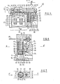
- a protective switch device or system 1 (visible in FIG. 1), comprises, in an insulating box 2 able to be fixed on a support 3, a plurality of internal circuits such as 4, which each lead to two connection terminals such as 5 and 6, and include in series a switch device of the contactor type 7, which is capable of being controlled by an electromagnet 8, and a protection switch device 9 of the current limiting type with automatic opening when the appearance of abnormally high currents such as those occurring during short circuits.
- This device 9 comprises a transfer electrode 10 which is placed in the vicinity of the contacts of the switch 9 and a bypass conductor 10 . which connects this electrode to the potential of terminal 5; the latter is connected for example to the RST supply network, while the opposite terminal 6 is connected, for example, to a load 11. If the device is intended to be installed in a polyphase network, there are as many circuits 4 arranged 10a that of phases and a single electromagnet 8 simultaneously operates the control of the multiple switches 7.
- a switch with automatic opening can, for example, and preferably, open under the effect of significant repulsive forces which develop between its fixed and moving parts; in this case, magnetizable parts known per se, such as parallel branches of a U-shaped circuit, can be associated with them with the supports of the movable contacts to combine with repulsion forces, those coming from electromagnetic effects. which act in the same direction of opening of the movable contact.
- the contacts 13 and 12 are respectively one fixed, the other mobile, and the transfer electrode 10 which is located in the vicinity of these two contacts is placed so that an initial arc Ai , appearing between these contacts at the time of their opening, establishes during the displacement of the movable contact 12 a deformable ionized zone extending to this electrode 10 so that a bypass arc Ad is established between it and the contact 12 and the initial arc goes out.
- the very large current which passed or would have passed through the switch 7 therefore flows through the bypass conductor 10, see Figures 14 and 15. a
- FIG. 2 there is between the contacts 16, 17 of the second switch 18 and in their vicinity, an insulating screen 19 which is inserted between them at high speed as soon as they open; at the end of a certain movement, the screen conducts the initial arc Ai towards a zone 20 suitable for its transfer to the electrode 21 connected as before to the bypass conductor 10?
- the initial arc will then be sheared by the screen (or respectively by an edge of an opening of the screen) against an insulating wall 22, after, thanks to the presence of the already ionized atmosphere, an arc of bypass Ad has sprung between the movable contact 17 and the electrode 21; this last arc then goes out, for example, due to an elongation due to the movement of the mobile contact or traction, on metal fins which cool it.
- the screen preferably operates a complete isolation between the contacts 16, 17 and 21, 17, for example by covering insulating surfaces, using baffles in the housing, etc.
- the same screen 25 operates successively the displacement of the initial arc Ai coming from the fixed contacts 24 and mobile 29, its transfer to the bypass electrode 26, the shearing of the initial arc against a first surface 27, and the shearing of the derived arc Ad against a second insulating surface or groove 28 of the housing, in order to protect the first switch and operate rapid line protection; the contact 24 and the electrode 26 can be aligned according to the direction of movement of the screen, see FIG. 3, or placed transversely, the edge of the screen being for example inclined relative to this direction, see FIG. 4.
- a winding 161 is placed in series in the circuit 4; this winding very quickly attracts a pallet or a core 162 when very high currents appear and the movement of this is communicated to the screen 14 as soon as the contacts 12 and 13 are open.
- a spring 166 previously armed the ends of which rest on the housing 171 and on the screen 14 is released when a lock or catch 167 carried by the movable contact 168 releases an edge of the screen by allowing it to slide very quickly between the contacts 168, 169; in this embodiment, magnetizable parts such as 170 cooperate with the movable contact to add their effects to those of the repulsion forces to produce the initial separation.
- FIG. 5 A more detailed embodiment of a protective switch device 35 according to the invention is visible in FIG. 5, where, for example, in the same housing 38, a contactor device 36 which is located in the left region 37 of a body of this figure, is associated with a protection limiting device 39 which is located in a contiguous region 40.
- the energy necessary for moving the screen, here tubular is borrowed from that which is developed by the appearance of the initial arc Ai.
- a control electromagnet comprising the fixed yoke 42, the coil 43, the movable armature 44 and its return spring 45; an insulating contact carrier 46 which is made integral with the armature, carries in each of the windows such as 47 a multiplicity of parallel columns such as 48, a movable contact bridge 49 equipped with contact pads 50, 51 and its contact pressure spring 52.
- Two fixed contacts 54, 53 are carried by conductive supports 56 respectively 55, one of which includes a connection terminal 57 accessible from the outside; this terminal corresponds to that which is mentioned at 5 in FIG. 1, while the contact bridge and the fixed contacts correspond to the switch 7.
- the protection limiting device 39 comprises, see FIG. 6, a switch 61 corresponding to that bearing the reference 9 in FIG. 1, which comprises a fixed contact 62 carried by a conductive support piece 63 and a movable contact 64 carried by a oscillating lever 65 sensitive parallel and conductive ment being connected by a flexible braid 66 to a second terminal 67 of the apparatus which corresponds to that shown at 6 in FIG. 1.
- the members 64, 65, 66 are located in a cavity 68 of the body 70 terminating to a cylindrical housing 71; this cavity contains in particular a magnetizable part 72 in the shape of a U, the parallel branches of which such as 73 surround the contact lever 65; the latter receives the elastic forces of a contact pressure spring 74 to close the switch in the rest position.
- the conductive support 63 is either backed against an insulating support 75 which is made integral, by means not shown, with a partition or the bottom 76 of the body 70 of the device, be contained within this support. In both cases, this support integral with the bottom 76 enters the housing 71.
- this support the cross section of which can take a substantially circular shape, see FIG. 7, there is a case 77 made of insulating material preferably having a cylindrical shape of revolution, which slides with little play in a cylindrical housing 71; the bottom 150 of this case is placed in the housing 71.
- the movable contact 64 passes through an opening 78 common to the housing and to the cavity, and penetrates through an opening 79 of the case to bear against the fixed contact.
- the end 80 of the conductive support 63, opposite the fixed contact, is connected to the fixed contact support 55 which can, for this purpose, be shaped like the opposite terminal 57 of the switch 7.
- the housing is connected to the atmosphere in its lower part 81 close to the base 82 by vents such as 83 and 84, see also FIG. 6. These vents serve, on the one hand, to purge the air which is in this lower part, when the case moves down, and allow, on the other hand, ionized gases which develop in a volume 85 existing between the case and the support 75 during an opening of the switch to escape the atmos sphere by the openings 78, 79 and / or by another opening 86 of the case when the case abuts against a partition 87 of the case possibly serving as a plug for the housing.
- vents such as 83 and 84, see also FIG. 6.
- a conductive transfer electrode 90 which first circulates substantially parallel to the contact support 63, being isolated from the latter and crossing for example the support 75, then joins the terminal 57 by the conductor 91, for example crossing one of the insulating partitions 92 which separate two switches such as 7 neighbors.
- This transfer electrode has an internal free end 93, which is close to the two contacts 62, 64 and which leads to a volume 88 connected to the previous 85.
- Means which hold the case in the rest position can take the form of springs, or lateral elastic rims capable of moving away and disappearing out of the housing.
- orientation means not shown, but the embodiment of which is obvious, allow the case to keep the same angular orientation, so that reset means not shown give it after an operation of opening, a new rest position identical to the previous one.
- this apparatus corresponds to that of the preceding apparatuses, namely that the appearance of a significant overcurrent in the circuit placed between the terminals 57, 67 first causes the opening of the limiter switch 61 when the lever 65 is, on the one hand, repelled by the electrodynamic forces developed between it and the support 63 and, on the other hand, attracted towards the bottom of the magnetizable part 72; the initial arc, which arises at this time, causes an increase in pressure in the volumes 88, 85, so that the case moves very quickly down the figure, and that the edge 94 of its opening 79 moves the arc and the ionized zone around it to the transfer electrode 90, 93; when the resistance of this initial arc is greater than that of a transfer arc which can be fixed between the electrode 93 and the movable contact 64, the latter appears and this initial arc disappears, while the movement of the case causes the transferred arc to shear when the edge of the opening overlaps with the edge 96 of the cavity which limits the opening 79.
- the latter 100 comprises a contact lever 101, a movable contact 102, a cavity 103 and an edge 104 identical to the previous.
- the fixed contact 105 is here represented by a conductive piece, possibly tubular, placed on the external surface of a fixed insulating support piece 106, which is traversed by a conductor 107 substantially coaxial including an extension 108, surrounded laterally by a jacket insulator 117, axially exceeds the position of this fixed contact.
- the tubular case 109 which can slide with suitable reduced play around the support piece and inside the housing 110, has on its side skirt 111 an opening 112 which is placed, in the rest position, facing the fixed contact to let the mobile contact pass 102.
- This case has on its front wall 113 a second opening 114 which surrounds the insulated portion 108 in the rest position.
- An uninsulated end 116 of the extension 108, which represents the transfer electrode, is therefore insulated by a baffled path from the contacts fixed and mobile for the rest position of the case, shown in this figure.
- the initial arc between the contacts 105, 102 is therefore gradually displaced towards the transfer electrode 116, until a zone of ionized gases simultaneously bathes this electrode and the movable contact, and when a transfer arc is established between them.
- This initial arc is in turn sheared by the covering of the opening 112 and of the wall or edge 104 which limits the cavity 110.
- the extension 108a of the transfer electrode 116a is not not insulated by an insulating jacket secured to the insulating part 106a, but by a tubular jacket 121 which is carried by the internal face 122 of the bottom 113 a of the case 109a and which enters a recess 123 of this insulating part 106a in establishing in the rest position shown, isolation baffles; in this embodiment, where the transfer path is shorter than previously, the operation is identical to that which has been described.
- a stretching of the transfer arc Ad can be established by a particular conformation visible in FIG. 10, where the case has already moved, and in which the jacket 125 extends more deeply at the interior of a recess 126 of the part 106 b .
- This case here comprises a lateral opening 127, which allows the transfer arc Ad to be established, but the edge 128 of which obliges the latter to stretch during the movement in direction F of the case 109 b .
- the opening of the limiter switch 39 has interrupted the supply of the load, one may wish to confirm this opening of the circuit by opening the contactor 36 placed in series; in this case, a switch 139 can be placed in series in the supply circuit of the coil 43 of the electromagnet 41, the opening of which will be established for example by moving the case, see FIG. arrangements must be made for this switch is only opened when the initial arc Ai is extinguished.
- a drawer 154 can also be used either to prohibit the control of the contactor, or by means of the implementation of a provision with cam 151 and rocker arm 152, see FIG. 13, causing the manual opening of the movable contact of the limit switch 9 for the purpose of sectioning the line in a stable "sectioned" position S.
- the rearming of the cases can be operated using 'a manually operated drawer 130, see Figure 11, the handle 131 of which is placed on the front face 132 of the device 133, see also Figure 12; a hook 134 placed at the end of a rod 135 integral with this handle, and being located opposite the front face 136 of the case 137 in the bottom of a housing 138 having a depth allowing an additional stroke of this case, allows to communicate to the latter a movement going from position T towards position R, after an operation caused by an overcurrent.
- a confirmation switch 139 can be established by means of this drawer both in the direction of its opening and in the direction of its closing, by means of a cam or ramp 147 integral with the rod 135; in this case, the drawer must be able to take three positions, one "normal” N, stable, for which the confirmation switch 139 is closed, the other "tripped” D, also stable, close to or confused with position S, for which this drawer has been pushed a little further by the percussion of the cases 137 against the hook 134 and where the switch 139 is open, and the third of "reset” RE, preferably unstable, for which the drawer 130 returns the cases to the R position, before returning to the N position if necessary using an elastic return means.
- the contactor 36 and the limiter 39 can be arranged in particular boxes 140 respectively 141 which can be mechanically associated.
- the terminals 55 and 80 which are respectively carried by these two boxes, as well as transfer terminals 142 and removable conductors such as 143, making it possible to establish the circuit 10 a of FIG. 1 or 91 of FIG. 5 parallel to a straight A passing through two opposite terminals, will advantageously be arranged in the vicinity of the front faces 144, 145 in channels 149, cells or insulated chambers 146, 147 set back relative to these faces to receive terminals 80.
- the opening confirmation switch il or i 2 (which is equivalent to that represented at 139 in FIG. 11) can be placed, either in the vicinity of the switch 9 to shorten the transmission means which control it, either in the vicinity of the electromagnet 8 to shorten the coil supply circuit and avoid the presence of local connection terminals when the device is constituted by the assembly of two boxes.
Landscapes
- Arc-Extinguishing Devices That Are Switches (AREA)
- Emergency Protection Circuit Devices (AREA)
- Amplifiers (AREA)
- Supplying Of Containers To The Packaging Station (AREA)
- Control Of Motors That Do Not Use Commutators (AREA)
- Vehicle Body Suspensions (AREA)
- Measurement And Recording Of Electrical Phenomena And Electrical Characteristics Of The Living Body (AREA)
- Electric Propulsion And Braking For Vehicles (AREA)
- Breakers (AREA)
- Switches That Are Operated By Magnetic Or Electric Fields (AREA)
- Percussion Or Vibration Massage (AREA)
- Switch Cases, Indication, And Locking (AREA)
- Devices That Are Associated With Refrigeration Equipment (AREA)
- Protection Of Static Devices (AREA)
Priority Applications (1)
| Application Number | Priority Date | Filing Date | Title |
|---|---|---|---|
| AT86400936T ATE41263T1 (de) | 1985-05-06 | 1986-04-29 | Gegen kurzschlussstroeme geschuetztes schaltgeraet. |
Applications Claiming Priority (2)
| Application Number | Priority Date | Filing Date | Title |
|---|---|---|---|
| FR8507163A FR2581477B1 (fr) | 1985-05-06 | 1985-05-06 | Appareil interrupteur protege contre les courants de court-circuit |
| FR8507163 | 1985-05-06 |
Publications (2)
| Publication Number | Publication Date |
|---|---|
| EP0204594A1 true EP0204594A1 (de) | 1986-12-10 |
| EP0204594B1 EP0204594B1 (de) | 1989-03-08 |
Family
ID=9319183
Family Applications (1)
| Application Number | Title | Priority Date | Filing Date |
|---|---|---|---|
| EP86400936A Expired EP0204594B1 (de) | 1985-05-06 | 1986-04-29 | Gegen Kurzschlussströme geschütztes Schaltgerät |
Country Status (13)
| Country | Link |
|---|---|
| US (1) | US4733031A (de) |
| EP (1) | EP0204594B1 (de) |
| JP (1) | JPS61256542A (de) |
| AT (1) | ATE41263T1 (de) |
| BR (1) | BR8602010A (de) |
| CA (1) | CA1249621A (de) |
| CH (1) | CH667942A5 (de) |
| DE (1) | DE3615340A1 (de) |
| ES (1) | ES8705154A1 (de) |
| FR (1) | FR2581477B1 (de) |
| GB (2) | GB2175450B (de) |
| IT (1) | IT1189102B (de) |
| ZA (1) | ZA863378B (de) |
Cited By (6)
| Publication number | Priority date | Publication date | Assignee | Title |
|---|---|---|---|---|
| FR2611095A1 (fr) * | 1987-02-13 | 1988-08-19 | Telemecanique Electrique | Systeme d'alimentation telecommandee et de protection electriques coordonnees d'appareils electriques |
| EP0317660A1 (de) * | 1987-11-25 | 1989-05-31 | Square D Company (Deutschland) Gmbh | Schütz |
| EP0418734A2 (de) * | 1989-09-18 | 1991-03-27 | Allen-Bradley Company, Inc. | Verfahren und Vorrichtung zum Schutz von Anlassern von Fehlerströmen |
| EP0465694A1 (de) * | 1990-07-09 | 1992-01-15 | Siemens Aktiengesellschaft | Schalteinrichtung |
| EP0633584A1 (de) * | 1993-07-05 | 1995-01-11 | Schneider Electric Sa | Elektrischer Schutz- und Reglervorrichtung für elektrische Last |
| EP0649157A1 (de) * | 1993-10-15 | 1995-04-19 | Schneider Electric Sa | Elektrischer Schutzvorrichtung mit Lastschalter und Effektor |
Families Citing this family (3)
| Publication number | Priority date | Publication date | Assignee | Title |
|---|---|---|---|---|
| DE3824027A1 (de) * | 1988-07-15 | 1990-01-18 | Asea Brown Boveri | Elektrisches schaltgeraet |
| JPH03129627A (ja) * | 1989-09-18 | 1991-06-03 | Mitsubishi Electric Corp | 限流形回路遮断器 |
| US5753877A (en) * | 1996-02-20 | 1998-05-19 | Eaton Corporation | Circuit breaker terminal tubulator protection assembly for diverting discharged ionized gasses |
Citations (3)
| Publication number | Priority date | Publication date | Assignee | Title |
|---|---|---|---|---|
| GB2086658A (en) * | 1980-10-30 | 1982-05-12 | Asea Ab | Electric switch |
| EP0104981A1 (de) * | 1982-09-17 | 1984-04-04 | Merlin Gerin | Elektrischer Schalter mit einer ferngesteuerten ruhenden Schaltvorrichtung |
| EP0118333A1 (de) * | 1983-02-04 | 1984-09-12 | Telemecanique | Schalter mit einer sich beim Ausschalten zwischen den Kontakten einschiebenden Isolierstoffwand und mit Lichtbogenabquetschmittel zwischen der Isolierstoffwand und einem Isolierstoffgehäuse |
Family Cites Families (8)
| Publication number | Priority date | Publication date | Assignee | Title |
|---|---|---|---|---|
| JPS4838379U (de) * | 1971-09-10 | 1973-05-11 | ||
| JPS549003Y2 (de) * | 1972-05-10 | 1979-04-25 | ||
| JPS5242268A (en) * | 1975-09-30 | 1977-04-01 | Matsushita Electric Works Ltd | Circuit breaker |
| US4164719A (en) * | 1978-04-03 | 1979-08-14 | Gould Inc. | Load management apparatus for residential load centers |
| US4258343A (en) * | 1979-02-12 | 1981-03-24 | Gould Inc. | Unitized combination starter |
| JPS592052B2 (ja) * | 1980-01-19 | 1984-01-17 | 株式会社明電舎 | バス制御方法 |
| JPS5925143A (ja) * | 1982-07-30 | 1984-02-09 | 松下電工株式会社 | 回路しや断器に於ける消弧装置 |
| JPS59105226A (ja) * | 1982-12-09 | 1984-06-18 | 株式会社日立製作所 | しゃ断器 |
-
1985
- 1985-05-06 FR FR8507163A patent/FR2581477B1/fr not_active Expired
-
1986
- 1986-04-29 AT AT86400936T patent/ATE41263T1/de not_active IP Right Cessation
- 1986-04-29 EP EP86400936A patent/EP0204594B1/de not_active Expired
- 1986-05-02 GB GB8610837A patent/GB2175450B/en not_active Expired
- 1986-05-05 BR BR8602010A patent/BR8602010A/pt unknown
- 1986-05-05 CH CH1839/86A patent/CH667942A5/fr not_active IP Right Cessation
- 1986-05-05 CA CA000508358A patent/CA1249621A/fr not_active Expired
- 1986-05-06 ES ES554694A patent/ES8705154A1/es not_active Expired
- 1986-05-06 ZA ZA863378A patent/ZA863378B/xx unknown
- 1986-05-06 IT IT20316/86A patent/IT1189102B/it active
- 1986-05-06 JP JP61103723A patent/JPS61256542A/ja active Pending
- 1986-05-06 US US06/860,372 patent/US4733031A/en not_active Expired - Fee Related
- 1986-05-06 GB GB868611020A patent/GB8611020D0/en active Pending
- 1986-05-06 DE DE19863615340 patent/DE3615340A1/de not_active Ceased
Patent Citations (3)
| Publication number | Priority date | Publication date | Assignee | Title |
|---|---|---|---|---|
| GB2086658A (en) * | 1980-10-30 | 1982-05-12 | Asea Ab | Electric switch |
| EP0104981A1 (de) * | 1982-09-17 | 1984-04-04 | Merlin Gerin | Elektrischer Schalter mit einer ferngesteuerten ruhenden Schaltvorrichtung |
| EP0118333A1 (de) * | 1983-02-04 | 1984-09-12 | Telemecanique | Schalter mit einer sich beim Ausschalten zwischen den Kontakten einschiebenden Isolierstoffwand und mit Lichtbogenabquetschmittel zwischen der Isolierstoffwand und einem Isolierstoffgehäuse |
Cited By (11)
| Publication number | Priority date | Publication date | Assignee | Title |
|---|---|---|---|---|
| FR2611095A1 (fr) * | 1987-02-13 | 1988-08-19 | Telemecanique Electrique | Systeme d'alimentation telecommandee et de protection electriques coordonnees d'appareils electriques |
| EP0317660A1 (de) * | 1987-11-25 | 1989-05-31 | Square D Company (Deutschland) Gmbh | Schütz |
| EP0418734A2 (de) * | 1989-09-18 | 1991-03-27 | Allen-Bradley Company, Inc. | Verfahren und Vorrichtung zum Schutz von Anlassern von Fehlerströmen |
| EP0418734A3 (en) * | 1989-09-18 | 1992-02-26 | Allen-Bradley Company, Inc. | Method and device for protecting starters from fault currents |
| EP0465694A1 (de) * | 1990-07-09 | 1992-01-15 | Siemens Aktiengesellschaft | Schalteinrichtung |
| EP0633584A1 (de) * | 1993-07-05 | 1995-01-11 | Schneider Electric Sa | Elektrischer Schutz- und Reglervorrichtung für elektrische Last |
| FR2707437A1 (fr) * | 1993-07-05 | 1995-01-13 | Telemecanique | Dispositif de protection et de commande pour charge électrique. |
| EP0649157A1 (de) * | 1993-10-15 | 1995-04-19 | Schneider Electric Sa | Elektrischer Schutzvorrichtung mit Lastschalter und Effektor |
| FR2711270A1 (fr) * | 1993-10-15 | 1995-04-21 | Merlin Gerin | Appareillage de protection électrique à disjoncteur et effecteur. |
| US5539365A (en) * | 1993-10-15 | 1996-07-23 | Schneider Electric Sa | Electrical protection apparatus with circuit breaker and effector |
| CN1045686C (zh) * | 1993-10-15 | 1999-10-13 | 施内德电子公司 | 具有断路器和操纵装置的电力保护设备 |
Also Published As
| Publication number | Publication date |
|---|---|
| IT8620316A1 (it) | 1987-11-06 |
| JPS61256542A (ja) | 1986-11-14 |
| GB8611020D0 (en) | 1986-06-11 |
| ATE41263T1 (de) | 1989-03-15 |
| EP0204594B1 (de) | 1989-03-08 |
| US4733031A (en) | 1988-03-22 |
| FR2581477B1 (fr) | 1989-01-13 |
| CA1249621A (fr) | 1989-01-31 |
| GB2175450A (en) | 1986-11-26 |
| ZA863378B (en) | 1987-01-28 |
| DE3615340A1 (de) | 1986-11-06 |
| FR2581477A1 (fr) | 1986-11-07 |
| ES8705154A1 (es) | 1987-04-16 |
| BR8602010A (pt) | 1987-01-06 |
| GB8610837D0 (en) | 1986-06-11 |
| IT8620316A0 (it) | 1986-05-06 |
| IT1189102B (it) | 1988-01-28 |
| GB2175450B (en) | 1989-07-05 |
| CH667942A5 (fr) | 1988-11-15 |
| ES554694A0 (es) | 1987-04-16 |
Similar Documents
| Publication | Publication Date | Title |
|---|---|---|
| CA1182501A (fr) | Interrupteur a commande mecanique et ouverture automatique | |
| EP2779190B1 (de) | Einheitsschaltblock und Schaltvorrichtung, die mindestens einen solchen Block umfasst | |
| FR2538161A1 (fr) | Disjoncteur a mecanisme electromagnetique perfectionne de declenchement a minimum de tension | |
| CH676067A5 (de) | ||
| FR2582857A1 (fr) | Disjoncteur unipolaire et neutre a effet shunt | |
| EP0204594B1 (de) | Gegen Kurzschlussströme geschütztes Schaltgerät | |
| FR3087295A1 (fr) | Contacteur | |
| EP0817346B1 (de) | Schutzvorrichtung gegen die Folgen von internen Fehlern in einem elektrischen Gerät | |
| EP0185576B1 (de) | Elektrischer Schalter mit Schirm | |
| FR2493591A1 (fr) | Interrupteur electrique | |
| EP3332414B1 (de) | Mechanische abschaltvorrichtung für elektrische schaltung mit hoher oder sehr hoher spannung mit trennvorrichtung | |
| EP0981140B1 (de) | Eingetauchter Transformator selbsttätig geschützt durch eine Anordnung mit Lastschalter und Schmelzsicherungen | |
| FR2573571A1 (fr) | Appareil disjoncteur a ouverture et fermeture telecommandees de ses circuits | |
| EP3479448B1 (de) | Halbleiterabschaltvorrichtung | |
| EP0693763A1 (de) | Mittelspannung elektrischer Schalter | |
| FR2483683A1 (fr) | Contacteur ayant des proprietes de disjoncteur | |
| EP1122848B1 (de) | Verbesserte Vorrichtung zum Schutz gegen interne Fehler im Dreiphasen-Transformator | |
| EP0619592B1 (de) | Elektrischer Schutzschalter mit elektrodynamischer Kontaktabstossung und mit Doppellöschkammern | |
| FR2511185A1 (fr) | Dispositif automatique de limitation de courants de court-circuit | |
| EP1102379B1 (de) | Schutzsystem für einen Dreiphasenverteiltransformator mit einer durch ein dielektrisches Fluidum unterstützten Isolierung mit einem Mikroschalter | |
| EP0003447A1 (de) | Vorrichtung zur Beschränkung und Unterbrechung des Stroms | |
| EP0780861A1 (de) | Elektrisches Gerät mit Bogenkommutierung | |
| EP2743958B1 (de) | Elektrisches Stromschaltgerät, insbesondere Abzweigschalter | |
| EP0136290B1 (de) | Schutzschalter mit sichtbarer trennung und handrückstellung | |
| EP0130208A1 (de) | Schalter mit bedientem öffnen und schliessen und mit automatischer öffnung im fall eines überstromes. |
Legal Events
| Date | Code | Title | Description |
|---|---|---|---|
| PUAI | Public reference made under article 153(3) epc to a published international application that has entered the european phase |
Free format text: ORIGINAL CODE: 0009012 |
|
| 17P | Request for examination filed |
Effective date: 19860505 |
|
| AK | Designated contracting states |
Kind code of ref document: A1 Designated state(s): AT BE CH LI LU NL SE |
|
| 17Q | First examination report despatched |
Effective date: 19880224 |
|
| GRAA | (expected) grant |
Free format text: ORIGINAL CODE: 0009210 |
|
| AK | Designated contracting states |
Kind code of ref document: B1 Designated state(s): AT BE CH LI LU NL SE |
|
| REF | Corresponds to: |
Ref document number: 41263 Country of ref document: AT Date of ref document: 19890315 Kind code of ref document: T |
|
| PG25 | Lapsed in a contracting state [announced via postgrant information from national office to epo] |
Ref country code: LI Effective date: 19890430 Ref country code: CH Effective date: 19890430 |
|
| REG | Reference to a national code |
Ref country code: CH Ref legal event code: PL |
|
| PLBE | No opposition filed within time limit |
Free format text: ORIGINAL CODE: 0009261 |
|
| STAA | Information on the status of an ep patent application or granted ep patent |
Free format text: STATUS: NO OPPOSITION FILED WITHIN TIME LIMIT |
|
| 26N | No opposition filed | ||
| PGFP | Annual fee paid to national office [announced via postgrant information from national office to epo] |
Ref country code: AT Payment date: 19910320 Year of fee payment: 6 |
|
| PGFP | Annual fee paid to national office [announced via postgrant information from national office to epo] |
Ref country code: LU Payment date: 19910419 Year of fee payment: 6 |
|
| PGFP | Annual fee paid to national office [announced via postgrant information from national office to epo] |
Ref country code: SE Payment date: 19910425 Year of fee payment: 6 |
|
| PGFP | Annual fee paid to national office [announced via postgrant information from national office to epo] |
Ref country code: NL Payment date: 19910430 Year of fee payment: 6 |
|
| PGFP | Annual fee paid to national office [announced via postgrant information from national office to epo] |
Ref country code: BE Payment date: 19910514 Year of fee payment: 6 |
|
| EPTA | Lu: last paid annual fee | ||
| PG25 | Lapsed in a contracting state [announced via postgrant information from national office to epo] |
Ref country code: LU Free format text: LAPSE BECAUSE OF NON-PAYMENT OF DUE FEES Effective date: 19920429 Ref country code: AT Effective date: 19920429 |
|
| PG25 | Lapsed in a contracting state [announced via postgrant information from national office to epo] |
Ref country code: SE Effective date: 19920430 Ref country code: BE Effective date: 19920430 |
|
| BERE | Be: lapsed |
Owner name: LA TELEMECANIQUE ELECTRIQUE Effective date: 19920430 |
|
| PG25 | Lapsed in a contracting state [announced via postgrant information from national office to epo] |
Ref country code: NL Effective date: 19921101 |
|
| NLV4 | Nl: lapsed or anulled due to non-payment of the annual fee | ||
| EUG | Se: european patent has lapsed |
Ref document number: 86400936.0 Effective date: 19921108 |