EP1582802B1 - Stand with fixture for a flat screen - Google Patents
Stand with fixture for a flat screen Download PDFInfo
- Publication number
- EP1582802B1 EP1582802B1 EP04101382A EP04101382A EP1582802B1 EP 1582802 B1 EP1582802 B1 EP 1582802B1 EP 04101382 A EP04101382 A EP 04101382A EP 04101382 A EP04101382 A EP 04101382A EP 1582802 B1 EP1582802 B1 EP 1582802B1
- Authority
- EP
- European Patent Office
- Prior art keywords
- mounting part
- stand
- plate
- holes
- fixture
- Prior art date
- Legal status (The legal status is an assumption and is not a legal conclusion. Google has not performed a legal analysis and makes no representation as to the accuracy of the status listed.)
- Expired - Lifetime
Links
- 239000002184 metal Substances 0.000 claims description 11
- 239000000725 suspension Substances 0.000 claims description 4
- 230000005294 ferromagnetic effect Effects 0.000 claims description 3
- 238000005452 bending Methods 0.000 claims 2
- 230000004323 axial length Effects 0.000 abstract 1
- 238000004519 manufacturing process Methods 0.000 description 4
- 238000006073 displacement reaction Methods 0.000 description 1
- 230000002349 favourable effect Effects 0.000 description 1
Images


Classifications
-
- F—MECHANICAL ENGINEERING; LIGHTING; HEATING; WEAPONS; BLASTING
- F16—ENGINEERING ELEMENTS AND UNITS; GENERAL MEASURES FOR PRODUCING AND MAINTAINING EFFECTIVE FUNCTIONING OF MACHINES OR INSTALLATIONS; THERMAL INSULATION IN GENERAL
- F16M—FRAMES, CASINGS OR BEDS OF ENGINES, MACHINES OR APPARATUS, NOT SPECIFIC TO ENGINES, MACHINES OR APPARATUS PROVIDED FOR ELSEWHERE; STANDS; SUPPORTS
- F16M11/00—Stands or trestles as supports for apparatus or articles placed thereon ; Stands for scientific apparatus such as gravitational force meters
- F16M11/20—Undercarriages with or without wheels
- F16M11/24—Undercarriages with or without wheels changeable in height or length of legs, also for transport only, e.g. by means of tubes screwed into each other
-
- F—MECHANICAL ENGINEERING; LIGHTING; HEATING; WEAPONS; BLASTING
- F16—ENGINEERING ELEMENTS AND UNITS; GENERAL MEASURES FOR PRODUCING AND MAINTAINING EFFECTIVE FUNCTIONING OF MACHINES OR INSTALLATIONS; THERMAL INSULATION IN GENERAL
- F16M—FRAMES, CASINGS OR BEDS OF ENGINES, MACHINES OR APPARATUS, NOT SPECIFIC TO ENGINES, MACHINES OR APPARATUS PROVIDED FOR ELSEWHERE; STANDS; SUPPORTS
- F16M11/00—Stands or trestles as supports for apparatus or articles placed thereon ; Stands for scientific apparatus such as gravitational force meters
- F16M11/02—Heads
- F16M11/04—Means for attachment of apparatus; Means allowing adjustment of the apparatus relatively to the stand
- F16M11/06—Means for attachment of apparatus; Means allowing adjustment of the apparatus relatively to the stand allowing pivoting
- F16M11/12—Means for attachment of apparatus; Means allowing adjustment of the apparatus relatively to the stand allowing pivoting in more than one direction
- F16M11/125—Means for attachment of apparatus; Means allowing adjustment of the apparatus relatively to the stand allowing pivoting in more than one direction for tilting and rolling
-
- F—MECHANICAL ENGINEERING; LIGHTING; HEATING; WEAPONS; BLASTING
- F16—ENGINEERING ELEMENTS AND UNITS; GENERAL MEASURES FOR PRODUCING AND MAINTAINING EFFECTIVE FUNCTIONING OF MACHINES OR INSTALLATIONS; THERMAL INSULATION IN GENERAL
- F16M—FRAMES, CASINGS OR BEDS OF ENGINES, MACHINES OR APPARATUS, NOT SPECIFIC TO ENGINES, MACHINES OR APPARATUS PROVIDED FOR ELSEWHERE; STANDS; SUPPORTS
- F16M2200/00—Details of stands or supports
- F16M2200/02—Locking means
- F16M2200/025—Locking means for translational movement
- F16M2200/028—Locking means for translational movement by positive interaction, e.g. male-female connections
Definitions
- the present invention relates to a stand with a mounting device for a flat screen, which mounting device comprises a first holding part, which is attachable to the flat screen, and a second holding part, which is attachable to the stand, wherein the first holding part and the second holding part via connecting means with each other are connectable, which connecting means are designed so that the first holding part is adjustable and alignable with respect to the second holding part, and the first holding part and the second holding part are each formed of a plate, and on one of the plates at least three bolt-like elements substantially perpendicular thereto are mounted and are adjustable in the axial direction with respect to this plate on which bolt-like elements, the other plate is supported, and on the plate of the second holding member is mounted a substantially perpendicular thereto supporting surface, on which two in wese ntlichen parallel to each other and to the plate of the first holding part aligned, mounted on receiving elements of the plate of the first holding part further bolt-like elements are supported, which are adjustable in the axial direction.
- control panels or command panels are equipped with multiple flat screens, on which the desired and required information and information can be seen.
- these flat screens are arranged both above and next to each other.
- These flat screens have a very narrow edge, the mutual distance should be virtually zero.
- Such mounting devices are known. For example, shows the US-A 2003/0137612 a mounting device, wherein the fixing of the one plate relative to the other plate is relatively expensive.
- the shows US-B-6,343,006 a mounting device, in which the alignability takes place via a ball joint which is inserted between the first holding part, which is fastened to the flat screen and the second holding part, which is arranged on the stand.
- This ball joint allows flexibility to adjust the flat screens in all directions, but precise adjustment is difficult.
- the object of the present invention is to design a stand with a mounting device for a flat screen, by which allows an accurate Einjust Schlieren the flat screen in all directions, which is easy to use, which can be manufactured inexpensively and is simple.
- the solution of this object is achieved in that the connecting means of a threaded shaft, which is fixed to the plate of the first holding part and protrudes through an opening in the plate of the second holding part, and a threaded onto the shaft threaded nut, with which is the first holding part against the second holding part tensioned.
- the distance between the one plate and the other plate can be adjusted, the required inclinations between these two plates can also be adjusted by the bolt-like elements.
- the other bolt-like elements which are attached to receiving elements of the plate of the first holding part, and which are supported on a support surface which are attached to the plate of the second holding part, the height of a plate can be adjusted to the other plate.
- a possible inclination of a flat screen can be compensated or adjusted.
- the connecting means consist of a threaded shaft which is fixed to the plate of the first holding part and protrudes through an opening in the plate of the second holding part, and a screwed onto the shaft threaded nut, with which the first holding part is clamped against the second holding part. It can thereby be achieved that after adjusting the first holding part with respect to the second holding part via the bolt-like elements by tightening this a threaded nut, the two holding parts are fixed in the set position.
- the opening of the plate of the second holding part is slit-shaped and has a width which is at least 1.5 times the diameter of the shaft, the required adjustments of the first holding part with respect to the second holding part can be carried out to a certain extent easily.
- the bolt-like elements and the other bolt-like elements which are screwed into respective threaded holes which are mounted on the plate of the second holding part or on the receiving elements of the plate of the first holding part, from screws, resulting in a very simple setting , and whereby the production can be carried out in a favorable manner.
- a further advantageous embodiment of the invention is that the first holding part and the second holding part are each formed of a metallic sheet metal part, and that the receiving elements of the first holding part by a bend of the corresponding sheet metal part and the support surface of the second holding part by a bend of the corresponding sheet metal part are formed. This results in a particularly simple production of the two holding parts.
- a further advantageous embodiment of the invention is that the stand is formed of two identical plates, which are fixed parallel to each other and spaced from each other firmly and have a base plate, that is inclined one longitudinal edge of the plates with respect to the base plate, while the other longitudinal edge of the plates with respect to the base plate is perpendicular, and that along the longitudinal edges of the plates rows of holes are mounted.
- a very simple and inexpensive to manufacture mounting the mounting device on each stand results from the fact that the second holding part is equipped with two laterally extending webs, in which recesses are mounted, so that the second holding part with the stand on the holes of the rows of holes screwed in selectable height.
- the upper recesses in the webs of the second holding part are formed as longitudinal slots and the lower recesses formed in the webs of the second holding part as transverse slots.
- a cover is attached to the opposite side of the stator attached to the support devices, which is formed at the upper end with a suspension device which can be suspended in the bolt, which can be inserted and fastened at the upper end of the stator in holes of the rows of holes.
- the cover consists of a ferromagnetic sheet metal element, so that it can be held in the lower region of the stator by magnets inserted into the corresponding holes of the rows of holes, which can be mounted on the corresponding side of the stator.
- a plurality of flat panel displays 1 are arranged with respect to a command console 2 so as to form a substantially closed surface.
- the flat screens 1 are in this case via mounting devices ( Fig. 3 ), which will be described later in detail, attached to stands 3.
- each stand 3 each two superimposed flat screens 1 are provided.
- the stands 3 are then placed side by side on a front of the command console 1 arranged box 4.
- the flat screens 1 have a very narrow edge, between the individual flat screens 1 should be in the previously described arrangements as possible no gap, the flat screens should also be mutually aligned precisely so that they are not offset from each other, which turn out to be disturbing to the viewer would. This can be avoided by the support devices as described later herein.
- Fig. 1 how out Fig. 1 it can be seen, in this arrangement, the flat screens 1 are arranged in a vertical surface which is bent towards the viewer.
- Fig. 2 the flat screens arranged side by side are aligned straight, with respect to the vertical direction they are inclined.
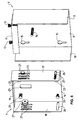
- the first holding part 6 consists of a plate 8, which is formed for example of a metallic sheet metal part.
- This plate 8 is provided with lateral bends 9 and 10.
- the upper portion of the plate 8 is provided with a further bend 11, which is provided with two threaded holes, in which two screws 12 and 13 are screwed.
- a threaded shaft 14 is fixed, which is arranged perpendicular to the plate 8.
- openings 15 are further provided with which this first holding part 6 in a known manner on the flat screen 1 (FIG. Fig. 3 and 4 ) can be attached.
- the second holding part 7 is also formed from a plate 16, which is also provided with lateral bends 17 and 18, which form two laterally extending webs.
- This plate 16 is preferably made of a metallic sheet metal part.
- This plate 16 is also angled and forms a support surface 19th
- the plate 16 is provided with four threaded holes, in each of which a screw 20, 21, 22 and 23 can be screwed.
- a slot-shaped opening 24 is embedded, which has a width which corresponds to at least 1.5 times the diameter of the shaft 14.
- upper recesses 25 and lower recesses 26 are mounted in the lateral extending webs 17 and 18 .
- the upper recesses 25 are formed as longitudinally extending slots, while the lower recesses 26 are formed as transverse slots.
- 17 and 18 are arranged several parallel longitudinal slots per web.
- screws 27 can be used, with which this second holding part 7 on the stator 3 (FIGS. Fig. 3 and 4 ) can be attached.
- the second holding part 7 is connected via the screws 27 to the stator 3.
- the stand 3 is provided with rows of holes 28, the holes 29 correspond to the longitudinal slots 25 and the transverse slots 26.
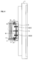
- the shaft 14 projects through the slot-shaped opening 24, which is arranged in the plate 16 of the second holding part.
- the plate 8 of the first holding part 6 is supported on the screws 20, 21, 22 and 23, which are screwed into the plate 16 of the second holding part. Furthermore, the first holding part 6 is supported on the support surface 19 of the second holding part 7 via the screws 12 and 13.
- the first holding part 6 can be exactly adjusted with respect to the second holding part 7, which means that the flat screen 1 with respect to the Stand 3 or the adjacent flat screens can be accurately aligned.
- the screws 12 and 13 the lateral inclination of the flat screen can be adjusted.
- the screws 20 to 23 on the one hand, the distance of the first holding part 6 with respect to the second holding part 7 can be adjusted, in addition, can be adjusted by these screws 20 to 23 each angular position.
- a threaded nut 30 is screwed onto the shaft 14, which projects through the slot-shaped opening 24 of the plate 16.
- the screws 27 and the threaded nut 30 may be provided with caps, by which a tightening or loosening of these screws can be done by hand.
- the screws 12 and 13 or 20 to 23 could also be equipped with caps, but advantageously they are operated with a wrench.
- the stand 3 for receiving the previously described holding devices 5 of two identical plates 31 and 32, which are fixed parallel to each other and spaced from each other firmly.
- a base plate 33 is provided, with which the two plates 31 and 32 are connected together in the base region, and which can be provided with a foot 34.
- the one longitudinal edge 35 of the plates 31 and 32 is inclined with respect to the base plate 33, while the other longitudinal edge 36 of the plates 31 and 32 with respect to the base plate 33 is perpendicular.
- a bolt 37 can be screwed in the top hole.
- a hook-shaped suspension device 38 a cover 39 can be mounted, with which cover 39, the open side of the stand 3, the mounted on the stand 3 flat screens 1 is opposite, can be covered.
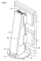
- magnets 40 (FIG. Fig. 7 ) are screwed, which thus hold the lower part of the cover 39, which is formed from a ferromagnetic metal plate, on the stand.
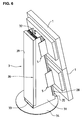
- the mounting device 5 can be attached to the inclined longitudinal edge 35 of the stator 3, as shown in FIG Fig. 6 However, they can also be mounted on the vertical longitudinal edge 36 of the stand 3, shown in FIG Fig. 7 ,
- the flat screens When the flat screens are attached to the inclined longitudinal edge of the stand 3, as shown in FIG Fig. 6 If the flat screens are arranged side by side, the flat screens may be straight, with the upper and lower flat screens being mutually inclined as shown in FIG Fig. 2 is shown.
- the flat screens 1 When the flat screens 1 are arranged on the vertical longitudinal edge 36 of the stand 3, as shown in FIG Fig. 7 is shown, with several juxtaposed stands 3, the flat screens are aligned vertically, but they can be placed in an arc around the command desk, as in Fig. 1 is shown.
- the stands 3 in the previously described embodiment are designed for the reception of two flat screens.
- these stands may have other longitudinal dimensions, which could accommodate more or less than two flat panel displays with the corresponding fixtures.
Landscapes
- Engineering & Computer Science (AREA)
- General Engineering & Computer Science (AREA)
- Mechanical Engineering (AREA)
- Devices For Indicating Variable Information By Combining Individual Elements (AREA)
- Fittings On The Vehicle Exterior For Carrying Loads, And Devices For Holding Or Mounting Articles (AREA)
Abstract
Description
Die vorliegende Erfindung bezieht sich auf einen Ständer mit Halterungsvorrichtung für einen Flachbildschirm, welche Halterungsvorrichtung einen ersten Halteteil, der am Flachbildschirm befestigbar ist, und einen zweiten Halteteil, der am Ständer befestigbar ist, umfasst, wobei der erste Halteteil und der zweite Halteteil über Verbindungsmittel miteinander verbindbar sind, welche Verbindungsmittel so ausgestaltet sind, dass der erste Halteteil bezüglich des zweiten Halteteils einstellbar und ausrichtbar ist, und der erste Halteteil und der zweite Halteteil jeweils aus einer Platte gebildet sind, und an einer der Platten mindestens drei bolzenartige Elemente im wesentlichen senkrecht dazu angebracht sind und in achsialer Richtung bezüglich dieser Platte einstellbar sind, auf welchen bolzenartigen Elementen die andere Platte abstützbar ist, und an der Platte des zweiten Halteteils eine im wesentlichen senkrecht dazu stehende Abstützfläche angebracht ist, auf welcher zwei im wesentlichen parallel zueinander und zur Platte des ersten Halteteils ausgerichtete, an Aufnahmeelementen der Platte des ersten Halteteils angebrachte weitere bolzenartige Elemente abstützbar sind, welche in achsialer Richtung einstellbar sind.The present invention relates to a stand with a mounting device for a flat screen, which mounting device comprises a first holding part, which is attachable to the flat screen, and a second holding part, which is attachable to the stand, wherein the first holding part and the second holding part via connecting means with each other are connectable, which connecting means are designed so that the first holding part is adjustable and alignable with respect to the second holding part, and the first holding part and the second holding part are each formed of a plate, and on one of the plates at least three bolt-like elements substantially perpendicular thereto are mounted and are adjustable in the axial direction with respect to this plate on which bolt-like elements, the other plate is supported, and on the plate of the second holding member is mounted a substantially perpendicular thereto supporting surface, on which two in wese ntlichen parallel to each other and to the plate of the first holding part aligned, mounted on receiving elements of the plate of the first holding part further bolt-like elements are supported, which are adjustable in the axial direction.
Es ist bekannt, dass Steuerpulte oder Kommandopulte mit mehreren Flachbildschirmen ausgestattet werden, auf welchen die gewünschten und erforderlichen Angaben und Informationen ersichtlich sind. Hierbei sind diese Flachbildschirme sowohl über- als auch nebeneinander angeordnet. Diese Flachbildschirme weisen einen sehr schmalen Rand auf, der gegenseitige Abstand voneinander sollte praktisch null sein.It is known that control panels or command panels are equipped with multiple flat screens, on which the desired and required information and information can be seen. Here, these flat screens are arranged both above and next to each other. These flat screens have a very narrow edge, the mutual distance should be virtually zero.
Diese Flachbildschirme sind mittels Halterungsvorrichtungen an Ständern angebracht. Die Halterungsvorrichtungen müssen somit einstellbar sein, damit die Flachbildschirme aufeinander ausgerichtet werden können, da auch geringfügig Versetzungen der Flachbildschirme gegeneinander von blossem Auge sehr gut erkennbar sind und als störend empfunden werden.These flat screens are attached to stands by means of fixtures. The support devices must therefore be adjustable so that the flat screens can be aligned with each other, as even slight displacements of the flat screens against each other are very easily visible to the naked eye and are distracting.
Derartige Halterungsvorrichtungen sind bekannt. So zeigt beispielsweise die
Ferner zeigt die
Die Aufgabe der vorliegenden Erfindung besteht nun darin, einen Ständer mit Halterungsvorrichtung für einen Flachbildschirm zu gestalten, durch welche ein genaues Einjustieren des Flachbildschirms in alle Richtungen ermöglich, der einfach in der Bedienung ist, der günstig hergestellt werden kann und der einfach ausgestaltet ist.The object of the present invention is to design a stand with a mounting device for a flat screen, by which allows an accurate Einjustieren the flat screen in all directions, which is easy to use, which can be manufactured inexpensively and is simple.
Erfindungsgemäss erfolgt die Lösung dieser Aufgabe dadurch, dass die Verbindungsmittel aus einem mit Gewinde versehenem Schaft, welcher an der Platte des ersten Halteteils befestigt ist und durch eine Öffnung in der Platte des zweiten Halteteils hindurch ragt, und einer auf den Schaft aufschraubbaren Gewindemutter bestehen, mit welcher der erste Halteteil gegen den zweiten Halteteil spannbar ist.According to the invention, the solution of this object is achieved in that the connecting means of a threaded shaft, which is fixed to the plate of the first holding part and protrudes through an opening in the plate of the second holding part, and a threaded onto the shaft threaded nut, with which is the first holding part against the second holding part tensioned.
Durch das achsiale Verstellen der bolzenartigen Elemente kann die Distanz zwischen der einen Platte und der anderen Platte eingestellt werden, die erforderlichen Neigungen zwischen diesen beiden Platten lässt sich ebenfalls durch die bolzenartigen Elemente einstellen. Durch die weiteren bolzenartigen Elemente, die an Aufnahmeelementen der Platte des ersten Halteteils angebracht sind, und die sich auf einer Abstützfläche abstützen, die an der Platte des zweiten Halteteils angebracht sind, lässt sich die Höhe der einen Platte zur anderen Platte einjustieren. Zudem kann auch eine eventuelle Schrägstellung eines Flachbildschirms damit ausgeglichen bzw. eingestellt werden.By the axial adjustment of the bolt-like elements, the distance between the one plate and the other plate can be adjusted, the required inclinations between these two plates can also be adjusted by the bolt-like elements. By the other bolt-like elements which are attached to receiving elements of the plate of the first holding part, and which are supported on a support surface which are attached to the plate of the second holding part, the height of a plate can be adjusted to the other plate. In addition, a possible inclination of a flat screen can be compensated or adjusted.
Die Verbindungsmittel bestehen aus einem mit Gewinde versehenem Schaft, welcher an der Platte des ersten Halteteils befestigt ist und durch eine Öffnung in der Platte des zweiten Halteteils hindurchragt, und einer auf den Schaft aufschraubbaren Gewindemutter, mit welcher der erste Halteteil gegen den zweiten Halteteil spannbar ist. Dadurch kann erreicht werden, dass nach dem Einstellen des ersten Halteteils bezüglich des zweiten Halteteils über die bolzenartigen Elemente durch Festziehen dieser einen Gewindemutter die beiden Halteteile in der eingestellten Position fixiert sind.The connecting means consist of a threaded shaft which is fixed to the plate of the first holding part and protrudes through an opening in the plate of the second holding part, and a screwed onto the shaft threaded nut, with which the first holding part is clamped against the second holding part. It can thereby be achieved that after adjusting the first holding part with respect to the second holding part via the bolt-like elements by tightening this a threaded nut, the two holding parts are fixed in the set position.
Indem die Öffnung der Platte des zweiten Halteteils schlitzförmig ausgebildet ist und eine Breite hat, die mindestens dem 1,5-fachen des Durchmesser des Schaftes entspricht, können die erforderlichen Verstellungen des ersten Halteteils bezüglich des zweiten Halteteils in einem bestimmten Ausmass problemlos ausgeführt werden.By the opening of the plate of the second holding part is slit-shaped and has a width which is at least 1.5 times the diameter of the shaft, the required adjustments of the first holding part with respect to the second holding part can be carried out to a certain extent easily.
In vorteilhafter Weise bestehen die bolzenartigen Elemente und die weiteren bolzenartigen Elemente, welche in jeweilige Gewindelöcher einschraubbar sind, die an der Platte des zweiten Halteteils bzw. an den Aufnahmeelementen der Platte des ersten Halteteils angebracht sind, aus Schrauben, wodurch sich ein sehr einfaches Einstellen ergibt, und wodurch auch die Herstellung in günstiger Weise erfolgen kann.Advantageously, the bolt-like elements and the other bolt-like elements, which are screwed into respective threaded holes which are mounted on the plate of the second holding part or on the receiving elements of the plate of the first holding part, from screws, resulting in a very simple setting , and whereby the production can be carried out in a favorable manner.
Eine weitere vorteilhafte Ausgestaltung der Erfindung besteht darin, dass der erste Halteteil und der zweite Halteteil aus jeweils einem metallischen Blechteil gebildet sind, und dass die Aufnahmeelemente des ersten Halteteils durch eine Abwinkelung des entsprechenden Blechteils und die Abstützfläche des zweiten Halteteils durch eine Abwinkelung des entsprechenden Blechteils gebildet sind. Dies ergibt eine besonders einfache Herstellung der beiden Halteteile.A further advantageous embodiment of the invention is that the first holding part and the second holding part are each formed of a metallic sheet metal part, and that the receiving elements of the first holding part by a bend of the corresponding sheet metal part and the support surface of the second holding part by a bend of the corresponding sheet metal part are formed. This results in a particularly simple production of the two holding parts.
Eine weitere vorteilhafte Ausgestaltung der Erfindung besteht darin, dass der Ständer aus zwei gleichen Platten gebildet ist, welche parallel zueinander und voneinander beabstandet miteinander fest verbunden sind und eine Grundplatte aufweisen, dass der eine längsseitige Rand der Platten bezüglich der Grundplatte geneigt ist, während der andere längsseitige Rand der Platten bezüglich der Grundplatte senkrecht verläuft, und dass entlang der längsseitigen Ränder der Platten Lochreihen angebracht sind.A further advantageous embodiment of the invention is that the stand is formed of two identical plates, which are fixed parallel to each other and spaced from each other firmly and have a base plate, that is inclined one longitudinal edge of the plates with respect to the base plate, while the other longitudinal edge of the plates with respect to the base plate is perpendicular, and that along the longitudinal edges of the plates rows of holes are mounted.
Durch diese Ausgestaltung der Ständer können die Haltevorrichtungen in einfacher Weise und in der Höhe wählbar auf beiden Seiten des Ständers angebracht werden, auf der einen Seite sind die durch die Halterungsvorrichtungen getragenen Flachbildschirme bezüglich der Bedienerperson geneigt, während auf der anderen Seite die Flachbildschirme im Bogen um die Bedienerperson angeordnet werden können.This configuration of the stand, the holding devices in a simple manner and in height selectable on both sides of the stand be mounted on one side, the flat screens supported by the support devices are inclined with respect to the operator, while on the other side, the flat screens can be arranged in an arc around the operator.
Eine sehr einfache und in der Herstellung günstige Befestigungsart der Halterungsvorrichtung am jeweiligen Ständer ergibt sich dadurch, dass der zweite Halteteil mit zwei jeweils seitlich verlaufenden Stegen ausgestattet ist, in welchen Ausnehmungen angebracht sind, so dass der zweite Halteteil mit dem Ständer über die Löcher der Lochreihen in wählbarer Höhe verschraubbar ist.A very simple and inexpensive to manufacture mounting the mounting device on each stand results from the fact that the second holding part is equipped with two laterally extending webs, in which recesses are mounted, so that the second holding part with the stand on the holes of the rows of holes screwed in selectable height.
In vorteilhafter Weise sind die oberen Ausnehmungen in den Stegen des zweiten Halteteils als längsverlaufende Schlitze ausgebildet und die unteren Ausnehmungen in den Stegen des zweiten Halteteils als querverlaufende Schlitze ausgebildet. Dadurch können bereits grobe Voreinstellungen vorgenommen werden, die Löcher der Lochreihen sind immer passend auf diese Ausnehmungen.Advantageously, the upper recesses in the webs of the second holding part are formed as longitudinal slots and the lower recesses formed in the webs of the second holding part as transverse slots. As a result, already rough presettings can be made, the holes of the rows of holes are always suitable for these recesses.
In vorteilhafter Weise ist an der den am Ständer angebrachten Halterungsvorrichtungen gegenüberliegenden Seite des Ständers eine Abdeckung anbringbar, welche am oberen Endbereich mit einer Einhängevorrichtung ausgebildet ist, welche im Bolzen einhängbar ist, die am oberen Ende des Ständers in Löcher der Lochreihen einsetzbar und befestigbar sind. Dadurch lässt sich diese Abdeckung sehr einfach am Ständer anbringen, diese ist an beiden Seiten des Ständers einsetzbar, indem die Bolzen jeweils in die entsprechenden Löcher der Lochreihen befestigt werden.Advantageously, a cover is attached to the opposite side of the stator attached to the support devices, which is formed at the upper end with a suspension device which can be suspended in the bolt, which can be inserted and fastened at the upper end of the stator in holes of the rows of holes. This makes it very easy to attach this cover to the stand, this can be used on both sides of the stand by the bolts are respectively mounted in the corresponding holes of the rows of holes.
In vorteilhafter Weise besteht die Abdeckung aus einem ferromagnetischen Blechelement, so dass dieses im unteren Bereich des Ständers durch in die entsprechenden Löcher der Lochreihen eingesetzten Magnete festgehalten werden kann, welche auf der entsprechenden Seite des Ständers angebracht werden können.Advantageously, the cover consists of a ferromagnetic sheet metal element, so that it can be held in the lower region of the stator by magnets inserted into the corresponding holes of the rows of holes, which can be mounted on the corresponding side of the stator.
Eine Ausführungsform der Erfindung wird nachfolgend anhand der beiliegenden Zeichnung beispielhaft näher erläutert.An embodiment of the invention will be explained in more detail by way of example with reference to the accompanying drawings.
Es zeigt
-
Fig. 1 in räumlicher Darstellung die Anordnung von Flachbildschirmen eines Kommandopultes, wobei die Flachbildschirme zum Kommandopult bogenförmig angeordnet sind; -
Fig. 2 in räumlicher Darstellung die Anordnung von Flachbi Idschirmen eines Kommandopultes, wobei die Flachbildschirme geneigt angeordnet sind; -
Fig. 3 eine Darstellung im Schnitt einer Halterungsvorrichtung, befestigt im Ständer und mit aufgesetztem Flachbildschirm; -
Fig. 4 eine Ansicht von oben auf die Halterungsvorrichtung gemässFig. 3 , zum Teil im Schnitt; -
Fig. 5 in räumlicher und separater Darstellung den ersten Halteteil und den zweiten Halteteil, welche die Halterungsvorrichtung bilden; -
Fig. 6 in räumlicher Darstellung die Anordnung von zwei Halterungsvorrichtungen mit darauf aufgesetzten Flachbildschirmen am Ständer auf dessen geneigter Seite; und -
Fig. 7 in räumlicher Darstellung die Anordnung von zwei Halterungsvorrichtungen mit darauf aufgesetzten Flachbildschirmen am Ständer auf dessen senkrechter Seite.
-
Fig. 1 in spatial representation, the arrangement of flat screens of a Kommandopultes, the flat screens are arranged arcuate to Kommandopult; -
Fig. 2 in spatial representation, the arrangement of Flachbi Idschirmen a Kommandopultes, the flat screens are arranged inclined; -
Fig. 3 an illustration in section of a mounting device mounted in the stand and with attached flat screen; -
Fig. 4 a view from above of the mounting device accordingFig. 3 , partly in section; -
Fig. 5 in spatial and separate representation of the first holding part and the second holding part, which form the holding device; -
Fig. 6 in a spatial representation, the arrangement of two mounting devices with it placed flat screens on the stand on the inclined side; and -
Fig. 7 in a spatial representation, the arrangement of two mounting devices with it placed flat screens on the stand on the vertical side.
Wie aus
Die Flachbildschirme 1 weisen einen sehr schmalen Rand auf, zwischen den einzelnen Flachbildschirmen 1 sollte bei den vorgängig beschriebenen Anordnungen möglichst kein Spalt bestehen, die Flachbildschirme sollten auch gegenseitig genau ausgerichtet sein, damit diese nicht gegeneinander versetzt sind, was sich für den Betrachter als störend herausstellen würde. Dies kann durch die Halterungsvorrichtungen, wie hier später noch beschrieben wird, vermieden werden.The
Wie aus
Die Halterungsvorrichtung 5, wie sie in den
In einem mittleren Bereich der Platte 8 ist ein mit einem Gewinde versehener Schaft 14 befestigt, der senkrecht zur Platte 8 angeordnet ist. In der Platte 8 sind ferner Öffnungen 15 vorgesehen, mit welchen dieser erste Halteteil 6 in bekannter Weise am Flachbildschirm 1 (
Der zweite Halteteil 7 ist ebenfalls aus einer Platte 16 gebildet, die ebenfalls mit seitlichen Abwinkelungen 17 und 18 ausgestattet ist, welche zwei seitlich verlaufende Stege bilden. Auch diese Platte 16 besteht vorzugsweise aus einem metallischen Blechteil.The
Der obere Randbereich dieser Platte 16 ist ebenfalls abgewinkelt und bildet eine Abstützfläche 19.The upper edge region of this
Die Platte 16 ist mit vier Gewindelöchern versehen, in welche jeweils eine Schraube 20, 21, 22 bzw. 23 einschraubbar ist. Im mittleren Bereich der Platte 16 ist eine schlitzförmige Öffnung 24 eingelassen, die eine Breite hat, die mindestens dem 1,5-fachen des Durchmessers des Schaftes 14 entspricht.The
In den seitlichen verlaufenden Stegen 17 und 18 sind obere Ausnehmungen 25 und untere Ausnehmungen 26 angebracht. Die oberen Ausnehmungen 25 sind als längs verlaufende Schlitze ausgebildet, während die unteren Ausnehmungen 26 als quer verlaufende Schlitze ausgebildet sind. Im vorliegenden Ausführungsbeispiel sind pro Steg 17 bzw. 18 mehrere parallel verlaufende Längsschlitze angeordnet. In diese längs verlaufenden Schlitze 25 bzw. quer verlaufenden Schlitze 26 können Schrauben 27 eingesetzt werden, mit welchen dieser zweite Halteteil 7 am Ständer 3 (
Wie aus den
Auf den zweiten Halteteil 7 aufgesetzt wird der erste Halteteil 6. Hierbei ragt der Schaft 14 durch die schlitzförmige Öffnung 24, die in der Platte 16 des zweiten Halteteils angeordnet ist. Die Platte 8 des ersten Halteteils 6 stützt sich auf den Schrauben 20, 21, 22 und 23 ab, die in der Platte 16 des zweiten Halteteils eingeschraubt sind. Ferner stützt sich der erste Halteteil 6 über die Schrauben 12 und 13 auf der Abstützfläche 19 des zweiten Halteteils 7 ab.In this case, the
Der erste Halteteil 6 lässt sich bezüglich des zweiten Halteteils 7 genau einjustieren, was bedeutet, dass der Flachbildschirm 1 bezüglich des Ständers 3 bzw. der benachbarten Flachbildschirme genau ausgerichtet werden kann. Durch Verstellen der Schrauben 12 und 13 kann die Seitenneigung des Flachbildschirms eingestellt werden. Durch Einstellen der Schrauben 20 bis 23 lässt sich einerseits der Abstand des ersten Halteteils 6 bezüglich des zweiten Halteteils 7 einstellen, zusätzlich lässt sich durch diese Schrauben 20 bis 23 jede Winkellage einstellen.The first holding part 6 can be exactly adjusted with respect to the
Wenn die Einstellung beendet ist, wird auf den Schaft 14, der durch die schlitzförmige Öffnung 24 der Platte 16 hindurchragt, eine Gewindemutter 30 aufgeschraubt. Mit dieser Gewindemutter 30 lässt sich der erste Halteteil 6 gegenüber dem zweiten Halteteil 7 verspannen, die vorgenommenen Einstellungen werden dadurch fixiert. Die Schrauben 27 und die Gewindemutter 30 können mit Kappen versehen sein, durch welche ein Anziehen bzw. Lösen dieser Schrauben von Hand erfolgen kann. Die Schrauben 12 und 13 bzw. 20 bis 23 könnten ebenfalls mit Kappen ausgestattet sein, in vorteilhafter Weise werden diese aber mit einem Schraubenschlüssel betätigt.When the adjustment is completed, a threaded
Wie aus den
Im jeweils obersten Loch der Lochreihen 28, welche den im Ständer 3 angebrachten Flachbildschirme 1 gegenüberliegend sind, kann im obersten Loch jeweils ein Bolzen 37 eingeschraubt werden. In diese Bolzen 37, wie dies aus
Wie aus den
Wenn die Flachbildschirme am geneigten längsseitigen Rand des Ständers 3 befestigt sind, wie dies in
Die Ständer 3 im vorgängig beschriebenen Ausführungsbeispiel sind ausgelegt für die Aufnahme von zwei Flachbildschirmen. Selbstverständlich können diese Ständer andere Längsabmessungen haben, wodurch mehr oder auch weniger als zwei Flachbildschirme mit den entsprechenden Halterungsvorrichtungen aufgenommen werden könnten.The stands 3 in the previously described embodiment are designed for the reception of two flat screens. Of course, these stands may have other longitudinal dimensions, which could accommodate more or less than two flat panel displays with the corresponding fixtures.
Mit diesen Halterungsvorrichtungen für Flachbildschirme und den dazugehörenden Ständern wird ein sehr einfaches System erreicht, an welchem die Flachbildschirme befestigt werden können, wobei die Flachbildschirme in einfacher Weise und genau gegenseitig ausgerichtet werden können. Dieses System ist sehr einfach in der Handhabung und kostengünstig in der Herstellung. Es kann sehr flexibel eingesetzt werden.These flat panel mounting brackets and associated stands achieve a very simple system to which the flat panel displays can be attached, with the flat screens being easily and accurately aligned with each other. This system is very easy to handle and inexpensive to manufacture. It can be used very flexibly.
Claims (11)
- Stand with fixture for a flat screen monitor (1), which fixture comprises a first mounting part (6), which is attachable to the flat screen monitor (1), and a second mounting part (7), which is attachable to the stand (3), the first mounting part (6) and the second mounting part (7) being connectible to each other via connecting means (14, 30), which connecting means (14, 30) are designed such that the first mounting part (6) is adjustable and alignable with respect to the second mounting part (7), and the first mounting part (6) and the second mounting part (7) are each formed by a plate (8, 16), and at least three bolt elements (20, 21, 22) are installed on one of the plates (8) substantially at a right angle thereto and are adjustable in axial direction with respect to this plate (8), on which bolt elements (20, 21, 22) the other plate (16) is supportable, and installed on the plate (16) of the second mounting part (7) is a support surface (19) situated substantially at a right angle thereto, on which two further bolt elements (12, 13), aligned substantially parallel to one another and to the plate (8) of the first mounting part (6), and installed on receiving elements (11) of the plate (8) of the first mounting part (6), are supportable, which are adjustable in axial direction, characterised in that the connecting means consist of a shaft (14), provided with a threading, which shaft is attached to the plate (8) of the first mounting part (6) and projects through an opening (24) in the plate (16) of the second mounting part (7), and a nut (30) screwable onto the shaft (14), with which nut the first mounting part (6) is able to be tensioned against the second mounting part (7).
- Stand with fixture for a flat screen monitor according to claim 1, characterised in that the opening (24) in the plate (16) of the second mounting part (7) is designed slot-shaped, and has a width corresponding to at least 1.5 times the diameter of the shaft (14).
- Stand with fixture for a flat screen monitor according to claim 1 or 2, characterised in that the bolt elements (20, 21, 22) consist of screws, which are screwable into respective threaded holes provided on the plate (16) of the second mounting part (7).
- Stand with fixture for a flat screen monitor according to one of the claims 1 to 3, characterised in that the further bolt elements (12, 13) consist of screws which are screwable into respective threaded holes provided on the receiving elements (11) of the plate (8) of the first mounting part (6).
- Stand with fixture according to one of the claims 1 to 4, characterised in that the first mounting part (6) and the second mounting part (7) are each made up of a metallic sheet metal part, and in that the receiving elements (11) of the first mounting part (6) are formed by a bending of the respective sheet metal part, and the support surface (19) of the second mounting part (7) by a bending of the respective sheet metal part.
- Stand with fixture according to one of the claims 1 to 5, characterised in that this is formed by two equal plates (31, 32) which are firmly connected to each other in a way parallel to each other and spaced apart from each other, and have a base plate (33), in that the one lengthwise edge (35) of the plates (31, 32) is inclined with respect to the base plate (33) while the other lengthwise edge (36) of the plates (31, 32) runs at a right angle with respect to the base plate (33), and in that rows of holes (28) are provided along the lengthwise edges (35, 36) of the plates (31, 32).
- Stand with fixture according to claim 6, characterised in that the second mounting part (7) is provided with two crosspieces (17, 18) each running laterally, in which recesses (25, 26) are made, so that the second mounting part (7) is screwable to the stand (3) at a selectable height via the holes (29) of the rows of holes (28).
- Stand with fixture according to claim 7, characterised in that the upper recesses in the crosspieces (17, 18) of the second mounting part (7) are designed as longitudinally running slots (25), and the lower recesses in the crosspieces (17, 18) of the second mounting part (7) as transversely running slots (26).
- Stand with fixture according to one of the claims 6 to 8, characterised in that installable on the side of the stand (3) opposite the fixtures (5) provided on the stand (3) is a cover (39), which is designed with a suspension device (38) on the upper end region, which suspension device is able to be hung on bolts (37), that are insertable and fixable in holes (29) of the rows of holes (28) at the upper end of the stand (3).
- Stand with fixture according to claim 9, characterised in that the cover (39) consists of a ferromagnetic sheet metal element, and in that magnets (40) are insertable and fixable in the corresponding holes (29) of the rows of holes (28) in the lower region of the stand (3), which magnets firmly hold the cover (39).
- Stand with fixture according to claim 10, characterised in that the bolts (37) and the magnets (40) are each installable in the corresponding holes (29) of the rows of holes (28), alternatively on the inclined side or on the perpendicular side, and the cover (39) is insertable on both sides of the stand (3).
Priority Applications (3)
| Application Number | Priority Date | Filing Date | Title |
|---|---|---|---|
| AT04101382T ATE413562T1 (en) | 2004-04-02 | 2004-04-02 | STAND WITH HOLDER FOR A FLAT SCREEN |
| EP04101382A EP1582802B1 (en) | 2004-04-02 | 2004-04-02 | Stand with fixture for a flat screen |
| DE502004008403T DE502004008403D1 (en) | 2004-04-02 | 2004-04-02 | Stand with mounting device for a flat screen |
Applications Claiming Priority (1)
| Application Number | Priority Date | Filing Date | Title |
|---|---|---|---|
| EP04101382A EP1582802B1 (en) | 2004-04-02 | 2004-04-02 | Stand with fixture for a flat screen |
Publications (2)
| Publication Number | Publication Date |
|---|---|
| EP1582802A1 EP1582802A1 (en) | 2005-10-05 |
| EP1582802B1 true EP1582802B1 (en) | 2008-11-05 |
Family
ID=34878309
Family Applications (1)
| Application Number | Title | Priority Date | Filing Date |
|---|---|---|---|
| EP04101382A Expired - Lifetime EP1582802B1 (en) | 2004-04-02 | 2004-04-02 | Stand with fixture for a flat screen |
Country Status (3)
| Country | Link |
|---|---|
| EP (1) | EP1582802B1 (en) |
| AT (1) | ATE413562T1 (en) |
| DE (1) | DE502004008403D1 (en) |
Families Citing this family (5)
| Publication number | Priority date | Publication date | Assignee | Title |
|---|---|---|---|---|
| NL2002281C2 (en) * | 2008-12-03 | 2010-06-07 | Vanderkuy Business Dev | MOUNTING AND PRESENTATION SYSTEM FOR MONITORS WITH MEDIA PLAYERS. |
| EP2228583A1 (en) | 2009-03-13 | 2010-09-15 | Giga-Byte Technology Co., Ltd. | Multifunctional support |
| CN101871551B (en) * | 2009-04-21 | 2012-06-27 | 建碁股份有限公司 | Display hanger device |
| CN102635770B (en) * | 2009-04-21 | 2015-06-03 | 建碁股份有限公司 | Display hanger device |
| FR3090800B1 (en) | 2018-12-20 | 2022-01-21 | Axeos | Support for audiovisual equipment |
Family Cites Families (5)
| Publication number | Priority date | Publication date | Assignee | Title |
|---|---|---|---|---|
| JP3872590B2 (en) * | 1998-02-27 | 2007-01-24 | 三菱電機株式会社 | Projection-type image display device |
| US6343006B1 (en) | 1998-11-20 | 2002-01-29 | Jerry Moscovitch | Computer display screen system and adjustable screen mount, and swinging screens therefor |
| TW551768U (en) * | 2002-01-18 | 2003-09-01 | Coretronic Corp | Multi-axis adjustment device |
| DE10205869B4 (en) * | 2002-02-13 | 2010-04-15 | Mavig Gmbh | Carrier for carrying at least one display device |
| EP1496776A4 (en) * | 2002-04-24 | 2006-08-02 | Innovative Office Products Inc | Multiple electronic device reorienting support |
-
2004
- 2004-04-02 EP EP04101382A patent/EP1582802B1/en not_active Expired - Lifetime
- 2004-04-02 AT AT04101382T patent/ATE413562T1/en active
- 2004-04-02 DE DE502004008403T patent/DE502004008403D1/en not_active Expired - Lifetime
Also Published As
| Publication number | Publication date |
|---|---|
| DE502004008403D1 (en) | 2008-12-18 |
| ATE413562T1 (en) | 2008-11-15 |
| EP1582802A1 (en) | 2005-10-05 |
Similar Documents
| Publication | Publication Date | Title |
|---|---|---|
| DE102013112645B3 (en) | hinge | |
| DE102011017467B3 (en) | Support arrangement for solar modules | |
| EP2604381A1 (en) | Modular holding system for fixing pieces | |
| EP1312852A2 (en) | Device for forming a support wall for flat panel displays | |
| DE102004005884A1 (en) | joining device | |
| EP1977124A1 (en) | Device for holding and positioning implements, workpieces and tools | |
| EP1582802B1 (en) | Stand with fixture for a flat screen | |
| DE10318276B4 (en) | Mounted on a substructure bracket for plates | |
| DE202009004012U1 (en) | component support | |
| EP3034751B1 (en) | Mounting plate | |
| EP1624198A2 (en) | Connection fitting for panels, specially for shelve boards | |
| DE4011109A1 (en) | ADJUSTABLE PLOW | |
| WO2023088627A1 (en) | Fastening element and system | |
| EP0413396B1 (en) | Domestic appliance, especially diswashing machine | |
| DE9301520U1 (en) | Device for fastening installation elements | |
| DE3941613A1 (en) | Adjustable fixing system for electrical distribution appts. - has slider clamped in required position along support rail via associated threaded screw | |
| EP1630312B1 (en) | Wall connector | |
| DE102019133682B4 (en) | Towel holder | |
| DE102019125091B4 (en) | support for at least one monitor | |
| DE3150630A1 (en) | Supporting bracket | |
| EP1791679B1 (en) | Kit for assembling a modular bracket | |
| CH663564A5 (en) | MANUFACTURING DEVICE. | |
| DE29904778U1 (en) | Modular clamping system | |
| EP4091501A1 (en) | Holding device for attaching an accessory to a frame element of a table, table and method for attaching the accessory | |
| DE2253347C3 (en) | Device for fastening runways |
Legal Events
| Date | Code | Title | Description |
|---|---|---|---|
| PUAI | Public reference made under article 153(3) epc to a published international application that has entered the european phase |
Free format text: ORIGINAL CODE: 0009012 |
|
| AK | Designated contracting states |
Kind code of ref document: A1 Designated state(s): AT BE BG CH CY CZ DE DK EE ES FI FR GB GR HU IE IT LI LU MC NL PL PT RO SE SI SK TR |
|
| AX | Request for extension of the european patent |
Extension state: AL HR LT LV MK |
|
| 17P | Request for examination filed |
Effective date: 20060318 |
|
| AKX | Designation fees paid |
Designated state(s): AT BE BG CH CY CZ DE DK EE ES FI FR GB GR HU IE IT LI LU MC NL PL PT RO SE SI SK TR |
|
| RTI1 | Title (correction) |
Free format text: STAND WITH FIXTURE FOR A FLAT SCREEN |
|
| GRAP | Despatch of communication of intention to grant a patent |
Free format text: ORIGINAL CODE: EPIDOSNIGR1 |
|
| GRAS | Grant fee paid |
Free format text: ORIGINAL CODE: EPIDOSNIGR3 |
|
| GRAA | (expected) grant |
Free format text: ORIGINAL CODE: 0009210 |
|
| AK | Designated contracting states |
Kind code of ref document: B1 Designated state(s): AT BE BG CH CY CZ DE DK EE ES FI FR GB GR HU IE IT LI LU MC NL PL PT RO SE SI SK TR |
|
| REG | Reference to a national code |
Ref country code: GB Ref legal event code: FG4D Free format text: NOT ENGLISH |
|
| REG | Reference to a national code |
Ref country code: CH Ref legal event code: EP |
|
| REG | Reference to a national code |
Ref country code: IE Ref legal event code: FG4D Free format text: LANGUAGE OF EP DOCUMENT: GERMAN |
|
| REF | Corresponds to: |
Ref document number: 502004008403 Country of ref document: DE Date of ref document: 20081218 Kind code of ref document: P |
|
| REG | Reference to a national code |
Ref country code: CH Ref legal event code: NV Representative=s name: BOVARD AG PATENTANWAELTE |
|
| NLV1 | Nl: lapsed or annulled due to failure to fulfill the requirements of art. 29p and 29m of the patents act | ||
| PG25 | Lapsed in a contracting state [announced via postgrant information from national office to epo] |
Ref country code: ES Free format text: LAPSE BECAUSE OF FAILURE TO SUBMIT A TRANSLATION OF THE DESCRIPTION OR TO PAY THE FEE WITHIN THE PRESCRIBED TIME-LIMIT Effective date: 20090216 |
|
| PG25 | Lapsed in a contracting state [announced via postgrant information from national office to epo] |
Ref country code: FI Free format text: LAPSE BECAUSE OF FAILURE TO SUBMIT A TRANSLATION OF THE DESCRIPTION OR TO PAY THE FEE WITHIN THE PRESCRIBED TIME-LIMIT Effective date: 20081105 Ref country code: PL Free format text: LAPSE BECAUSE OF FAILURE TO SUBMIT A TRANSLATION OF THE DESCRIPTION OR TO PAY THE FEE WITHIN THE PRESCRIBED TIME-LIMIT Effective date: 20081105 Ref country code: NL Free format text: LAPSE BECAUSE OF FAILURE TO SUBMIT A TRANSLATION OF THE DESCRIPTION OR TO PAY THE FEE WITHIN THE PRESCRIBED TIME-LIMIT Effective date: 20081105 Ref country code: SI Free format text: LAPSE BECAUSE OF FAILURE TO SUBMIT A TRANSLATION OF THE DESCRIPTION OR TO PAY THE FEE WITHIN THE PRESCRIBED TIME-LIMIT Effective date: 20081105 |
|
| REG | Reference to a national code |
Ref country code: IE Ref legal event code: FD4D |
|
| PG25 | Lapsed in a contracting state [announced via postgrant information from national office to epo] |
Ref country code: BG Free format text: LAPSE BECAUSE OF FAILURE TO SUBMIT A TRANSLATION OF THE DESCRIPTION OR TO PAY THE FEE WITHIN THE PRESCRIBED TIME-LIMIT Effective date: 20090205 Ref country code: EE Free format text: LAPSE BECAUSE OF FAILURE TO SUBMIT A TRANSLATION OF THE DESCRIPTION OR TO PAY THE FEE WITHIN THE PRESCRIBED TIME-LIMIT Effective date: 20081105 Ref country code: IE Free format text: LAPSE BECAUSE OF FAILURE TO SUBMIT A TRANSLATION OF THE DESCRIPTION OR TO PAY THE FEE WITHIN THE PRESCRIBED TIME-LIMIT Effective date: 20081105 Ref country code: DK Free format text: LAPSE BECAUSE OF FAILURE TO SUBMIT A TRANSLATION OF THE DESCRIPTION OR TO PAY THE FEE WITHIN THE PRESCRIBED TIME-LIMIT Effective date: 20081105 Ref country code: RO Free format text: LAPSE BECAUSE OF FAILURE TO SUBMIT A TRANSLATION OF THE DESCRIPTION OR TO PAY THE FEE WITHIN THE PRESCRIBED TIME-LIMIT Effective date: 20081105 |
|
| PG25 | Lapsed in a contracting state [announced via postgrant information from national office to epo] |
Ref country code: SE Free format text: LAPSE BECAUSE OF FAILURE TO SUBMIT A TRANSLATION OF THE DESCRIPTION OR TO PAY THE FEE WITHIN THE PRESCRIBED TIME-LIMIT Effective date: 20090205 Ref country code: PT Free format text: LAPSE BECAUSE OF FAILURE TO SUBMIT A TRANSLATION OF THE DESCRIPTION OR TO PAY THE FEE WITHIN THE PRESCRIBED TIME-LIMIT Effective date: 20090406 Ref country code: CZ Free format text: LAPSE BECAUSE OF FAILURE TO SUBMIT A TRANSLATION OF THE DESCRIPTION OR TO PAY THE FEE WITHIN THE PRESCRIBED TIME-LIMIT Effective date: 20081105 |
|
| PLBE | No opposition filed within time limit |
Free format text: ORIGINAL CODE: 0009261 |
|
| STAA | Information on the status of an ep patent application or granted ep patent |
Free format text: STATUS: NO OPPOSITION FILED WITHIN TIME LIMIT |
|
| PG25 | Lapsed in a contracting state [announced via postgrant information from national office to epo] |
Ref country code: SK Free format text: LAPSE BECAUSE OF FAILURE TO SUBMIT A TRANSLATION OF THE DESCRIPTION OR TO PAY THE FEE WITHIN THE PRESCRIBED TIME-LIMIT Effective date: 20081105 |
|
| 26N | No opposition filed |
Effective date: 20090806 |
|
| BERE | Be: lapsed |
Owner name: MAURER, ERNST Effective date: 20090430 |
|
| GBPC | Gb: european patent ceased through non-payment of renewal fee |
Effective date: 20090402 |
|
| REG | Reference to a national code |
Ref country code: FR Ref legal event code: ST Effective date: 20091231 |
|
| PG25 | Lapsed in a contracting state [announced via postgrant information from national office to epo] |
Ref country code: FR Free format text: LAPSE BECAUSE OF NON-PAYMENT OF DUE FEES Effective date: 20091222 Ref country code: GB Free format text: LAPSE BECAUSE OF NON-PAYMENT OF DUE FEES Effective date: 20090402 Ref country code: MC Free format text: LAPSE BECAUSE OF NON-PAYMENT OF DUE FEES Effective date: 20090430 |
|
| PG25 | Lapsed in a contracting state [announced via postgrant information from national office to epo] |
Ref country code: BE Free format text: LAPSE BECAUSE OF NON-PAYMENT OF DUE FEES Effective date: 20090430 |
|
| PG25 | Lapsed in a contracting state [announced via postgrant information from national office to epo] |
Ref country code: GR Free format text: LAPSE BECAUSE OF FAILURE TO SUBMIT A TRANSLATION OF THE DESCRIPTION OR TO PAY THE FEE WITHIN THE PRESCRIBED TIME-LIMIT Effective date: 20090206 |
|
| PG25 | Lapsed in a contracting state [announced via postgrant information from national office to epo] |
Ref country code: IT Free format text: LAPSE BECAUSE OF FAILURE TO SUBMIT A TRANSLATION OF THE DESCRIPTION OR TO PAY THE FEE WITHIN THE PRESCRIBED TIME-LIMIT Effective date: 20081105 |
|
| REG | Reference to a national code |
Ref country code: CH Ref legal event code: PFA Owner name: MAURER, ERNST Free format text: MAURER, ERNST#HOEH 97L#3615 HEIMENSCHWAND (CH) -TRANSFER TO- MAURER, ERNST#HOEH 97L#3615 HEIMENSCHWAND (CH) |
|
| PG25 | Lapsed in a contracting state [announced via postgrant information from national office to epo] |
Ref country code: LU Free format text: LAPSE BECAUSE OF NON-PAYMENT OF DUE FEES Effective date: 20090402 |
|
| PG25 | Lapsed in a contracting state [announced via postgrant information from national office to epo] |
Ref country code: HU Free format text: LAPSE BECAUSE OF FAILURE TO SUBMIT A TRANSLATION OF THE DESCRIPTION OR TO PAY THE FEE WITHIN THE PRESCRIBED TIME-LIMIT Effective date: 20090506 |
|
| PG25 | Lapsed in a contracting state [announced via postgrant information from national office to epo] |
Ref country code: TR Free format text: LAPSE BECAUSE OF FAILURE TO SUBMIT A TRANSLATION OF THE DESCRIPTION OR TO PAY THE FEE WITHIN THE PRESCRIBED TIME-LIMIT Effective date: 20081105 |
|
| PG25 | Lapsed in a contracting state [announced via postgrant information from national office to epo] |
Ref country code: CY Free format text: LAPSE BECAUSE OF FAILURE TO SUBMIT A TRANSLATION OF THE DESCRIPTION OR TO PAY THE FEE WITHIN THE PRESCRIBED TIME-LIMIT Effective date: 20081105 |
|
| PGFP | Annual fee paid to national office [announced via postgrant information from national office to epo] |
Ref country code: DE Payment date: 20210427 Year of fee payment: 18 |
|
| PGFP | Annual fee paid to national office [announced via postgrant information from national office to epo] |
Ref country code: AT Payment date: 20210420 Year of fee payment: 18 Ref country code: CH Payment date: 20210413 Year of fee payment: 18 |
|
| REG | Reference to a national code |
Ref country code: DE Ref legal event code: R119 Ref document number: 502004008403 Country of ref document: DE |
|
| REG | Reference to a national code |
Ref country code: CH Ref legal event code: PL |
|
| REG | Reference to a national code |
Ref country code: AT Ref legal event code: MM01 Ref document number: 413562 Country of ref document: AT Kind code of ref document: T Effective date: 20220402 |
|
| PG25 | Lapsed in a contracting state [announced via postgrant information from national office to epo] |
Ref country code: LI Free format text: LAPSE BECAUSE OF NON-PAYMENT OF DUE FEES Effective date: 20220430 Ref country code: DE Free format text: LAPSE BECAUSE OF NON-PAYMENT OF DUE FEES Effective date: 20221103 Ref country code: CH Free format text: LAPSE BECAUSE OF NON-PAYMENT OF DUE FEES Effective date: 20220430 Ref country code: AT Free format text: LAPSE BECAUSE OF NON-PAYMENT OF DUE FEES Effective date: 20220402 |