EP1580508A1 - Material feeding apparatus for rotary hearth furnace - Google Patents
Material feeding apparatus for rotary hearth furnace Download PDFInfo
- Publication number
- EP1580508A1 EP1580508A1 EP03774157A EP03774157A EP1580508A1 EP 1580508 A1 EP1580508 A1 EP 1580508A1 EP 03774157 A EP03774157 A EP 03774157A EP 03774157 A EP03774157 A EP 03774157A EP 1580508 A1 EP1580508 A1 EP 1580508A1
- Authority
- EP
- European Patent Office
- Prior art keywords
- belt conveyor
- flat belt
- raw material
- rotary hearth
- hearth furnace
- Prior art date
- Legal status (The legal status is an assumption and is not a legal conclusion. Google has not performed a legal analysis and makes no representation as to the accuracy of the status listed.)
- Granted
Links
Images




Classifications
-
- F—MECHANICAL ENGINEERING; LIGHTING; HEATING; WEAPONS; BLASTING
- F27—FURNACES; KILNS; OVENS; RETORTS
- F27D—DETAILS OR ACCESSORIES OF FURNACES, KILNS, OVENS OR RETORTS, IN SO FAR AS THEY ARE OF KINDS OCCURRING IN MORE THAN ONE KIND OF FURNACE
- F27D3/00—Charging; Discharging; Manipulation of charge
- F27D3/0033—Charging; Discharging; Manipulation of charge charging of particulate material
-
- F—MECHANICAL ENGINEERING; LIGHTING; HEATING; WEAPONS; BLASTING
- F27—FURNACES; KILNS; OVENS; RETORTS
- F27B—FURNACES, KILNS, OVENS OR RETORTS IN GENERAL; OPEN SINTERING OR LIKE APPARATUS
- F27B3/00—Hearth-type furnaces, e.g. of reverberatory type; Electric arc furnaces ; Tank furnaces
- F27B3/06—Hearth-type furnaces, e.g. of reverberatory type; Electric arc furnaces ; Tank furnaces with movable working chambers or hearths, e.g. tiltable, oscillating or describing a composed movement
-
- F—MECHANICAL ENGINEERING; LIGHTING; HEATING; WEAPONS; BLASTING
- F27—FURNACES; KILNS; OVENS; RETORTS
- F27B—FURNACES, KILNS, OVENS OR RETORTS IN GENERAL; OPEN SINTERING OR LIKE APPARATUS
- F27B3/00—Hearth-type furnaces, e.g. of reverberatory type; Electric arc furnaces ; Tank furnaces
- F27B3/10—Details, accessories or equipment, e.g. dust-collectors, specially adapted for hearth-type furnaces
- F27B3/18—Arrangements of devices for charging
-
- F—MECHANICAL ENGINEERING; LIGHTING; HEATING; WEAPONS; BLASTING
- F27—FURNACES; KILNS; OVENS; RETORTS
- F27B—FURNACES, KILNS, OVENS OR RETORTS IN GENERAL; OPEN SINTERING OR LIKE APPARATUS
- F27B7/00—Rotary-drum furnaces, i.e. horizontal or slightly inclined
- F27B7/20—Details, accessories or equipment specially adapted for rotary-drum furnaces
- F27B7/32—Arrangement of devices for charging
-
- F—MECHANICAL ENGINEERING; LIGHTING; HEATING; WEAPONS; BLASTING
- F27—FURNACES; KILNS; OVENS; RETORTS
- F27D—DETAILS OR ACCESSORIES OF FURNACES, KILNS, OVENS OR RETORTS, IN SO FAR AS THEY ARE OF KINDS OCCURRING IN MORE THAN ONE KIND OF FURNACE
- F27D3/00—Charging; Discharging; Manipulation of charge
- F27D3/0025—Charging or loading melting furnaces with material in the solid state
-
- F—MECHANICAL ENGINEERING; LIGHTING; HEATING; WEAPONS; BLASTING
- F27—FURNACES; KILNS; OVENS; RETORTS
- F27D—DETAILS OR ACCESSORIES OF FURNACES, KILNS, OVENS OR RETORTS, IN SO FAR AS THEY ARE OF KINDS OCCURRING IN MORE THAN ONE KIND OF FURNACE
- F27D3/00—Charging; Discharging; Manipulation of charge
- F27D3/12—Travelling or movable supports or containers for the charge
-
- F—MECHANICAL ENGINEERING; LIGHTING; HEATING; WEAPONS; BLASTING
- F27—FURNACES; KILNS; OVENS; RETORTS
- F27D—DETAILS OR ACCESSORIES OF FURNACES, KILNS, OVENS OR RETORTS, IN SO FAR AS THEY ARE OF KINDS OCCURRING IN MORE THAN ONE KIND OF FURNACE
- F27D3/00—Charging; Discharging; Manipulation of charge
- F27D2003/0034—Means for moving, conveying, transporting the charge in the furnace or in the charging facilities
- F27D2003/0063—Means for moving, conveying, transporting the charge in the furnace or in the charging facilities comprising endless belts
-
- F—MECHANICAL ENGINEERING; LIGHTING; HEATING; WEAPONS; BLASTING
- F27—FURNACES; KILNS; OVENS; RETORTS
- F27D—DETAILS OR ACCESSORIES OF FURNACES, KILNS, OVENS OR RETORTS, IN SO FAR AS THEY ARE OF KINDS OCCURRING IN MORE THAN ONE KIND OF FURNACE
- F27D3/00—Charging; Discharging; Manipulation of charge
- F27D2003/0034—Means for moving, conveying, transporting the charge in the furnace or in the charging facilities
- F27D2003/0066—Means for moving, conveying, transporting the charge in the furnace or in the charging facilities comprising scrapers or systems to pull out
-
- F—MECHANICAL ENGINEERING; LIGHTING; HEATING; WEAPONS; BLASTING
- F27—FURNACES; KILNS; OVENS; RETORTS
- F27D—DETAILS OR ACCESSORIES OF FURNACES, KILNS, OVENS OR RETORTS, IN SO FAR AS THEY ARE OF KINDS OCCURRING IN MORE THAN ONE KIND OF FURNACE
- F27D3/00—Charging; Discharging; Manipulation of charge
- F27D3/12—Travelling or movable supports or containers for the charge
- F27D2003/121—Band, belt or mesh
Definitions
- This invention relates to a pellet-feeding apparatus for a rotary hearth furnace, for feeding raw material to a rotary hearth furnace by using a flat belt conveyor.
- the invention relates to a raw material-feeding apparatus feeding raw materials to a rotary hearth furnace for mainly producing reduced iron by using an iron ore or the wastes of iron making.
- a rotary hearth furnace is a movable hearth furnace for heating and reducing metal oxides such as iron ore or the wastes of iron making, and a rotary hearth furnace, the hearth of which is a horizontal surface and rotates, is known from Japanese Examined Patent Publication (Kokoku) No. 45-19569, and so forth.
- the raw-material processed inside this rotary hearth furnace is, in advance, agglomerated and is charged into the rotary hearth by a charging device provided at an upper part of the furnace. Because an outer peripheral portion of the rotary hearth has a greater area than its inner peripheral portion, however, contrivances are required so as to uniformly disperse the raw materials on the entire surface of the rotary hearth. Therefore, a vibration conveyor and a swivel conveyor have been used in the past for this uniform dispersion charging device.
- Japanese Unexamined Patent Publication (Kokai) No. 11-293317 discloses a mechanism for charging a pellet (hereinafter called "raw material") into a rotary hearth furnace, having the construction in which a plurality of screens for dividedly guiding the pellets is arranged in a trough of a vibration conveyor for charging the pellet to the rotary hearth furnace and uniformly charges the pellets into the rotary hearth furnace by adjusting openings of passages partitioned by these screens.
- Japanese Unexamined Patent Publication (Kokai) No. 11-337265 discloses a mechanism for uniformly charging the pellets into the rotary hearth furnace by adjusting a swivel speed in accordance with a position of a pivot of the swivel conveyor.
- the agglomerated raw material has various properties such as low strength, brittleness, easy adhesion, etc, depending of the condition of the raw material, formation method and water content. Therefore, the conventional method or the method using the vibration conveyor, for example, is not able to satisfy the charging function itself because it invites dusting, deformation and mutual adhesion, by the application of vibration to the agglomerated raw material.
- the swivel conveyor has theoretically only a function of charging the raw material onto the swivel orbit and is a system that cannot uniformly disperse and charge the pellet.
- the invention provides a raw material-feeding apparatus capable of uniformly dispersing, and feeding into a furnace, an agglomerated raw material that is likely to undergo dusting, deformation and mutual adhesion.
- the invention is directed to the following points.
- the invention was completed as a result of intensive studies for solving the problems described above and provides a raw-material-feeding apparatus for a rotary hearth furnace, for feeding a raw material to a rotary hearth furnace capable of uniformly dispersing and feeding a agglomerated raw material that is likely to undergo dusting, deformation and mutual adhesion, into a furnace by obliquely disposing a scraper for guiding the raw-material on the flat belt conveyor to a side surface of the flat belt conveyor with respect to a traveling direction of the flat belt conveyor.
- the gist of the invention is described in the Claims for Patent.
- Fig. 1 shows a raw material-feeding apparatus for a rotary hearth furnace according to an embodiment of the invention.
- reference numeral 1 denotes a flat belt conveyor.
- Reference numeral 2 denotes a raw material.
- Reference numeral 3 denotes a scraper.
- Reference numeral 4 denotes an entrance gap adjustment mechanism.
- Reference numeral 5 denotes a rotary hearth.
- Reference numeral 7 denotes a falling raw material cutoff plate.
- Reference numeral 8 denotes heat insulating structure.
- the pellet 2 fed to the flat belt conveyor 1 is guided by the scraper 3 to a side surface of the flat belt conveyor 1 and falls onto the rotary hearth 5.
- the invention can convey the raw material without imparting impact thereto because the invention employs the flat belt conveyor 1.
- the materials of the conveyor belt of the flat belt conveyor 1 are of a polymer type such as rubber, or a metal, and preferably have high heat resistance.
- the lower surface of a carrier of the flat belt conveyor 1 is supported by rollers aligned densely but may be supported by flat plates in place of the rollers.
- Crown pulleys or an apparatus having a zigzag movement prevention function such as rollers having the V guides shown in Fig. 1 are preferably provided to the flat belt conveyor 1.
- the heat insulating structure 8' or a water cooling structure is preferably provided to the bottom of the flat belt conveyor 1.
- Figs. 2(a) and 2(b) show a raw material feeding apparatus for a rotary hearth furnace according to the invention, wherein the scraper of the invention is disposed on one of the sides of the flat belt conveyor.
- Fig. 2(a) is a plan view and Fig. 2(b) is a perspective view.
- reference numeral 1 denotes the flat belt conveyor.
- Reference numeral 2 denotes the raw materials.
- Reference numeral 3 denotes the scraper.
- Reference numeral 5 denotes the rotary hearth.
- Reference numeral 6 denotes a fan.
- Reference numeral 7 denotes the falling raw materials prevention cutoff plate.
- Reference numeral 8 denotes the heat insulating structure.
- Reference numeral 9 denotes a cleaner.
- the raw materials 2 fed to the flat belt conveyor 1 slides in the side surface direction of the flat belt conveyor 1 while being guided by the scraper 3 arranged obliquely relative to the traveling direction of the flat belt conveyor 1 and falls onto the rotary hearth 5.
- the raw materials slide gently and transversely to the side surface direction of the flat belt conveyor 1 along the scraper 3.
- the raw materials reaching the side surface of the flat belt conveyor falls serially and continuously from the belt and a continuous and uniform feed becomes possible on a continuous line.
- adjustment projections 10 for correcting and adjusting uniform dispersion of the raw materials are preferably disposed on the surface of the scraper 3 on which the raw material flows, as shown in Fig. 6.
- the adjustment projections 10 can be applied to the embodiments shown in Figs. 3(a) and 3(b) and Figs. 4(a) and 4(b), too.
- the scraper 3 may be a single scraper.
- polymer type rubber resins such as Teflon (trade mark) and metal materials having high wear resistance (stainless steel, etc) are individually used as the material of the scraper 3, or can be bonded to the scraper 3 to form a multi-layered material.
- the falling raw material prevention cutoff plate 7 is disposed to prevent the falling raw material from the carrier surface of the flat belt conveyor 1 down to the inside.
- a drop chute may operate as the cutoff plate 7 for preventing the falling raw material.
- cooling air is preferably blown by the fan 6, etc, into the space sandwiched between the carrier surface of the flat belt conveyor 1 and a return surface.
- the cleaner 9 for scraping off and removing adhering matters to the belt is preferably disposed downstream of the flat belt conveyor 1.
- the belt speed of the flat belt conveyor 1 is preferably variable in order to control the feed amount of the raw material, to adjust the thickness of the raw material layer on the belt and to uniformly disperse the pellet.
- the gaps of the entrance portion of the scrapers 3 is preferably adjustable.
- the feed amount of each line becomes adjustable.
- the gap of the entrance portion of the scraper 3 is preferably adjusted by fixing the scraper 3 by an elongated hole and changing the installation position of the scraper 3 as the entrance gap adjustment mechanism 4 shown in Fig. 1.
- This entrance gap adjustment mechanism 4 can be applied to the embodiments shown in Figs. 3(a) and 3(b) and Figs. 4(a) and 4(b).
- Figs. 3(a) and 3(b) show a raw material-feeding apparatus for a rotary hearth according to another embodiment of the invention, wherein the scrapers of the invention are disposed on both sides of the flat belt conveyor.
- Fig. 3(a) is a plan view and Fig. 3(b) is a perspective view.
- reference numeral 1 denotes the flat belt conveyor.
- Reference numeral 2 denotes the raw materials.
- Reference numeral 3 denotes the scraper.
- Reference numeral 5 denotes the rotary hearth.
- Reference numeral 6 denotes the fan.
- Reference numeral 7 denotes the falling raw material prevention cutoff plate.
- Reference numeral 8 denotes the heat insulating structure.
- the raw materials are allowed to fall from both side surfaces of the flat belt conveyor 1 and can be fed to the rotary hearth 5.
- the uniform dispersion charging effect of the raw material can be improved by alternately arranging the entrance positions of the right and left scrapers.
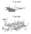
- Figs. 4(a) and 4(b) shows another embodiment, wherein the drop chute of the raw material-feeding apparatus for a rotary hearth in the invention is allowed to operate as the cutoff plate for preventing the falling raw material.
- Fig. 4(a) is a plan view and Fig. 4(b) is a perspective view.
- the falling raw material prevention cutoff plate 7 shown in Figs. 4 (a) and (b) is inclined and has the function of a drop chute of the raw material, too.
- the feed amount of the pellet can be adjusted by shaping the scraper 3 into the curve shape shown in Figs. 5(a) and 5(b).
- this scraper 3 is used, a greater amount of the raw material can be fed to the outer periphery of the rotary hearth than to the inner periphery. Consequently, deviation of the feed amount resulting from the area difference between the inner and outer peripheries of the rotary hearth can be corrected.
- the raw material 2 may be charged as a single layer into the flat belt conveyor 1 but when the raw material 2 is charged in two to five layers, the raw material 2 can be uniformly dispersed.
- the raw material 2 When the raw material 2 is charged in the single layer onto the flat belt conveyor 1, the raw material 2 can be uniformly dispersed into the furnace after it is charged onto the conveyor. When any gaps exist among the raw materials, however, the raw materials cannot be dispersed uniformly in some cases because only the gaps become smaller and non-uniformity of the raw materials occurs on the side of the scraper surface.
- the layers of raw materials bury the gaps. Consequently, the gaps do not occur among the raw materials but the raw material can be uniformly dispersed and charged into the furnace.
- the width capable of uniformly dispersing the raw material does not change even when the raw material 2 is charged onto the conveyor. It is therefore preferred to charge the raw materials in the range of two to five layers.
- the invention can provide a raw material-feeding apparatus capable of uniformly dispersing and feeding into a furnace raw materials that is likely to undergo dusting, deformation and mutual adhesion. Because 1 ⁇ the invention minimizes the impact to the agglomerated raw material, 2 ⁇ can feed the agglomerated raw material on the continuous line and 3 ⁇ can feed the agglomerated raw material into the rotary hearth furnace without interruption, the invention provides the following industrially remarkable effects.
Landscapes
- Engineering & Computer Science (AREA)
- Mechanical Engineering (AREA)
- General Engineering & Computer Science (AREA)
- Manufacture Of Iron (AREA)
- Tunnel Furnaces (AREA)
- Furnace Charging Or Discharging (AREA)
Abstract
Description
Claims (6)
- A raw material-feeding apparatus for a rotary hearth furnace, for feeding raw materials to a rotary hearth furnace by using a flat belt conveyor, characterized in that a scraper for guiding the raw materials on said flat belt conveyor to a side surface of said flat belt conveyor is arranged obliquely to a traveling direction of said flat belt conveyor.
- A raw material-feeding apparatus for a rotary hearth furnace according to claim 1, wherein said scrapers for guiding the raw materials on said flat belt conveyor to the side surface of said flat belt conveyor are disposed on both sides of said flat belt conveyor.
- A raw material-feeding apparatus for a rotary hearth furnace according to claim 1 or 2, wherein a gap between entrance portions of said scraper for guiding the pellets on said flat belt conveyor to the side surface of said flat belt conveyor is adjustable.
- A raw material-feeding apparatus for a rotary hearth furnace according to claim 1 or 2, wherein said scraper for guiding the raw materials on said flat belt conveyor to the side surface of said flat belt conveyor is shaped into a curve shape.
- A raw material-feeding apparatus for a rotary hearth furnace according to any of claims 1 through 4, wherein the raw materials are charged in one layer onto said flat belt conveyor.
- A raw material-feeding apparatus for a rotary hearth furnace according to any of claims 1 through 4, wherein the raw materials are charged in two to five layers onto said flat belt conveyor.
Applications Claiming Priority (3)
| Application Number | Priority Date | Filing Date | Title |
|---|---|---|---|
| JP2002339370A JP4212873B2 (en) | 2002-11-22 | 2002-11-22 | Raw material supply equipment for rotary hearth furnace |
| JP2002339370 | 2002-11-22 | ||
| PCT/JP2003/014944 WO2004048869A1 (en) | 2002-11-22 | 2003-11-21 | Material feeding apparatus for rotary hearth furnace |
Publications (3)
| Publication Number | Publication Date |
|---|---|
| EP1580508A1 true EP1580508A1 (en) | 2005-09-28 |
| EP1580508A4 EP1580508A4 (en) | 2006-08-16 |
| EP1580508B1 EP1580508B1 (en) | 2013-04-03 |
Family
ID=32375772
Family Applications (1)
| Application Number | Title | Priority Date | Filing Date |
|---|---|---|---|
| EP03774157A Expired - Lifetime EP1580508B1 (en) | 2002-11-22 | 2003-11-21 | Material feeding apparatus for rotary hearth furnace |
Country Status (7)
| Country | Link |
|---|---|
| US (1) | US7311519B2 (en) |
| EP (1) | EP1580508B1 (en) |
| JP (1) | JP4212873B2 (en) |
| KR (1) | KR100664004B1 (en) |
| CN (1) | CN100443844C (en) |
| TW (1) | TWI226424B (en) |
| WO (1) | WO2004048869A1 (en) |
Families Citing this family (5)
| Publication number | Priority date | Publication date | Assignee | Title |
|---|---|---|---|---|
| JP4567999B2 (en) * | 2004-03-23 | 2010-10-27 | 新日本製鐵株式会社 | Raw material transfer charging equipment for rotary hearth furnace |
| CN102864301B (en) * | 2012-10-17 | 2013-11-06 | 连云港市东茂矿业有限公司 | Automatic production line of directly-reduced ferronickel |
| CN103557698B (en) * | 2013-11-13 | 2015-08-19 | 赵作标 | Energy-conserving and environment-protective full-automatic electric heating rotary kiln |
| CN104864722B (en) * | 2015-05-21 | 2016-08-24 | 苏州汇科机电设备有限公司 | Saggar powder rotates scraping device |
| WO2020246479A1 (en) * | 2019-06-03 | 2020-12-10 | Jx金属株式会社 | Raw material discharge device, method of processing of electronic/electrical device component scrap, and method of raw material discharge for electronic/electrical device component scrap |
Family Cites Families (14)
| Publication number | Priority date | Publication date | Assignee | Title |
|---|---|---|---|---|
| JPS5120377A (en) * | 1974-08-09 | 1976-02-18 | Toyoda Automatic Loom Works | Ryujobutsuno hansohoko tenkansochi |
| JPH0437122A (en) | 1990-06-01 | 1992-02-07 | Fujitsu Ltd | Inspecting method for x-ray mask |
| JPH0739848Y2 (en) * | 1990-07-24 | 1995-09-13 | 三菱重工業株式会社 | Bottle collecting conveyor |
| BE1006456A6 (en) * | 1992-11-09 | 1994-09-06 | Centre Rech Metallurgique | Distribution device for granular substances loaded onto an ore agglomerationstrip |
| LU90072B1 (en) * | 1997-05-30 | 1998-12-01 | Wurth Paul Sa | Charging device for a rotary hearth furnace |
| JPH1112621A (en) * | 1997-06-27 | 1999-01-19 | Sumitomo Metal Ind Ltd | Method and apparatus for charging reduced iron production raw material |
| US5895215A (en) * | 1997-10-14 | 1999-04-20 | Maumee Research & Engineering, Inc. | Charging apparatus for a rotary hearth furnance |
| IT1304366B1 (en) * | 1998-04-29 | 2001-03-15 | Demag Italimpianti S P A Ora S | DISTRIBUTOR FEEDER DEVICE FOR ROTATING PLATFORMS, IN PARTICULAR FOR ROTATING SOLE OVENS. |
| JPH11322039A (en) * | 1998-05-12 | 1999-11-24 | Ishikawajima Harima Heavy Ind Co Ltd | Air levitated belt conveyor |
| JPH11337265A (en) | 1998-05-27 | 1999-12-10 | Daido Steel Co Ltd | Mechanism for charging pellet to rotary hearth |
| JP2000247435A (en) * | 1999-02-23 | 2000-09-12 | Kawasaki Steel Corp | Conveyance intermediate discharge device for belt conveyor |
| EP1178277A1 (en) * | 2000-04-25 | 2002-02-06 | BMH Claudius Peters GmbH | Process and installation to homogenize the expelled fired matter stream from a rotary drum furnace to the cooler |
| US6406662B1 (en) * | 2000-06-09 | 2002-06-18 | Maumee Research & Engineering, Incorporated | Rotary hearth furnace with charge slot air shield |
| US20020053307A1 (en) * | 2000-10-31 | 2002-05-09 | Natsuo Ishiwata | Method for discharging reduced product from a moveable-hearth furnace and a discharging device |
-
2002
- 2002-11-22 JP JP2002339370A patent/JP4212873B2/en not_active Expired - Fee Related
-
2003
- 2003-11-21 WO PCT/JP2003/014944 patent/WO2004048869A1/en not_active Ceased
- 2003-11-21 KR KR1020057009251A patent/KR100664004B1/en not_active Expired - Fee Related
- 2003-11-21 TW TW092132778A patent/TWI226424B/en not_active IP Right Cessation
- 2003-11-21 EP EP03774157A patent/EP1580508B1/en not_active Expired - Lifetime
- 2003-11-21 US US10/535,903 patent/US7311519B2/en not_active Expired - Fee Related
- 2003-11-21 CN CNB2003801038326A patent/CN100443844C/en not_active Expired - Fee Related
Also Published As
| Publication number | Publication date |
|---|---|
| JP4212873B2 (en) | 2009-01-21 |
| US20060035193A1 (en) | 2006-02-16 |
| WO2004048869A1 (en) | 2004-06-10 |
| JP2004170042A (en) | 2004-06-17 |
| TW200419125A (en) | 2004-10-01 |
| KR100664004B1 (en) | 2007-01-03 |
| EP1580508B1 (en) | 2013-04-03 |
| CN1714266A (en) | 2005-12-28 |
| CN100443844C (en) | 2008-12-17 |
| EP1580508A4 (en) | 2006-08-16 |
| US7311519B2 (en) | 2007-12-25 |
| TWI226424B (en) | 2005-01-11 |
| KR20050085120A (en) | 2005-08-29 |
Similar Documents
| Publication | Publication Date | Title |
|---|---|---|
| US7311519B2 (en) | Raw material feeding apparatus for rotary hearth furnace | |
| EP0961094B1 (en) | Feeding and distributing device for rotary platforms, particularly for rotary-hearth furnaces | |
| EP1957679B1 (en) | Bucket or star feeder, combined system, and method for operating said feeder | |
| US20040119210A1 (en) | Sealing mechanism of feeding device | |
| US5568734A (en) | Double layer cooler | |
| US9180521B2 (en) | Method for producing granular metallic iron | |
| JP2005226113A (en) | Method for charging sintering raw material | |
| JP4178079B2 (en) | Granular reduced metal production method and production apparatus thereof | |
| AU2008238146B2 (en) | Method and device for separating or classifying material to be fed | |
| KR100361742B1 (en) | Charging Method and Apparatus of Raw Material in sintering Machine | |
| CN201106987Y (en) | Apparatus for feeding and distributing material for rotary hearth furnace panoramic table | |
| EP0787809B1 (en) | Apparatus for charging raw sinter mix to sintering machine | |
| JP4567999B2 (en) | Raw material transfer charging equipment for rotary hearth furnace | |
| EP2009379A1 (en) | Screw conveyor for discharging reduced iron from rotary hearth reduction furnace | |
| JP6859676B2 (en) | Raw material charging equipment for rotary hearth furnaces and raw material charging methods for rotary hearth furnaces | |
| JP2001347228A (en) | Massive raw material sieving apparatus and sieving method | |
| KR101010640B1 (en) | Homogeneous Dispersion Unit in Sintered Steel Screening Chute | |
| CN112497823A (en) | Preforming guiding device that production powder coating used | |
| JP7468553B2 (en) | Conveyor chute and method for transporting raw materials for iron making using the same | |
| CN213825970U (en) | Automatic sorting device for sintering furnace grate bars | |
| SU735893A1 (en) | Apparatus for charging material on conveyer-type machine | |
| JP2002155309A (en) | Ejecting device in movable furnace hearth type heat treatment furnace and its operation method | |
| JP2005024129A (en) | Discharge device | |
| CN118936079A (en) | A double-chamber vertical kiln and calcining process | |
| KR20160008766A (en) | Discharging chutes for dispensing carried materials |
Legal Events
| Date | Code | Title | Description |
|---|---|---|---|
| PUAI | Public reference made under article 153(3) epc to a published international application that has entered the european phase |
Free format text: ORIGINAL CODE: 0009012 |
|
| 17P | Request for examination filed |
Effective date: 20050617 |
|
| AK | Designated contracting states |
Kind code of ref document: A1 Designated state(s): AT BE BG CH CY CZ DE DK EE ES FI FR GB GR HU IE IT LI LU MC NL PT RO SE SI SK TR |
|
| RAP1 | Party data changed (applicant data changed or rights of an application transferred) |
Owner name: NIPPON STEEL CORPORATION Owner name: NITTETSU PLANT DESIGNING CORPORATION |
|
| RBV | Designated contracting states (corrected) |
Designated state(s): FR IT |
|
| REG | Reference to a national code |
Ref country code: DE Ref legal event code: 8566 |
|
| A4 | Supplementary search report drawn up and despatched |
Effective date: 20060714 |
|
| 17Q | First examination report despatched |
Effective date: 20100201 |
|
| GRAP | Despatch of communication of intention to grant a patent |
Free format text: ORIGINAL CODE: EPIDOSNIGR1 |
|
| RIC1 | Information provided on ipc code assigned before grant |
Ipc: F27D 3/00 20060101ALI20120626BHEP Ipc: F27B 3/18 20060101AFI20120626BHEP Ipc: F27D 3/12 20060101ALI20120626BHEP Ipc: F27B 7/32 20060101ALI20120626BHEP |
|
| GRAS | Grant fee paid |
Free format text: ORIGINAL CODE: EPIDOSNIGR3 |
|
| RAP1 | Party data changed (applicant data changed or rights of an application transferred) |
Owner name: NITTETSU PLANT DESIGNING CORPORATION Owner name: NIPPON STEEL & SUMITOMO METAL CORPORATION |
|
| GRAA | (expected) grant |
Free format text: ORIGINAL CODE: 0009210 |
|
| RAP1 | Party data changed (applicant data changed or rights of an application transferred) |
Owner name: NIPPON STEEL & SUMIKIN ENGINEERING CO., LTD. Owner name: NS PLANT DESIGNING CORPORATION |
|
| AK | Designated contracting states |
Kind code of ref document: B1 Designated state(s): FR IT |
|
| PLBE | No opposition filed within time limit |
Free format text: ORIGINAL CODE: 0009261 |
|
| STAA | Information on the status of an ep patent application or granted ep patent |
Free format text: STATUS: NO OPPOSITION FILED WITHIN TIME LIMIT |
|
| 26N | No opposition filed |
Effective date: 20140106 |
|
| REG | Reference to a national code |
Ref country code: FR Ref legal event code: PLFP Year of fee payment: 13 |
|
| REG | Reference to a national code |
Ref country code: FR Ref legal event code: PLFP Year of fee payment: 14 |
|
| PGFP | Annual fee paid to national office [announced via postgrant information from national office to epo] |
Ref country code: FR Payment date: 20161014 Year of fee payment: 14 |
|
| PGFP | Annual fee paid to national office [announced via postgrant information from national office to epo] |
Ref country code: IT Payment date: 20161122 Year of fee payment: 14 |
|
| REG | Reference to a national code |
Ref country code: FR Ref legal event code: ST Effective date: 20180731 |
|
| PG25 | Lapsed in a contracting state [announced via postgrant information from national office to epo] |
Ref country code: FR Free format text: LAPSE BECAUSE OF NON-PAYMENT OF DUE FEES Effective date: 20171130 Ref country code: IT Free format text: LAPSE BECAUSE OF NON-PAYMENT OF DUE FEES Effective date: 20171121 |