EP1580484B1 - Remote staged furnace burner configurations and methods - Google Patents
Remote staged furnace burner configurations and methods Download PDFInfo
- Publication number
- EP1580484B1 EP1580484B1 EP05251726.5A EP05251726A EP1580484B1 EP 1580484 B1 EP1580484 B1 EP 1580484B1 EP 05251726 A EP05251726 A EP 05251726A EP 1580484 B1 EP1580484 B1 EP 1580484B1
- Authority
- EP
- European Patent Office
- Prior art keywords
- fuel gas
- furnace
- secondary fuel
- primary
- burners
- Prior art date
- Legal status (The legal status is an assumption and is not a legal conclusion. Google has not performed a legal analysis and makes no representation as to the accuracy of the status listed.)
- Active
Links
- 238000000034 method Methods 0.000 title claims description 34
- 239000002737 fuel gas Substances 0.000 claims description 153
- 239000000446 fuel Substances 0.000 claims description 57
- 239000000203 mixture Substances 0.000 claims description 44
- 238000002485 combustion reaction Methods 0.000 claims description 25
- 239000003546 flue gas Substances 0.000 claims description 22
- 230000008569 process Effects 0.000 claims description 21
- 230000015572 biosynthetic process Effects 0.000 claims description 13
- 238000007599 discharging Methods 0.000 claims description 7
- 239000007789 gas Substances 0.000 description 13
- 239000000567 combustion gas Substances 0.000 description 3
- MWUXSHHQAYIFBG-UHFFFAOYSA-N nitrogen oxide Inorganic materials O=[N] MWUXSHHQAYIFBG-UHFFFAOYSA-N 0.000 description 3
- IJGRMHOSHXDMSA-UHFFFAOYSA-N Atomic nitrogen Chemical compound N#N IJGRMHOSHXDMSA-UHFFFAOYSA-N 0.000 description 2
- 230000004888 barrier function Effects 0.000 description 2
- 239000003085 diluting agent Substances 0.000 description 2
- 239000007800 oxidant agent Substances 0.000 description 2
- 230000001590 oxidative effect Effects 0.000 description 2
- 238000012360 testing method Methods 0.000 description 2
- UGFAIRIUMAVXCW-UHFFFAOYSA-N Carbon monoxide Chemical compound [O+]#[C-] UGFAIRIUMAVXCW-UHFFFAOYSA-N 0.000 description 1
- 238000005336 cracking Methods 0.000 description 1
- 238000011161 development Methods 0.000 description 1
- 229910003460 diamond Inorganic materials 0.000 description 1
- 239000010432 diamond Substances 0.000 description 1
- 230000007613 environmental effect Effects 0.000 description 1
- 239000003344 environmental pollutant Substances 0.000 description 1
- 230000006872 improvement Effects 0.000 description 1
- 238000003780 insertion Methods 0.000 description 1
- 230000037431 insertion Effects 0.000 description 1
- 238000004519 manufacturing process Methods 0.000 description 1
- 239000011159 matrix material Substances 0.000 description 1
- 229910052757 nitrogen Inorganic materials 0.000 description 1
- 231100000719 pollutant Toxicity 0.000 description 1
- 230000005855 radiation Effects 0.000 description 1
- 238000002407 reforming Methods 0.000 description 1
- 238000012546 transfer Methods 0.000 description 1
Images


Classifications
-
- F—MECHANICAL ENGINEERING; LIGHTING; HEATING; WEAPONS; BLASTING
- F23—COMBUSTION APPARATUS; COMBUSTION PROCESSES
- F23C—METHODS OR APPARATUS FOR COMBUSTION USING FLUID FUEL OR SOLID FUEL SUSPENDED IN A CARRIER GAS OR AIR
- F23C5/00—Disposition of burners with respect to the combustion chamber or to one another; Mounting of burners in combustion apparatus
- F23C5/08—Disposition of burners
-
- A—HUMAN NECESSITIES
- A61—MEDICAL OR VETERINARY SCIENCE; HYGIENE
- A61H—PHYSICAL THERAPY APPARATUS, e.g. DEVICES FOR LOCATING OR STIMULATING REFLEX POINTS IN THE BODY; ARTIFICIAL RESPIRATION; MASSAGE; BATHING DEVICES FOR SPECIAL THERAPEUTIC OR HYGIENIC PURPOSES OR SPECIFIC PARTS OF THE BODY
- A61H15/00—Massage by means of rollers, balls, e.g. inflatable, chains, or roller chains
- A61H15/0078—Massage by means of rollers, balls, e.g. inflatable, chains, or roller chains power-driven
-
- A—HUMAN NECESSITIES
- A61—MEDICAL OR VETERINARY SCIENCE; HYGIENE
- A61H—PHYSICAL THERAPY APPARATUS, e.g. DEVICES FOR LOCATING OR STIMULATING REFLEX POINTS IN THE BODY; ARTIFICIAL RESPIRATION; MASSAGE; BATHING DEVICES FOR SPECIAL THERAPEUTIC OR HYGIENIC PURPOSES OR SPECIFIC PARTS OF THE BODY
- A61H7/00—Devices for suction-kneading massage; Devices for massaging the skin by rubbing or brushing not otherwise provided for
- A61H7/007—Kneading
-
- F—MECHANICAL ENGINEERING; LIGHTING; HEATING; WEAPONS; BLASTING
- F23—COMBUSTION APPARATUS; COMBUSTION PROCESSES
- F23C—METHODS OR APPARATUS FOR COMBUSTION USING FLUID FUEL OR SOLID FUEL SUSPENDED IN A CARRIER GAS OR AIR
- F23C6/00—Combustion apparatus characterised by the combination of two or more combustion chambers or combustion zones, e.g. for staged combustion
- F23C6/04—Combustion apparatus characterised by the combination of two or more combustion chambers or combustion zones, e.g. for staged combustion in series connection
- F23C6/042—Combustion apparatus characterised by the combination of two or more combustion chambers or combustion zones, e.g. for staged combustion in series connection with fuel supply in stages
-
- F—MECHANICAL ENGINEERING; LIGHTING; HEATING; WEAPONS; BLASTING
- F23—COMBUSTION APPARATUS; COMBUSTION PROCESSES
- F23C—METHODS OR APPARATUS FOR COMBUSTION USING FLUID FUEL OR SOLID FUEL SUSPENDED IN A CARRIER GAS OR AIR
- F23C6/00—Combustion apparatus characterised by the combination of two or more combustion chambers or combustion zones, e.g. for staged combustion
- F23C6/04—Combustion apparatus characterised by the combination of two or more combustion chambers or combustion zones, e.g. for staged combustion in series connection
- F23C6/045—Combustion apparatus characterised by the combination of two or more combustion chambers or combustion zones, e.g. for staged combustion in series connection with staged combustion in a single enclosure
-
- F—MECHANICAL ENGINEERING; LIGHTING; HEATING; WEAPONS; BLASTING
- F23—COMBUSTION APPARATUS; COMBUSTION PROCESSES
- F23C—METHODS OR APPARATUS FOR COMBUSTION USING FLUID FUEL OR SOLID FUEL SUSPENDED IN A CARRIER GAS OR AIR
- F23C9/00—Combustion apparatus characterised by arrangements for returning combustion products or flue gases to the combustion chamber
- F23C9/006—Combustion apparatus characterised by arrangements for returning combustion products or flue gases to the combustion chamber the recirculation taking place in the combustion chamber
-
- F—MECHANICAL ENGINEERING; LIGHTING; HEATING; WEAPONS; BLASTING
- F23—COMBUSTION APPARATUS; COMBUSTION PROCESSES
- F23D—BURNERS
- F23D14/00—Burners for combustion of a gas, e.g. of a gas stored under pressure as a liquid
- F23D14/12—Radiant burners
- F23D14/125—Radiant burners heating a wall surface to incandescence
-
- A—HUMAN NECESSITIES
- A61—MEDICAL OR VETERINARY SCIENCE; HYGIENE
- A61H—PHYSICAL THERAPY APPARATUS, e.g. DEVICES FOR LOCATING OR STIMULATING REFLEX POINTS IN THE BODY; ARTIFICIAL RESPIRATION; MASSAGE; BATHING DEVICES FOR SPECIAL THERAPEUTIC OR HYGIENIC PURPOSES OR SPECIFIC PARTS OF THE BODY
- A61H15/00—Massage by means of rollers, balls, e.g. inflatable, chains, or roller chains
- A61H2015/0007—Massage by means of rollers, balls, e.g. inflatable, chains, or roller chains with balls or rollers rotating about their own axis
- A61H2015/0014—Massage by means of rollers, balls, e.g. inflatable, chains, or roller chains with balls or rollers rotating about their own axis cylinder-like, i.e. rollers
-
- A—HUMAN NECESSITIES
- A61—MEDICAL OR VETERINARY SCIENCE; HYGIENE
- A61H—PHYSICAL THERAPY APPARATUS, e.g. DEVICES FOR LOCATING OR STIMULATING REFLEX POINTS IN THE BODY; ARTIFICIAL RESPIRATION; MASSAGE; BATHING DEVICES FOR SPECIAL THERAPEUTIC OR HYGIENIC PURPOSES OR SPECIFIC PARTS OF THE BODY
- A61H2201/00—Characteristics of apparatus not provided for in the preceding codes
- A61H2201/12—Driving means
- A61H2201/1207—Driving means with electric or magnetic drive
- A61H2201/1215—Rotary drive
Definitions
- the present invention relates to remote staged furnace burner configurations, and more particularly, to the placement of secondary fuel gas nozzles separate and remote from the burners resulting in lower NO x production.
- Radiant wall burner furnaces generally include radiant wall burners having central fuel gas-air mixture burner tubes surrounded by annular refractory tiles which are adapted for insertion into openings in the furnace wall.
- the burner nozzles discharge and bum fuel gas-air mixtures in directions generally parallel and adjacent to the internal faces of the refractory tiles.
- the combustion of the fuel gas-air mixtures causes the faces of the burner tiles to radiate heat, e.g., to process tubes, and undesirable flame impingement on the process tubes is thereby avoided.
- Radiant wall burners are typically installed in several rows along a furnace wall. This type of configuration is usually designed to provide uniform heat input to the process tubes from the wall area comprising the radiant wall burner matrix.
- Vertical cylindrical furnaces cabin furnaces and other similar furnaces such as boilers are also well known.
- Vertical cylindrical furnaces generally include an array of burners on the floor of the furnace that discharge and burn fuel gas-air mixtures vertically.
- Process tubes are positioned vertically around the burners and adjacent to the cylindrical wall of the furnace whereby heat from the burning fuel gas-air mixtures radiates to the process tubes.
- Cabin furnaces and other similar furnaces generally include an array of two or more burners on the rectangular floor of the furnace that discharge and burn fuel gas-air mixtures vertically.
- Horizontal process tubes are arranged on opposite walls of the furnace which are parallel to the burner array. Additional process tubes can also be arranged adjacent to the top of the furnace. Heat from the burning fuel gas-air mixtures radiates to the process tubes.
- staged or secondary fuel burner apparatus and methods wherein all of the air and some of the fuel is burned in a first zone and the remaining fuel is burned in a second downstream zone.
- an excess of air in the first zone functions as a diluent which lowers the temperature of the burning gases and thereby reduces the formation of NO x .
- furnace flue gases function as a diluent to lower the temperature of the burning secondary fuel and thereby reduce the formation of NO x .
- staged burner designs have also been developed wherein the burner combusts a primary fuel lean mixture of fuel gas and air and stage fuel risers discharge secondary fuel.
- the location of the secondary fuel risers can vary, depending on the manufacturer and type of burner, but they are typically located around and adjacent to the perimeter of the primary burner.
- U.S. Patent No. 4,496,306 discloses a method comprising injecting a primary fuel and air into a furnace to bum the fuel and form a first-stage combustion zone. Specific details are given for box furnace applications. The air in the furnace is being supplied at a rate in excess of the stoichiometric rate required for the combustion of the fuel.
- 5,573,391 discloses a burner apparatus and method for reducing nitrogen oxides that are formed during combustion of gaseous fuel.
- Primary gaseous fuel and excess oxidant are premixed to form a fuel/oxidant mixture which is introduced into and combusted within a primary combustion zone.
- a low NO x producing vertical cylindrical furnace having a cylindrical wall and a floor
- a primary burner on the floor of the furnace for vertically introducing a lean combustible fuel gas-air mixture into a combustion zone adjacent to the primary burner; a secondary fuel gas nozzle, said secondary fuel gas nozzle located separate and remote from the primary burner such that the introduced secondary fuel gas initially mixes with flue gases in the furnace prior to mixing with the fuel gas-air mixture from the primary burner in a combustion zone and combusting therein with excess air, thereby lowering the temperature of the burning fuel gas an reducing the formation of NO x ; and a plurality of process tubes positioned vertically around the primary burner and adjacent to the cylindrical wall of the furnace whereby heat from the burning
- secondary fuel gas is introduced into the secondary fuel gas nozzles in an amount that constitutes a substantial portion of the total fuel provided to the combustion zone by the lean primary fuel gas-air mixtures and the secondary fuel gas.
- the secondary fuel gas nozzles are positioned on the furnace wall or on the furnace floor, or both, and direct secondary fuel gas to various locations including a location on the opposite side of the combustion zone from the burners. As a result, NO x levels in the combustion gases leaving the furnace are substantially reduced.
- secondary fuel gas nozzles are also located on the furnace floor, and the furnace includes floor burners (also referred to as hearth burners) with or without secondary fuel gas nozzles on the floor.
- the secondary fuel gas nozzles have tips with at least one fuel delivery orifice designed to eject fuel gas at an angle relative to the longitudinal axis of the nozzle. More preferably, the secondary fuel gas nozzles have multiple fuel delivery orifices.
- the invention also provides a method of burning fuel gas and air in a vertical cylindrical furnace having a cylindrical wall, a floor, a primary burner disposed on the floor and a plurality of process tubes positioned vertically around the primary burner and adjacent to the cylindrical wall whereby flue gases of reduced NO x content are formed comprising the steps of: (a) providing a lean fuel gas-air mixture to the primary burner; (b) causing the fuel gas-air mixture to be vertically discharged from the primary burner whereby the mixture is burned at a relatively low temperature in a combustion zone and flue gases having low NO x content are formed therefrom and heat from the burning fuel gas-air mixture radiates to the process tubes; and (c) providing secondary fuel gas to a secondary fuel gas nozzle whereby the secondary fuel gas is discharged from the secondary fuel gas nozzle, mixes with flue gases in the furnace prior to mixing with the fuel gas-air mixture from the primary burner in a combustion zone and combusting therein with excess air from the primary burner, lowers the temperature of the burning fuel gas and reduces
- FIG. 1 illustrates the gas flow pattern in a radiant wall furnace using conventional staging with secondary fuel gas in the center of each burner.
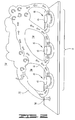
- FIG. 2 illustrates the gas flow pattern of the present invention in a radiant wall furnace with remote staging of fuel gas.
- FIG. 3 is a remote staging burner configuration on the wall of a radiant wall furnace.
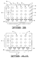
- FIGS. 4A - 4D illustrate other remote staging configurations on the wall of a radiant wall furnace.
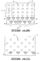
- FIGS. 5A - 5F illustrate remote staging configurations in a radiant wall furnace that include additional secondary fuel gas discharge nozzles on the furnace floor with and without floor burners.
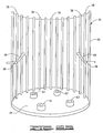
- FIGS. 6A - 6C illustrate preferred remote staging configurations in a vertical cylindrical furnace.
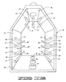
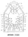
- FIGS. 7A - 7C illustrate remote staging configurations in a cabin furnace.
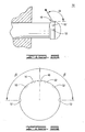
- FIG. 8 is a side view of a preferred secondary fuel gas discharge nozzle for use in accordance with this invention.
- FIG. 9 is a top view of the secondary fuel gas discharge nozzle of FIG. 8 .
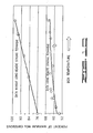
- FIG. 10 is a graph comparing NO x emissions from a test furnace with and without the remote staging technique of this invention.
- the present invention relates to vertical cylindrical furnaces and methods of burning fuel gas and air in vertical cylindrical furnaces. Other types of furnace are described below and this description is useful in aiding understanding of the present invention.
- a radiant wall furnace burner configuration utilizes rows of multiple radiant wall burners that include annular refractory tiles and bum fuel gas lean air mixtures connected to a wall of the furnace in a regular spacing and an array of secondary fuel gas nozzles located separate and remote from the radiant wall burners with means for introducing secondary fuel gas into the secondary fuel gas nozzles and wherein the secondary fuel gas constitutes a substantial portion of the total fuel provided to the combustion zone by the fuel gas-air mixtures and the secondary fuel gas.
- the secondary fuel gas nozzles are positioned on the furnace wall adjacent to the rows of radiant wall burners or on the furnace floor, or both, and direct secondary fuel gas to various locations including a location on the opposite side of the combustion zone from the radiant wall burners. As a result, NO x levels in the combustion gases leaving the furnace are reduced.
- FIG. 1 depicts a traditional burner column 11 of staged fuel radiant wall burners 10.
- the staged fuel radiant wall burners 10 consist of radiant wall burner tips 12 which are provided with a fuel gas lean mixture of primary fuel gas and air.
- Secondary fuel gas risers 14 supply the secondary fuel gas tips 16 thereof with fuel gas.
- the location of the secondary fuel gas tips 16 is typically in the centers of the radiant wall burner tips 12 as shown in FIG. 1 , or around the perimeters of the radiant wall burner tips 12.
- the fuel gas-air streams exiting the burner tips 12 form barriers 18 and 20 and encapsulate or surround the secondary fuel gas 22.
- the fuel gas-air barriers 18 and 20 around the secondary fuel gas 22 prevents sufficient entrainment of flue gas 24 resulting in increased NO x emissions.
- the secondary fuel gas from or adjacent each radiant wall burner 10 is eliminated. Instead, the secondary fuel gas is injected into the furnace at a remote location. As shown in FIG. 2 , by moving the secondary fuel gas to a remote secondary fuel gas nozzle 26 located, for example, below the burner column 11, the secondary fuel gas 22 is able to mix with the furnace flue gases 24 prior to mixing with the fuel gas-air mixture 18 in the combustion zone 28. It has been found that by using one or more remote secondary fuel gas nozzles 26 positioned at remote locations and providing secondary fuel gas patterns, reduced NO x emissions are achieved as well as improved flame quality compared to state-of-the-art radiant wall burner designs.
- an improved radiant wall furnace burner configuration is illustrated and generally designated by the numeral 30.
- Rows 32 of multiple radiant wall burners 10 are inserted in a wall 31 of the furnace.
- the radiant wall burners 10 discharge fuel gas-air mixtures in radial directions across the face of the furnace wall 31. Radiant heat from the wall, as well as thermal radiation from the hot gases, is transferred, for example, to process tubes or other process equipment designed for heat transfer.
- Each radiant wall burner 10 is provided a mixture of primary fuel gas and air wherein the flow rate of air is greater than stoichiometry relative to the primary gas.
- the rate of air is in the range of from about 105% to about 120% of the stoichiometric flow rate required to completely combust the primary and secondary fuel gas.
- Secondary fuel gas is discharged into the furnace by way of secondary fuel gas nozzles 26.
- the burner configuration of FIG. 3 shows the secondary fuel gas nozzles 26 arranged in a row 32 with each secondary fuel gas nozzle positioned below a column 34 of radiant wall burners.
- the secondary fuel gas nozzles are made to discharge fuel gas in a direction generally toward the radiant wall burners as will be explained in detail below.
- FIGS. 4A - 4D Additional examples of patterns are illustrated in FIGS. 4A - 4D .
- Rows of radiant wall burners 10 can be approximately parallel, the burners 10 can be approximately evenly spaced in columns 34 and the secondary fuel gas nozzles 26 can be positioned in a single row 32 with each nozzle directly below a radiant wall burner 10 in the row above as shown in FIG. 3 , or offset as shown in FIG. 4A .
- FIG. 4A As shown in FIG.
- the radiant wall burners 10 are in columns approximately parallel, the radiant wall burners 10 are approximately evenly spaced in columns 34 and the secondary fuel gas nozzles 26 positioned below the radiant wall burners 10 are in two rows, an upper row 36 and a lower row 38, wherein each secondary fuel gas nozzle of the upper row 36 is below a burner in the row above and wherein each secondary fuel gas nozzle of the lower row 38 is midway between the horizontal positions of the secondary fuel gas nozzles directly above it in row 36.
- the radiant wall burners 10 are offset halfway from one another, resulting in a diamond shaped pattern with the secondary fuel gas nozzles 26 located below the radiant wall burners and continuing the pattern.
- FIG. 4C shows that the radiant wall burners 10 are offset halfway from one another, resulting in a diamond shaped pattern with the secondary fuel gas nozzles 26 located below the radiant wall burners and continuing the pattern.
- furnace walls 31 with the radiant wall burners 10 and secondary fuel gas nozzles 26 connected thereto are described above as if the walls are vertical, but it is to be understood that the walls can be at an angle from vertical or the walls can be horizontal.
- FIGS. 5A - 5F alternate arrangements of secondary fuel gas nozzles 26 are shown with and without floor burners 54 (also referred to as hearth burners).
- floor burners 54 also referred to as hearth burners.
- FIGS. 5A and 5B rows of multiple radiant wall burners 10 are inserted in a wall 31 of a furnace. As previously mentioned, the burners 10 discharge fuel gas-air mixtures in directions across the face of the furnace wall 31.
- Each radiant wall burner is provided a mixture of primary fuel gas and air wherein the flow rate of air is greater than stoichiometry relative to the primary gas, i.e., in the range of from about 105% to about 120% of the stoichiometric flow rate.
- Secondary fuel gas is discharged into the furnace by way of secondary fuel gas nozzles 26 disposed below the columns of radiant gas burners 10.
- secondary fuel gas nozzles 26 are disposed in the floor of the furnace to provide additional secondary fuel gas that mixes with excess air and furnace flue gases whereby low NO x levels are produced.
- FIGS. 5C and 5D a similar arrangement of radiant wall burners 10 and secondary fuel gas nozzles 26 is illustrated.
- floor burners 54 are provided adjacent to the wall 31 that mix fuel gas with an excess of air, and the secondary fuel gas nozzles 26 discharge fuel gas toward both the radiant wall burners and the floor burners whereby the secondary fuel gas readily mixes with furnace flue gases and excess air so that low NO x levels are produced.
- additional secondary fuel gas nozzles can be provided in the floor of the furnace to mix with furnace flue gases and the excess air produced by the floor burners whereby low NO x levels are produced.
- radiant wall burners 10 and separate and remote secondary fuel gas nozzles can be utilized in radiant wall gas burner furnaces to reduce NO x levels in furnace flue gases.
- FIGS. 6A , 6B and 6C improved vertical cylindrical furnace burner configurations of this invention are illustrated.
- a vertical cylindrical furnace 56 is shown having vertical process tubes 58 disposed around and adjacent to the cylindrical wall 60 of the furnace.
- Four primary burners 62 are disposed on the floor 64 of the furnace, but as is understood by those skilled in the art, fewer or more burners 62 can be used.
- the burners 62 discharge and burn fuel gas lean-air mixtures vertically.
- a secondary fuel gas nozzle 66 is provided on the furnace floor positioned in a location separate and remote from the primary burners 62. When required, additional secondary fuel gas nozzles 66 can be provided on the furnace floor 64.
- the secondary fuel gas is directed vertically by the secondary fuel gas nozzles 66 so that it mixes with flue gases in the furnace and then combusts with excess air to thereby lower the temperature of the burning fuel gas and reduce the formation of NO x .
- two secondary fuel gas nozzles 68 are attached to opposite sides of the cylindrical wall 60 of the furnace 56 above the burners 62.
- the secondary fuel gas is directed by the secondary fuel gas nozzles 68 at upward angles above the burners 62 whereby the secondary fuel gas mixes with flue gases in the furnace and then combusts with excess air to thereby lower the temperature of the burning fuel gas and reduce the formation of NO x .
- both secondary fuel gas nozzles 66 and 68 can be utilized when required to reduce the formation of NO x .
- FIGS. 7A , 7B and 7C improved cabin and other similar furnace burner configurations are illustrated.
- a cabin furnace 70 is shown having horizontal process tubes 72 disposed on opposite sides 74 and the top 76.
- Three primary burners 78 are disposed on the floor 80 of the furnace, but fewer or more can be used.
- the burners 78 discharge and burn fuel gas lean-air mixtures vertically.
- secondary fuel gas nozzles 82 that direct secondary fuel gas vertically as shown by the arrows 83 are provided on the furnace floor on opposite sides of the burner 78.
- the secondary fuel gas mixes with flue gases in the furnace and then combusts with excess air to thereby lower the temperature of the burning fuel gas and reduce the formation of NO x .
- secondary fuel gas nozzles are omitted on the floor 80 of the furnace 70. Instead, secondary fuel gas nozzles 84 are provided on the opposite walls 74 between process tubes 72. As shown by the arrows 86, the secondary fuel gas is directed at upward angles above the burners 78 whereby the secondary fuel gas mixes with flue gases in the furnace and then combusts with excess air to lower the temperature of the burning fuel gas and reduce the formation of NO x .
- both secondary fuel gas nozzles 82 and 84 can be utilized when required to reduce the formation of NO x .
- furnace burner configurations of this invention can be utilized in any vertical cylinder furnace to reduce NO x formation.
- the total fuel gas-air mixture flowing through the furnace burners contains less than about 80% of the total fuel supplied to the combustion zone 28.
- the secondary fuel gas nozzles are disposed on the furnace floor or walls extending about 2.5 to about 30.5 cm (about 1 to about 12 inches) into the furnace interior. Fuel gas is preferably supplied at a pressure in the range of from about 138 to about 345 kPa (about 20 to about 50 psig).
- the secondary fuel gas nozzles positioned on the walls of furnaces and illustrated in FIGS. 1 through 5 are shown in detail in FIGS. 8 and 9 .
- the nozzles can have single fuel gas delivery openings 48 therein for discharging the flow of secondary fuel gas into the furnace.
- the openings 48 discharge secondary fuel gas towards or away from a wall of a furnace at an angle ⁇ in the general range of about 60° to about 120° from the longitudinal axis.
- the secondary fuel gas nozzles can also include additional side delivery openings 52 for discharging secondary fuel gas in various directions over angles ⁇ in the range of from about 10° to about 180° from both sides of a vertical plane through the longitudinal axis, and more preferably at angles in the range of about 20° to about 150°.
- the secondary fuel gas nozzles When the secondary fuel gas nozzles are positioned on the walls or floors of vertical cylindrical furnaces, they can include fuel gas delivery openings therein that discharge secondary fuel gas in multiple directions.
- the test furnace utilized an array of 12 radiant wall burners arranged in 3 columns of 4 burners each. The burners were spaced 127 centimeters (50 inches) apart in each column and the columns were spaced 93 centimeters (36.5 inches) apart. The furnace was operated while supplying secondary gas to the center of the radiant wall burners and the NO x in the furnace off gas was measured over time. The furnace was then operated after removing secondary gas from the burner centers and conducting the secondary gas to remote nozzles located adjacent to the columns of radiant wall burners.
- FIG. 8 is a plot comparing NO x emissions from the furnace with and without the remote staging configuration. The data demonstrate that NO x emissions are reduced by 50% using the remote staging configuration.
Landscapes
- Engineering & Computer Science (AREA)
- Chemical & Material Sciences (AREA)
- Combustion & Propulsion (AREA)
- Mechanical Engineering (AREA)
- General Engineering & Computer Science (AREA)
- Health & Medical Sciences (AREA)
- Pain & Pain Management (AREA)
- Epidemiology (AREA)
- Physical Education & Sports Medicine (AREA)
- Rehabilitation Therapy (AREA)
- Life Sciences & Earth Sciences (AREA)
- Animal Behavior & Ethology (AREA)
- General Health & Medical Sciences (AREA)
- Public Health (AREA)
- Veterinary Medicine (AREA)
- Dermatology (AREA)
- Combustion Of Fluid Fuel (AREA)
Applications Claiming Priority (2)
| Application Number | Priority Date | Filing Date | Title |
|---|---|---|---|
| US807977 | 2004-03-24 | ||
| US10/807,977 US7153129B2 (en) | 2004-01-15 | 2004-03-24 | Remote staged furnace burner configurations and methods |
Publications (3)
| Publication Number | Publication Date |
|---|---|
| EP1580484A2 EP1580484A2 (en) | 2005-09-28 |
| EP1580484A3 EP1580484A3 (en) | 2006-04-05 |
| EP1580484B1 true EP1580484B1 (en) | 2013-08-07 |
Family
ID=34862063
Family Applications (1)
| Application Number | Title | Priority Date | Filing Date |
|---|---|---|---|
| EP05251726.5A Active EP1580484B1 (en) | 2004-03-24 | 2005-03-22 | Remote staged furnace burner configurations and methods |
Country Status (10)
| Country | Link |
|---|---|
| US (1) | US7153129B2 (ja) |
| EP (1) | EP1580484B1 (ja) |
| JP (1) | JP4750441B2 (ja) |
| KR (1) | KR100879169B1 (ja) |
| CN (1) | CN1721763B (ja) |
| AR (1) | AR049626A1 (ja) |
| BR (1) | BRPI0501106A (ja) |
| CA (1) | CA2502130C (ja) |
| MX (1) | MXPA05003125A (ja) |
| TW (1) | TWI330242B (ja) |
Families Citing this family (7)
| Publication number | Priority date | Publication date | Assignee | Title |
|---|---|---|---|---|
| US20070231761A1 (en) * | 2006-04-03 | 2007-10-04 | Lee Rosen | Integration of oxy-fuel and air-fuel combustion |
| US7878798B2 (en) * | 2006-06-14 | 2011-02-01 | John Zink Company, Llc | Coanda gas burner apparatus and methods |
| US8113825B2 (en) * | 2007-02-06 | 2012-02-14 | Neal Ormond | Computer-controlled pyrotechnic matrix display |
| US7819656B2 (en) * | 2007-05-18 | 2010-10-26 | Lummus Technology Inc. | Heater and method of operation |
| US8573965B2 (en) * | 2007-11-28 | 2013-11-05 | Air Products And Chemicals, Inc. | Method of operating a pyrolysis heater for reduced NOx |
| US9222410B2 (en) | 2011-04-13 | 2015-12-29 | General Electric Company | Power plant |
| US11927345B1 (en) | 2019-03-01 | 2024-03-12 | XRG Technologies, LLC | Method and device to reduce emissions of nitrogen oxides and increase heat transfer in fired process heaters |
Family Cites Families (64)
| Publication number | Priority date | Publication date | Assignee | Title |
|---|---|---|---|---|
| JPS5270432A (en) * | 1975-12-08 | 1977-06-11 | Hitachi Zosen Corp | Method of two-stage burning for suppressing generation of nitrogen oxi des |
| US4496306A (en) * | 1978-06-09 | 1985-01-29 | Hitachi Shipbuilding & Engineering Co., Ltd. | Multi-stage combustion method for inhibiting formation of nitrogen oxides |
| JPS6119304Y2 (ja) * | 1980-12-29 | 1986-06-11 | ||
| JPS57139015U (ja) * | 1981-02-25 | 1982-08-31 | ||
| JPS59147913A (ja) * | 1983-02-14 | 1984-08-24 | Inax Corp | 熱交換装置 |
| US4652232A (en) * | 1983-05-16 | 1987-03-24 | John Zink Co. | Apparatus and method to add kinetic energy to a low pressure waste gas flare burner |
| US4781578A (en) * | 1984-01-24 | 1988-11-01 | John Zink Company | Pilot burner apparatus |
| US4702691A (en) * | 1984-03-19 | 1987-10-27 | John Zink Company | Even flow radial burner tip |
| US4686352B1 (en) * | 1984-04-27 | 1993-12-14 | Sunbeam Corporation | Electronic pressing iron |
| US4900244A (en) * | 1984-08-29 | 1990-02-13 | John Zink Company | Gas flaring method and apparatus |
| USD290215S (en) * | 1984-10-19 | 1987-06-09 | John Zink Company | Coffeemaker |
| USD290218S (en) * | 1984-11-13 | 1987-06-09 | John Zink Company | Food processor base |
| USD289600S (en) * | 1985-03-21 | 1987-05-05 | John Zink Company | Can opener housing |
| USD289963S (en) * | 1985-03-21 | 1987-05-26 | John Zink Company | Carving knife housing |
| USD290889S (en) * | 1985-05-31 | 1987-07-14 | John Zink Company | Steam iron |
| US4902484A (en) * | 1985-07-18 | 1990-02-20 | John Zink Company | Oxygen injector means for secondary reformer |
| US4661685A (en) * | 1985-09-06 | 1987-04-28 | John Zink Company | Electronic pressing iron |
| US4664617A (en) * | 1985-11-26 | 1987-05-12 | John Zink Company | Method and burner apparatus for flaring inert vitiated waste gases |
| US4975042A (en) * | 1985-11-26 | 1990-12-04 | John Zink Company | Method and burner apparatus for flaring inert vitiated waste gases |
| US4683369A (en) * | 1986-02-05 | 1987-07-28 | John Zink Company | Hand held electric hair dryer |
| US4673798A (en) * | 1986-04-02 | 1987-06-16 | John Zink Company | Dual temperature electric curling iron having a safety shut-off circuit |
| US4737100A (en) * | 1986-04-30 | 1988-04-12 | John Zink Company | Duct burner apparatus |
| US4663849A (en) * | 1986-07-21 | 1987-05-12 | John Zink Company | Combination can opener/knife sharpener with pivotal mounting |
| US4952137A (en) * | 1986-09-08 | 1990-08-28 | John Zink Company | Flare gas burner |
| US4788918A (en) * | 1987-11-20 | 1988-12-06 | John Zink Company | Solids incineration process and system |
| US4798150A (en) * | 1987-11-25 | 1989-01-17 | John Zink Company | Apparatus for handling ash |
| EP0317692A1 (de) * | 1987-11-26 | 1989-05-31 | Franz Plasser Bahnbaumaschinen-Industriegesellschaft m.b.H. | Stopfpickel für Gleisstopfmaschinen |
| US4838184A (en) * | 1988-05-23 | 1989-06-13 | John Zink Company | Method and apparatus for disposing of landfill produced pollutants |
| US4922838A (en) | 1988-10-11 | 1990-05-08 | John Zink Company | Thermal processor for solid and fluid waste materials |
| JPH06103083B2 (ja) * | 1988-10-14 | 1994-12-14 | 日立造船株式会社 | ラジアントガスバーナ |
| US4870910A (en) * | 1989-01-25 | 1989-10-03 | John Zink Company | Waste incineration method and apparatus |
| US4901652A (en) * | 1989-04-10 | 1990-02-20 | John Zink Company | Accumulating and conveying incinerator ash |
| US5195844A (en) * | 1989-10-19 | 1993-03-23 | Oil Stop, Inc. | Floating barrier method and apparatus |
| US5154735A (en) * | 1990-03-29 | 1992-10-13 | John Zink Company, A Division Of Koch Engineering Co., Inc. | Process for recovering hydrocarbons from air-hydrocarbon vapor mixtures |
| US5098282A (en) * | 1990-09-07 | 1992-03-24 | John Zink Company | Methods and apparatus for burning fuel with low NOx formation |
| US5154596A (en) * | 1990-09-07 | 1992-10-13 | John Zink Company, A Division Of Koch Engineering Company, Inc. | Methods and apparatus for burning fuel with low NOx formation |
| JP2613146B2 (ja) * | 1991-11-26 | 1997-05-21 | 旭化成工業株式会社 | スラリー触媒用管型反応器 |
| US5180302A (en) * | 1992-02-28 | 1993-01-19 | John Zink Company, A Division Of Koch Engineering Company, Inc. | Radiant gas burner and method |
| US5238395A (en) * | 1992-03-27 | 1993-08-24 | John Zink Company | Low nox gas burner apparatus and methods |
| US5195884A (en) * | 1992-03-27 | 1993-03-23 | John Zink Company, A Division Of Koch Engineering Company, Inc. | Low NOx formation burner apparatus and methods |
| US5345771A (en) * | 1993-03-25 | 1994-09-13 | John Zink Company, A Division Of Koch Engineering Company, Inc. | Process for recovering condensable compounds from inert gas-condensable compound vapor mixtures |
| US5573391A (en) * | 1994-10-13 | 1996-11-12 | Gas Research Institute | Method for reducing nitrogen oxides |
| US5718573A (en) * | 1994-12-27 | 1998-02-17 | Carrier Corporation | Flashback resistant burner |
| US5688115A (en) * | 1995-06-19 | 1997-11-18 | Shell Oil Company | System and method for reduced NOx combustion |
| US5709541A (en) | 1995-06-26 | 1998-01-20 | Selas Corporation Of America | Method and apparatus for reducing NOx emissions in a gas burner |
| US5813849A (en) * | 1996-08-07 | 1998-09-29 | John Zink Company, A Division Of Koch-Glitshc, Inc. | Flame detection apparatus and methods |
| US5810575A (en) * | 1997-03-05 | 1998-09-22 | Schwartz; Robert E. | Flare apparatus and methods |
| US6000930A (en) * | 1997-05-12 | 1999-12-14 | Altex Technologies Corporation | Combustion process and burner apparatus for controlling NOx emissions |
| US5951741A (en) * | 1998-03-27 | 1999-09-14 | John Zink Company | Hydrocarbon vapor recovery processes and apparatus |
| US6062848A (en) * | 1998-05-29 | 2000-05-16 | Coen Company, Inc. | Vibration-resistant low NOx burner |
| JP2002518656A (ja) * | 1998-06-17 | 2002-06-25 | ジョン ジンク カンパニー,エルエルシー | 低NOx及び低COバーナ並びにその作動方法 |
| US6231334B1 (en) * | 1998-11-24 | 2001-05-15 | John Zink Company | Biogas flaring unit |
| US6383461B1 (en) * | 1999-10-26 | 2002-05-07 | John Zink Company, Llc | Fuel dilution methods and apparatus for NOx reduction |
| US6383462B1 (en) * | 1999-10-26 | 2002-05-07 | John Zink Company, Llc | Fuel dilution methods and apparatus for NOx reduction |
| US6478239B2 (en) * | 2000-01-25 | 2002-11-12 | John Zink Company, Llc | High efficiency fuel oil atomizer |
| ATE278153T1 (de) * | 2000-03-13 | 2004-10-15 | John Zink Co Llc | Wandstrahlungsbrenner mit niedriger nox-emission |
| US6524098B1 (en) * | 2000-05-16 | 2003-02-25 | John Zink Company Llc | Burner assembly with swirler formed from concentric components |
| US6796790B2 (en) * | 2000-09-07 | 2004-09-28 | John Zink Company Llc | High capacity/low NOx radiant wall burner |
| US6422858B1 (en) * | 2000-09-11 | 2002-07-23 | John Zink Company, Llc | Low NOx apparatus and methods for burning liquid and gaseous fuels |
| US6616442B2 (en) * | 2000-11-30 | 2003-09-09 | John Zink Company, Llc | Low NOx premix burner apparatus and methods |
| US6379146B1 (en) * | 2001-04-09 | 2002-04-30 | Zeeco, Inc. | Flow divider for radiant wall burner |
| US6464492B1 (en) * | 2001-04-26 | 2002-10-15 | John Zink Company, Llc | Methods of utilizing boiler blowdown for reducing NOx |
| US6486375B1 (en) * | 2001-05-02 | 2002-11-26 | John Zink Company, Llc | Process for recovering hydrocarbons from inert gas-hydrocarbon vapor mixtures |
| US6565361B2 (en) * | 2001-06-25 | 2003-05-20 | John Zink Company, Llc | Methods and apparatus for burning fuel with low NOx formation |
-
2004
- 2004-03-24 US US10/807,977 patent/US7153129B2/en not_active Expired - Lifetime
-
2005
- 2005-03-22 EP EP05251726.5A patent/EP1580484B1/en active Active
- 2005-03-22 KR KR1020050023487A patent/KR100879169B1/ko not_active IP Right Cessation
- 2005-03-22 MX MXPA05003125A patent/MXPA05003125A/es active IP Right Grant
- 2005-03-22 JP JP2005081061A patent/JP4750441B2/ja not_active Expired - Fee Related
- 2005-03-23 AR ARP050101156A patent/AR049626A1/es active IP Right Grant
- 2005-03-23 CA CA002502130A patent/CA2502130C/en not_active Expired - Fee Related
- 2005-03-24 TW TW094109190A patent/TWI330242B/zh not_active IP Right Cessation
- 2005-03-24 CN CN2005100589036A patent/CN1721763B/zh active Active
- 2005-03-24 BR BR0501106-0A patent/BRPI0501106A/pt not_active IP Right Cessation
Also Published As
| Publication number | Publication date |
|---|---|
| CA2502130C (en) | 2008-11-18 |
| JP2005274126A (ja) | 2005-10-06 |
| BRPI0501106A (pt) | 2005-11-01 |
| US7153129B2 (en) | 2006-12-26 |
| AR049626A1 (es) | 2006-08-23 |
| KR100879169B1 (ko) | 2009-01-16 |
| JP4750441B2 (ja) | 2011-08-17 |
| TW200602593A (en) | 2006-01-16 |
| KR20060044519A (ko) | 2006-05-16 |
| CN1721763A (zh) | 2006-01-18 |
| CN1721763B (zh) | 2011-06-01 |
| EP1580484A3 (en) | 2006-04-05 |
| MXPA05003125A (es) | 2005-11-04 |
| CA2502130A1 (en) | 2005-09-24 |
| US20050158684A1 (en) | 2005-07-21 |
| TWI330242B (en) | 2010-09-11 |
| EP1580484A2 (en) | 2005-09-28 |
Similar Documents
| Publication | Publication Date | Title |
|---|---|---|
| CA2492670C (en) | Remote staged radiant wall furnace burner configurations and methods | |
| EP1580484B1 (en) | Remote staged furnace burner configurations and methods | |
| EP1426681B9 (en) | Compact low NOx gas burner apparatus and methods | |
| US8703064B2 (en) | Hydrocabon cracking furnace with steam addition to lower mono-nitrogen oxide emissions | |
| EP0210314B1 (en) | Method and apparatus for burning fuel | |
| EP0076036B1 (en) | Method and apparatus for burning fuel in stages | |
| US7198482B2 (en) | Compact low NOx gas burner apparatus and methods | |
| KR100770625B1 (ko) | 퍼니스 연소 시스템 및 퍼니스에서 연료를 연소시키는 방법 | |
| US20120037146A1 (en) | Low nox burner | |
| KR100566806B1 (ko) | 다화염 예혼합 버너 | |
| KR19980028131U (ko) | 직화식 소결점화로용 슬릿 버너 |
Legal Events
| Date | Code | Title | Description |
|---|---|---|---|
| PUAI | Public reference made under article 153(3) epc to a published international application that has entered the european phase |
Free format text: ORIGINAL CODE: 0009012 |
|
| AK | Designated contracting states |
Kind code of ref document: A2 Designated state(s): AT BE BG CH CY CZ DE DK EE ES FI FR GB GR HU IE IS IT LI LT LU MC NL PL PT RO SE SI SK TR |
|
| AX | Request for extension of the european patent |
Extension state: AL BA HR LV MK YU |
|
| PUAL | Search report despatched |
Free format text: ORIGINAL CODE: 0009013 |
|
| AK | Designated contracting states |
Kind code of ref document: A3 Designated state(s): AT BE BG CH CY CZ DE DK EE ES FI FR GB GR HU IE IS IT LI LT LU MC NL PL PT RO SE SI SK TR |
|
| AX | Request for extension of the european patent |
Extension state: AL BA HR LV MK YU |
|
| 17P | Request for examination filed |
Effective date: 20060703 |
|
| AKX | Designation fees paid |
Designated state(s): AT BE BG CH CY CZ DE DK EE ES FI FR GB GR HU IE IS IT LI LT LU MC NL PL PT RO SE SI SK TR |
|
| 17Q | First examination report despatched |
Effective date: 20100526 |
|
| GRAP | Despatch of communication of intention to grant a patent |
Free format text: ORIGINAL CODE: EPIDOSNIGR1 |
|
| RIN1 | Information on inventor provided before grant (corrected) |
Inventor name: WAIBEL, RICHARD T. Inventor name: RUIZ, ROBERTO Inventor name: BUSSMAN, WESLEY R. Inventor name: CHUNG, I-PING Inventor name: BAUKAL, CHARLES E. JR. Inventor name: CHELLAPPAN, SELLAMUTHA G. |
|
| GRAS | Grant fee paid |
Free format text: ORIGINAL CODE: EPIDOSNIGR3 |
|
| GRAA | (expected) grant |
Free format text: ORIGINAL CODE: 0009210 |
|
| AK | Designated contracting states |
Kind code of ref document: B1 Designated state(s): AT BE BG CH CY CZ DE DK EE ES FI FR GB GR HU IE IS IT LI LT LU MC NL PL PT RO SE SI SK TR |
|
| REG | Reference to a national code |
Ref country code: GB Ref legal event code: FG4D |
|
| REG | Reference to a national code |
Ref country code: AT Ref legal event code: REF Ref document number: 625929 Country of ref document: AT Kind code of ref document: T Effective date: 20130815 Ref country code: CH Ref legal event code: EP |
|
| REG | Reference to a national code |
Ref country code: IE Ref legal event code: FG4D |
|
| REG | Reference to a national code |
Ref country code: DE Ref legal event code: R096 Ref document number: 602005040718 Country of ref document: DE Effective date: 20131002 |
|
| REG | Reference to a national code |
Ref country code: NL Ref legal event code: T3 |
|
| REG | Reference to a national code |
Ref country code: AT Ref legal event code: MK05 Ref document number: 625929 Country of ref document: AT Kind code of ref document: T Effective date: 20130807 |
|
| REG | Reference to a national code |
Ref country code: LT Ref legal event code: MG4D |
|
| PG25 | Lapsed in a contracting state [announced via postgrant information from national office to epo] |
Ref country code: PT Free format text: LAPSE BECAUSE OF FAILURE TO SUBMIT A TRANSLATION OF THE DESCRIPTION OR TO PAY THE FEE WITHIN THE PRESCRIBED TIME-LIMIT Effective date: 20131209 Ref country code: AT Free format text: LAPSE BECAUSE OF FAILURE TO SUBMIT A TRANSLATION OF THE DESCRIPTION OR TO PAY THE FEE WITHIN THE PRESCRIBED TIME-LIMIT Effective date: 20130807 Ref country code: CY Free format text: LAPSE BECAUSE OF FAILURE TO SUBMIT A TRANSLATION OF THE DESCRIPTION OR TO PAY THE FEE WITHIN THE PRESCRIBED TIME-LIMIT Effective date: 20130619 Ref country code: SE Free format text: LAPSE BECAUSE OF FAILURE TO SUBMIT A TRANSLATION OF THE DESCRIPTION OR TO PAY THE FEE WITHIN THE PRESCRIBED TIME-LIMIT Effective date: 20130807 Ref country code: IS Free format text: LAPSE BECAUSE OF FAILURE TO SUBMIT A TRANSLATION OF THE DESCRIPTION OR TO PAY THE FEE WITHIN THE PRESCRIBED TIME-LIMIT Effective date: 20131207 Ref country code: LT Free format text: LAPSE BECAUSE OF FAILURE TO SUBMIT A TRANSLATION OF THE DESCRIPTION OR TO PAY THE FEE WITHIN THE PRESCRIBED TIME-LIMIT Effective date: 20130807 |
|
| PG25 | Lapsed in a contracting state [announced via postgrant information from national office to epo] |
Ref country code: PL Free format text: LAPSE BECAUSE OF FAILURE TO SUBMIT A TRANSLATION OF THE DESCRIPTION OR TO PAY THE FEE WITHIN THE PRESCRIBED TIME-LIMIT Effective date: 20130807 Ref country code: ES Free format text: LAPSE BECAUSE OF FAILURE TO SUBMIT A TRANSLATION OF THE DESCRIPTION OR TO PAY THE FEE WITHIN THE PRESCRIBED TIME-LIMIT Effective date: 20130807 Ref country code: FI Free format text: LAPSE BECAUSE OF FAILURE TO SUBMIT A TRANSLATION OF THE DESCRIPTION OR TO PAY THE FEE WITHIN THE PRESCRIBED TIME-LIMIT Effective date: 20130807 Ref country code: SI Free format text: LAPSE BECAUSE OF FAILURE TO SUBMIT A TRANSLATION OF THE DESCRIPTION OR TO PAY THE FEE WITHIN THE PRESCRIBED TIME-LIMIT Effective date: 20130807 Ref country code: GR Free format text: LAPSE BECAUSE OF FAILURE TO SUBMIT A TRANSLATION OF THE DESCRIPTION OR TO PAY THE FEE WITHIN THE PRESCRIBED TIME-LIMIT Effective date: 20131108 |
|
| PG25 | Lapsed in a contracting state [announced via postgrant information from national office to epo] |
Ref country code: CY Free format text: LAPSE BECAUSE OF FAILURE TO SUBMIT A TRANSLATION OF THE DESCRIPTION OR TO PAY THE FEE WITHIN THE PRESCRIBED TIME-LIMIT Effective date: 20130807 |
|
| PG25 | Lapsed in a contracting state [announced via postgrant information from national office to epo] |
Ref country code: SK Free format text: LAPSE BECAUSE OF FAILURE TO SUBMIT A TRANSLATION OF THE DESCRIPTION OR TO PAY THE FEE WITHIN THE PRESCRIBED TIME-LIMIT Effective date: 20130807 Ref country code: CZ Free format text: LAPSE BECAUSE OF FAILURE TO SUBMIT A TRANSLATION OF THE DESCRIPTION OR TO PAY THE FEE WITHIN THE PRESCRIBED TIME-LIMIT Effective date: 20130807 Ref country code: DK Free format text: LAPSE BECAUSE OF FAILURE TO SUBMIT A TRANSLATION OF THE DESCRIPTION OR TO PAY THE FEE WITHIN THE PRESCRIBED TIME-LIMIT Effective date: 20130807 Ref country code: RO Free format text: LAPSE BECAUSE OF FAILURE TO SUBMIT A TRANSLATION OF THE DESCRIPTION OR TO PAY THE FEE WITHIN THE PRESCRIBED TIME-LIMIT Effective date: 20130807 Ref country code: EE Free format text: LAPSE BECAUSE OF FAILURE TO SUBMIT A TRANSLATION OF THE DESCRIPTION OR TO PAY THE FEE WITHIN THE PRESCRIBED TIME-LIMIT Effective date: 20130807 |
|
| PLBE | No opposition filed within time limit |
Free format text: ORIGINAL CODE: 0009261 |
|
| STAA | Information on the status of an ep patent application or granted ep patent |
Free format text: STATUS: NO OPPOSITION FILED WITHIN TIME LIMIT |
|
| 26N | No opposition filed |
Effective date: 20140508 |
|
| REG | Reference to a national code |
Ref country code: DE Ref legal event code: R097 Ref document number: 602005040718 Country of ref document: DE Effective date: 20140508 |
|
| PG25 | Lapsed in a contracting state [announced via postgrant information from national office to epo] |
Ref country code: LU Free format text: LAPSE BECAUSE OF FAILURE TO SUBMIT A TRANSLATION OF THE DESCRIPTION OR TO PAY THE FEE WITHIN THE PRESCRIBED TIME-LIMIT Effective date: 20140322 |
|
| REG | Reference to a national code |
Ref country code: CH Ref legal event code: PL |
|
| REG | Reference to a national code |
Ref country code: IE Ref legal event code: MM4A |
|
| PG25 | Lapsed in a contracting state [announced via postgrant information from national office to epo] |
Ref country code: LI Free format text: LAPSE BECAUSE OF NON-PAYMENT OF DUE FEES Effective date: 20140331 Ref country code: IE Free format text: LAPSE BECAUSE OF NON-PAYMENT OF DUE FEES Effective date: 20140322 Ref country code: CH Free format text: LAPSE BECAUSE OF NON-PAYMENT OF DUE FEES Effective date: 20140331 |
|
| REG | Reference to a national code |
Ref country code: FR Ref legal event code: PLFP Year of fee payment: 12 |
|
| PG25 | Lapsed in a contracting state [announced via postgrant information from national office to epo] |
Ref country code: BG Free format text: LAPSE BECAUSE OF FAILURE TO SUBMIT A TRANSLATION OF THE DESCRIPTION OR TO PAY THE FEE WITHIN THE PRESCRIBED TIME-LIMIT Effective date: 20130807 Ref country code: MC Free format text: LAPSE BECAUSE OF FAILURE TO SUBMIT A TRANSLATION OF THE DESCRIPTION OR TO PAY THE FEE WITHIN THE PRESCRIBED TIME-LIMIT Effective date: 20130807 |
|
| PG25 | Lapsed in a contracting state [announced via postgrant information from national office to epo] |
Ref country code: TR Free format text: LAPSE BECAUSE OF FAILURE TO SUBMIT A TRANSLATION OF THE DESCRIPTION OR TO PAY THE FEE WITHIN THE PRESCRIBED TIME-LIMIT Effective date: 20130807 Ref country code: HU Free format text: LAPSE BECAUSE OF FAILURE TO SUBMIT A TRANSLATION OF THE DESCRIPTION OR TO PAY THE FEE WITHIN THE PRESCRIBED TIME-LIMIT; INVALID AB INITIO Effective date: 20050322 |
|
| REG | Reference to a national code |
Ref country code: FR Ref legal event code: PLFP Year of fee payment: 13 |
|
| REG | Reference to a national code |
Ref country code: FR Ref legal event code: PLFP Year of fee payment: 14 |
|
| PGFP | Annual fee paid to national office [announced via postgrant information from national office to epo] |
Ref country code: FR Payment date: 20230208 Year of fee payment: 19 |
|
| PGFP | Annual fee paid to national office [announced via postgrant information from national office to epo] |
Ref country code: IT Payment date: 20230213 Year of fee payment: 19 Ref country code: BE Payment date: 20230216 Year of fee payment: 19 |
|
| P01 | Opt-out of the competence of the unified patent court (upc) registered |
Effective date: 20230528 |
|
| PGFP | Annual fee paid to national office [announced via postgrant information from national office to epo] |
Ref country code: NL Payment date: 20240108 Year of fee payment: 20 |
|
| PGFP | Annual fee paid to national office [announced via postgrant information from national office to epo] |
Ref country code: DE Payment date: 20231229 Year of fee payment: 20 Ref country code: GB Payment date: 20240108 Year of fee payment: 20 |