EP1580449A2 - Fourche téléscopique pour véhicule, de préférence une moto - Google Patents
Fourche téléscopique pour véhicule, de préférence une moto Download PDFInfo
- Publication number
- EP1580449A2 EP1580449A2 EP05445005A EP05445005A EP1580449A2 EP 1580449 A2 EP1580449 A2 EP 1580449A2 EP 05445005 A EP05445005 A EP 05445005A EP 05445005 A EP05445005 A EP 05445005A EP 1580449 A2 EP1580449 A2 EP 1580449A2
- Authority
- EP
- European Patent Office
- Prior art keywords
- piston
- leak
- damping
- function
- chamber
- Prior art date
- Legal status (The legal status is an assumption and is not a legal conclusion. Google has not performed a legal analysis and makes no representation as to the accuracy of the status listed.)
- Withdrawn
Links
- 238000013016 damping Methods 0.000 claims abstract description 27
- 230000006835 compression Effects 0.000 claims abstract description 16
- 238000007906 compression Methods 0.000 claims abstract description 16
- 230000009977 dual effect Effects 0.000 claims abstract description 5
- 230000000694 effects Effects 0.000 claims 1
- 238000010276 construction Methods 0.000 description 6
- 238000006073 displacement reaction Methods 0.000 description 4
- 239000000654 additive Substances 0.000 description 2
- 239000010720 hydraulic oil Substances 0.000 description 2
- 238000012986 modification Methods 0.000 description 1
- 230000004048 modification Effects 0.000 description 1
- 238000007789 sealing Methods 0.000 description 1
Images


Classifications
-
- F—MECHANICAL ENGINEERING; LIGHTING; HEATING; WEAPONS; BLASTING
- F16—ENGINEERING ELEMENTS AND UNITS; GENERAL MEASURES FOR PRODUCING AND MAINTAINING EFFECTIVE FUNCTIONING OF MACHINES OR INSTALLATIONS; THERMAL INSULATION IN GENERAL
- F16F—SPRINGS; SHOCK-ABSORBERS; MEANS FOR DAMPING VIBRATION
- F16F9/00—Springs, vibration-dampers, shock-absorbers, or similarly-constructed movement-dampers using a fluid or the equivalent as damping medium
- F16F9/32—Details
- F16F9/34—Special valve constructions; Shape or construction of throttling passages
- F16F9/342—Throttling passages operating with metering pins
-
- F—MECHANICAL ENGINEERING; LIGHTING; HEATING; WEAPONS; BLASTING
- F16—ENGINEERING ELEMENTS AND UNITS; GENERAL MEASURES FOR PRODUCING AND MAINTAINING EFFECTIVE FUNCTIONING OF MACHINES OR INSTALLATIONS; THERMAL INSULATION IN GENERAL
- F16F—SPRINGS; SHOCK-ABSORBERS; MEANS FOR DAMPING VIBRATION
- F16F9/00—Springs, vibration-dampers, shock-absorbers, or similarly-constructed movement-dampers using a fluid or the equivalent as damping medium
- F16F9/32—Details
- F16F9/44—Means on or in the damper for manual or non-automatic adjustment; such means combined with temperature correction
-
- F—MECHANICAL ENGINEERING; LIGHTING; HEATING; WEAPONS; BLASTING
- F16—ENGINEERING ELEMENTS AND UNITS; GENERAL MEASURES FOR PRODUCING AND MAINTAINING EFFECTIVE FUNCTIONING OF MACHINES OR INSTALLATIONS; THERMAL INSULATION IN GENERAL
- F16F—SPRINGS; SHOCK-ABSORBERS; MEANS FOR DAMPING VIBRATION
- F16F9/00—Springs, vibration-dampers, shock-absorbers, or similarly-constructed movement-dampers using a fluid or the equivalent as damping medium
- F16F9/32—Details
- F16F9/50—Special means providing automatic damping adjustment, i.e. self-adjustment of damping by particular sliding movements of a valve element, other than flexions or displacement of valve discs; Special means providing self-adjustment of spring characteristics
- F16F9/512—Means responsive to load action, i.e. static load on the damper or dynamic fluid pressure changes in the damper, e.g. due to changes in velocity
Definitions
- the present invention relates to a telescopic fork leg for a vehicle, preferably a motorcycle.
- the telescopic fork leg comprises mutually displaceable inner and outer tube parts and a damping arrangement for damping the relative movements of the tube parts.
- the damping arrangement comprises tubular and coaxially disposed units and a piston (main piston) which belongs to the first outer tube part and is arranged to operate in a chamber within the interior of the tubular units in the damping arrangement in a medium present in the chamber, which medium, in dependence on the speed of the piston or at piston speed above a certain value, passes between the top and bottom sides of the piston via passages and damping-influencing members, for example shims, by the side of the piston and/or via passages and damping-influencing members in the piston.
- the said speed or value is chosen with the said damping-influencing members, which can be activated to or from their fully closed positions in dependence on the choice or setting of the members in question.
- Alternatives to a motorcycle might be a scooter, a water-borne vehicle, etc.
- As the medium hydraulic oil with possible additives, gas, etc. may be utilized.
- the invention is primarily intended for use in connection with a pressurized telescopic front fork.
- the need has arisen to be able to provide a leak flow or bleed function arrangement which shall be present at low speeds between the telescopic parts or the telescopic tubes, which, in a known manner, are connected to or support the vehicle wheel in question (vehicle front wheel), runner, pontoon, etc. by means of a first telescopic part or telescopic tube and to the vehicle chassis by means of a second telescopic part or a second telescopic tube.
- the leak flow or the bleed function will reduce damping forces at low relative speeds between the telescopic parts, for example speeds from just above zero to about 0.1 metre/second.
- the leak flow function allows the vehicle wheel or equivalent, when the vehicle is driven over an uneven ground surface, to be essentially undamped at relatively low or low speeds between the wheel and the vehicle.
- the said leak flow function is applied and utilized in respect of telescopic forks, there is a need for the construction, despite the built-in leak flow function, to be carried out with conventional components and without substantial reconstructions of the telescopic fork leg as such. For instance, there may be a desire to put components belonging to the telescopic tube and damping arrangements to dual use. It is also imperative for the leak flow function to be able to be arranged such that it is easily adjustable, in which case the setting arrangement should be able to be realized for individual or coordinated setting in respect of two or more telescopic front fork legs.
- the object of the present invention is to solve, inter alia, all or some of the problems indicated above.
- a telescopic fork leg according to the invention may principally be deemed to be characterized in that, at piston speeds below the said value, one or more leak flow passages or leak flow paths are present, which lead from the said chamber on one side of the piston, via a gap between the outside of the inner tubular unit and within a second tubular unit disposed outside the inner unit in the damping arrangement, and one or more leak-flow-size-determining members, and back to the chamber on the other side of the piston, i.e. the passage(s) or path(s) lead past or to the side of the piston when the damping-influencing members have closed the passages through the piston.
- the said member(s) is/are arranged so as to be adjustable.
- a first leak flow path in the direction of compression of the tube parts, can be establishable by means of a first one-way valve function and a first leak-flow-determining member.
- a second leak flow path in the direction of expansion of the tube parts, can be establishable by means of a second one-way valve function and a second leak-flow-determining second member.
- the adjustment can in this case be carried out such that the first and second leak flows substantially correspond to one another in size or have different sizes.
- the said leak-flow-size-determining member can be provided with an adjustable bleed needle function, which is arranged so as to be adjustable from the outside of the leg.
- the said inner tube part can also have a dual function, by acting as the said tubular second unit in the damping arrangement and thereby operating with both strength-establishing and leak flow-conducting functions.
- the leg as such can form part of a telescopic front fork, the two legs of which can have substantially similar construction and working.
- the respective leg can therefore operate with one or more adjustably arranged leak flow paths, the adjustment being able to be made from the outside of the particular leg.
- the new function(s) can easily be integrated with existing front fork designs.
- the said dual use of components can, for example, involve a telescopic fork tube in the actual telescopic function being utilized both as a strength-producing member and as a leak-flow-conducting member.
- Conventional one-way valve functions can be utilized.
- the valve functions are in one embodiment pressure-direction-controlled, but can in principle be controlled differently, for example computer-controlled.
- the leak flow paths the displacement of medium between the piston sides can be guaranteed at relatively low piston speeds when the shims or equivalent have closed the passages through the piston.
- the leak flow is also arranged so as to be adjustable with the valves and it is possible with the setting function to assign the telescopic fork small or low damping forces in respect of small piston movements.
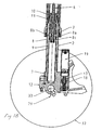
- FIG. 1A and 1B can be put together in order to indicate the below-specified construction principle for the telescopic leg.
- An outer tube with bushings, forming part of the leg, is denoted by 1.
- 2 denotes an inner tube and 3 denotes a bottom piece.
- a spring forming part of the leg is denoted by 4 and the leg comprises an adjusting member 5 for setting the spring bias.
- a piston rod is denoted by 6 and a piston holder is denoted by 7.
- the main piston of the telescopic leg is illustrated by 8.
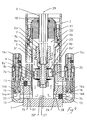
- the piston is provided in a known manner with one or more passages 8a and shims disposed on the side of the latter, a stack of compression shims having been denoted by 8b and a stack of return or expansion shims having been denoted by 8c.
- the leg is provided with a damping system, the inner tube of which has been denoted by 9.
- An inner seal assembly which seals between the piston rod and the inner tube of the damping system, has been labelled 10.
- An outer seal assembly which seals between the inner tube of the damping system and the outer tube of the damping system, is denoted by 11.
- 12 denotes a valve housing and 13 a one-way valve which can be opened only by compression leak flow around the said piston (main piston).
- a needle and a nozzle for adjusting compression leak flow around the piston are illustrated by 14.
- a one-way valve which can be opened only by return leak flow around the main piston has been labelled 15.
- Needle and nozzle adjusting return leak flow around the main piston have been denoted by 16.
- a piston with compression shim stack, only operative by the compression flow of the piston rod displacement, has been illustrated by 17.
- Needle and nozzle for adjusting the compression leak flow, around the piston 17, of the piston rod displacement have been denoted by 18.
- 19 denotes a gas tank of a type which is known per se. Part of the construction and functions of these and other components which have not been specified may be known per se.
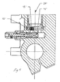
- Figures 2 and 3 show a first one-way valve 13 and a first bleed needle 14 and a second one-way valve 15 and a second bleed needle acting in the directions of compression and expansion of the leg.
- the piston 8 (the main piston) operates in a chamber 20', 20" in the inner tubular unit 2 of the front fork.
- the chamber part 20' is situated above the piston and the chamber part 20'' is situated below the piston. Up and down directions for the fork are of no intrinsic importance to the described working of the fork.
- the piston 8 operates in a medium present in the chamber 20', 20'', which medium has been symbolized with 21 and can be constituted by hydraulic oil with possible additives of a known kind. In the event of movements of the piston above a certain piston speed value, i.e.
- a gap 24 in which the leak flow path(s) also extend(s).
- the gap(s) is/are connected by substantially radial recesses 25 and 26 in the bottom piece 3 to one side of a respective leak-flow-size-determining member, which, in the illustrative embodiment, is constituted by a bleed needle 14 and 16 respectively.
- a first leak flow path 22 is present for the direction of compression, i.e. that direction for the tube parts of the telescopic leg which presses the tube parts towards one another.
- the first leak flow path is indicated by filled arrows.
- a second leak flow path 23 is denoted by open arrows and is attributable to the expansion direction or return direction between the tube parts.
- the other side of the respective bleed needle and its associated seat is connected to substantially radial ducts 27 and 28 in the bottom piece.
- the said ducts contain members which allow leak flow passage wholly or principally in only one direction and which, in the illustrative embodiment, consist of one-way valves 13 and 15.
- the said leak flow paths are also open at piston speeds at which the shims or equivalent are activated and are exerting their damping action.
- the size of the leak flow(s) is in this case tiny or small and does not substantially affect the damping function effected by the shims or equivalent.
- a first leak flow path 22 is therefore configured, in respect of compression, from the part-chamber 20'' on the bottom side of the piston, the radial recess 25, to the bottom side 14a of the bleed needle, via the bleed needle seat or the top side 14b of the bleed needle, the one-way valve 13, the radial recess 27, the gap 24 and the lateral recess 9a, and onward to the part-chamber 20'.
- a second leak flow path 23 is configured, in respect of expansion, from the part-chamber 20', via the recess 9b, the gap 24, the recess 26, the top side 16a and the bleed needle 16, to the bottom side 16b and via the one-way valve 15 and the radial recess 28, whence the second leak flow path 23 leads to the part-chamber 20'' below the piston.
- the arrangement of the one-way valves 13 and 15 means that the compression leak flow is prevented from affecting the expansion leak flow, and vice versa.
- the members which act upon the leak flows are arranged so as to be adjustable.
- the said bleed needles are adjustably provided with setting members, which, in the illustrative embodiment, are constituted by screw head settings 14c and 16c.
- the bleed needle arrangement extends substantially parallel with the longitudinal direction of the telescopic leg along the centre axis 29. The action of the setting members results in the adjustment or setting of the longitudinal displacement position of the bleed needle relative to the seat of the bleed needle, and hence of the size of the leak flow.
- the one-way valves 13 and 15 can comprise springs and sleeve-shaped sealing parts, balls and springs, computer-controlled elements, etc.
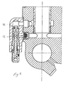
- FIG. 5 an arrangement is shown, in which the adjustment and setting members and the bleed needle 16 have been disposed, in the illustrative embodiment, substantially perpendicular to the longitudinal or centre axis 29 of the telescopic leg.
- the position of a one-way valve 15' is also evident from the figure.
- the valve housing has been denoted by 12' .
- the positionings of the valves do not, per se, affect the working of the damping system.
- FIG. 1A can be seen the application of the leg 1 to a chassis and to a partially shown further fork leg 30, which, in the illustrative embodiment, forms part, together with the leg 1, of a fork arrangement for the front wheel of a vehicle (motorcycle).
- the chassis has the notation 31 and the front wheel 32.
- the fastening to the chassis is realized by means of the outer tube and the wheel is secured to the inner tube 2.
- the wheel is secured at a fastening point 33 in the bottom piece.
- the two fork legs in the telescopic fork can be arranged identically.
- the respective fork leg can herein be provided with a leak flow arrangement in the compression and/or return directions.
- the respective leg(s) can be adjustable separately or in coordination.
Landscapes
- Engineering & Computer Science (AREA)
- General Engineering & Computer Science (AREA)
- Mechanical Engineering (AREA)
- Physics & Mathematics (AREA)
- Fluid Mechanics (AREA)
- Axle Suspensions And Sidecars For Cycles (AREA)
- Fluid-Damping Devices (AREA)
Applications Claiming Priority (2)
| Application Number | Priority Date | Filing Date | Title |
|---|---|---|---|
| SE0400782A SE526801C2 (sv) | 2004-03-24 | 2004-03-24 | Teleskopgaffelben för fordon, företrädesvis motorcykel |
| SE0400782 | 2004-03-24 |
Publications (2)
| Publication Number | Publication Date |
|---|---|
| EP1580449A2 true EP1580449A2 (fr) | 2005-09-28 |
| EP1580449A3 EP1580449A3 (fr) | 2006-03-08 |
Family
ID=32067533
Family Applications (1)
| Application Number | Title | Priority Date | Filing Date |
|---|---|---|---|
| EP05445005A Withdrawn EP1580449A3 (fr) | 2004-03-24 | 2005-02-10 | Fourche téléscopique pour véhicule, de préférence une moto |
Country Status (4)
| Country | Link |
|---|---|
| US (1) | US7255210B2 (fr) |
| EP (1) | EP1580449A3 (fr) |
| JP (1) | JP2005271913A (fr) |
| SE (1) | SE526801C2 (fr) |
Families Citing this family (30)
| Publication number | Priority date | Publication date | Assignee | Title |
|---|---|---|---|---|
| US10047817B2 (en) | 2009-01-07 | 2018-08-14 | Fox Factory, Inc. | Method and apparatus for an adjustable damper |
| US10060499B2 (en) | 2009-01-07 | 2018-08-28 | Fox Factory, Inc. | Method and apparatus for an adjustable damper |
| US8627932B2 (en) | 2009-01-07 | 2014-01-14 | Fox Factory, Inc. | Bypass for a suspension damper |
| US11306798B2 (en) | 2008-05-09 | 2022-04-19 | Fox Factory, Inc. | Position sensitive suspension damping with an active valve |
| US20100170760A1 (en) | 2009-01-07 | 2010-07-08 | John Marking | Remotely Operated Bypass for a Suspension Damper |
| US9033122B2 (en) | 2009-01-07 | 2015-05-19 | Fox Factory, Inc. | Method and apparatus for an adjustable damper |
| US9452654B2 (en) | 2009-01-07 | 2016-09-27 | Fox Factory, Inc. | Method and apparatus for an adjustable damper |
| US8393446B2 (en) | 2008-08-25 | 2013-03-12 | David M Haugen | Methods and apparatus for suspension lock out and signal generation |
| EP3666347B1 (fr) | 2008-11-25 | 2021-10-20 | Fox Factory, Inc. | Support de stockage utilisable par ordinateur de compétition virtuelle |
| US10036443B2 (en) | 2009-03-19 | 2018-07-31 | Fox Factory, Inc. | Methods and apparatus for suspension adjustment |
| US9422018B2 (en) | 2008-11-25 | 2016-08-23 | Fox Factory, Inc. | Seat post |
| US9140325B2 (en) | 2009-03-19 | 2015-09-22 | Fox Factory, Inc. | Methods and apparatus for selective spring pre-load adjustment |
| US12491961B2 (en) | 2008-11-25 | 2025-12-09 | Fox Factory, Inc. | Seat post |
| US12122205B2 (en) | 2009-01-07 | 2024-10-22 | Fox Factory, Inc. | Active valve for an internal bypass |
| US10821795B2 (en) | 2009-01-07 | 2020-11-03 | Fox Factory, Inc. | Method and apparatus for an adjustable damper |
| US11299233B2 (en) | 2009-01-07 | 2022-04-12 | Fox Factory, Inc. | Method and apparatus for an adjustable damper |
| US9038791B2 (en) | 2009-01-07 | 2015-05-26 | Fox Factory, Inc. | Compression isolator for a suspension damper |
| US8936139B2 (en) | 2009-03-19 | 2015-01-20 | Fox Factory, Inc. | Methods and apparatus for suspension adjustment |
| EP2312180B1 (fr) | 2009-10-13 | 2019-09-18 | Fox Factory, Inc. | Appareil pour contrôler un amortisseur hydraulique |
| US8672106B2 (en) | 2009-10-13 | 2014-03-18 | Fox Factory, Inc. | Self-regulating suspension |
| US10697514B2 (en) | 2010-01-20 | 2020-06-30 | Fox Factory, Inc. | Remotely operated bypass for a suspension damper |
| EP2402239B1 (fr) | 2010-07-02 | 2020-09-02 | Fox Factory, Inc. | Tige de selle réglable |
| EP2530355B1 (fr) | 2011-05-31 | 2019-09-04 | Fox Factory, Inc. | Appareil pour amortissement de suspension sensible au positionnement et/ou réglable |
| EP3567272B1 (fr) | 2011-09-12 | 2021-05-26 | Fox Factory, Inc. | Procédés et appareil de réglage de suspension |
| US11279199B2 (en) | 2012-01-25 | 2022-03-22 | Fox Factory, Inc. | Suspension damper with by-pass valves |
| US9103400B2 (en) * | 2012-05-09 | 2015-08-11 | Fox Factory, Inc. | Method and apparatus for an adjustable damper |
| US10330171B2 (en) | 2012-05-10 | 2019-06-25 | Fox Factory, Inc. | Method and apparatus for an adjustable damper |
| US9302729B1 (en) | 2014-01-13 | 2016-04-05 | Charles L. Brown | Fork tube extension for a motorcycle |
| US10737546B2 (en) | 2016-04-08 | 2020-08-11 | Fox Factory, Inc. | Electronic compression and rebound control |
| DE102019212908B4 (de) * | 2019-08-28 | 2024-10-17 | Thyssenkrupp Ag | Schwingungsdämpfer mit verstellbarer Dämpfkraft |
Citations (1)
| Publication number | Priority date | Publication date | Assignee | Title |
|---|---|---|---|---|
| SE514755C2 (sv) | 1999-08-19 | 2001-04-09 | Oehlins Racing Ab | Teleskopgaffelarrangemang |
Family Cites Families (14)
| Publication number | Priority date | Publication date | Assignee | Title |
|---|---|---|---|---|
| US1106403A (en) * | 1913-01-20 | 1914-08-11 | Linotype Machinery Ltd | Trip mechanism of two-revolution printing-presses. |
| US2378231A (en) * | 1942-11-30 | 1945-06-12 | George H Logan | Collapsible crib |
| US4561669A (en) * | 1982-12-30 | 1985-12-31 | Simons Stephen W | Motorcycle fork |
| US4844428A (en) * | 1987-03-31 | 1989-07-04 | Aisin Seiki Kabushiki Kaisha | Air spring assembly |
| JP2670271B2 (ja) * | 1987-07-14 | 1997-10-29 | 株式会社ショーワ | 油圧緩衝器のオイルロック装置 |
| US5158161A (en) * | 1989-07-17 | 1992-10-27 | Atsugi Unisia Corporation | Reverse installation type variable damping force shock absorber variable of damping characteristics both for bounding and rebounding stroke motions |
| US5586627A (en) * | 1993-05-20 | 1996-12-24 | Tokico, Ltd. | Hydraulic shock absorber of damping force adjustable type |
| DE19542293B4 (de) * | 1994-12-03 | 2006-08-31 | Zf Sachs Race Engineering Gmbh | Schwingungsdämpfer mit einstellbarer Dämpfkraft |
| JPH08184344A (ja) * | 1994-12-29 | 1996-07-16 | Tokico Ltd | 減衰力調整式油圧緩衝器 |
| US5799758A (en) * | 1996-08-20 | 1998-09-01 | Huang; Chen-Tan | Double-acting hydraulic cylinder for use in an exercising apparatus |
| US6217049B1 (en) * | 1997-07-03 | 2001-04-17 | Rockshox, Inc. | Bicycle suspension system with spring preload adjuster and hydraulic lockout device |
| US5996746A (en) * | 1997-07-03 | 1999-12-07 | Rockshox, Inc. | Adjustable twin tube shock absorber |
| US6296092B1 (en) * | 1998-10-28 | 2001-10-02 | Fox Factory, Inc. | Position-sensitive shock absorber |
| GB2378231B (en) * | 1999-05-25 | 2003-03-26 | Tenneco Automotive Inc | Damper with externally mounted semi-active system |
-
2004
- 2004-03-24 SE SE0400782A patent/SE526801C2/sv not_active IP Right Cessation
-
2005
- 2005-02-10 EP EP05445005A patent/EP1580449A3/fr not_active Withdrawn
- 2005-03-22 JP JP2005081301A patent/JP2005271913A/ja active Pending
- 2005-03-24 US US11/087,625 patent/US7255210B2/en not_active Expired - Fee Related
Patent Citations (1)
| Publication number | Priority date | Publication date | Assignee | Title |
|---|---|---|---|---|
| SE514755C2 (sv) | 1999-08-19 | 2001-04-09 | Oehlins Racing Ab | Teleskopgaffelarrangemang |
Also Published As
| Publication number | Publication date |
|---|---|
| EP1580449A3 (fr) | 2006-03-08 |
| US7255210B2 (en) | 2007-08-14 |
| SE526801C2 (sv) | 2005-11-08 |
| SE0400782L (sv) | 2005-09-25 |
| SE0400782D0 (sv) | 2004-03-24 |
| JP2005271913A (ja) | 2005-10-06 |
| US20050212190A1 (en) | 2005-09-29 |
Similar Documents
| Publication | Publication Date | Title |
|---|---|---|
| EP1580449A2 (fr) | Fourche téléscopique pour véhicule, de préférence une moto | |
| US6446771B1 (en) | Shock absorber | |
| US5996746A (en) | Adjustable twin tube shock absorber | |
| JP2963471B2 (ja) | 車両用油圧緩衝器のセルフポンプ式車高調整装置 | |
| US7766138B2 (en) | Arrangement for telescopic fork leg with parallel damping | |
| US11345431B2 (en) | Pressurized telescopic front fork leg, front fork and vehicle | |
| JP2010190235A (ja) | フロントフォーク | |
| WO2011104911A1 (fr) | Dispositif amortisseur hydraulique | |
| WO2011161990A1 (fr) | Amortisseur hydraulique | |
| JP2016070354A (ja) | 緩衝器 | |
| ATE507137T1 (de) | HYDRAULISCHER STOßDÄMPFER UND MOTORRAD | |
| JP2010038348A (ja) | 減衰力調整式緩衝器 | |
| US9695898B2 (en) | Shock absorber | |
| US20090115159A1 (en) | Arrangement for telescopic fork leg with parallel damping | |
| JP6082261B2 (ja) | 緩衝器 | |
| US8820494B2 (en) | Hydraulic shock absorbing apparatus of vehicle | |
| JP2007253921A (ja) | 車高調整機能付きダンパ及びこれを備えた車両 | |
| US20050127587A1 (en) | Hydraulic shock absorbing apparatus of vehicle | |
| JP4010803B2 (ja) | 油圧緩衝器の減衰力調整装置 | |
| EP1077175B1 (fr) | Arrangement de fourche téléscopique | |
| JP2002168281A (ja) | 減衰力調整式油圧緩衝器 | |
| JP3108078B2 (ja) | 車両用油圧緩衝器の車高調整装置 | |
| JPH0826913B2 (ja) | 自動2輪車のフロントフォーク | |
| JPH10292842A (ja) | ダンパ内蔵型フロントフォーク | |
| JP3689470B2 (ja) | 二輪車用フロントフォ−クのオイルロック装置 |
Legal Events
| Date | Code | Title | Description |
|---|---|---|---|
| PUAI | Public reference made under article 153(3) epc to a published international application that has entered the european phase |
Free format text: ORIGINAL CODE: 0009012 |
|
| 17P | Request for examination filed |
Effective date: 20050214 |
|
| AK | Designated contracting states |
Kind code of ref document: A2 Designated state(s): AT BE BG CH CY CZ DE DK EE ES FI FR GB GR HU IE IS IT LI LT LU MC NL PL PT RO SE SI SK TR |
|
| AX | Request for extension of the european patent |
Extension state: AL BA HR LV MK YU |
|
| PUAL | Search report despatched |
Free format text: ORIGINAL CODE: 0009013 |
|
| AK | Designated contracting states |
Kind code of ref document: A3 Designated state(s): AT BE BG CH CY CZ DE DK EE ES FI FR GB GR HU IE IS IT LI LT LU MC NL PL PT RO SE SI SK TR |
|
| AX | Request for extension of the european patent |
Extension state: AL BA HR LV MK YU |
|
| RIC1 | Information provided on ipc code assigned before grant |
Ipc: F16F 9/342 20060101ALI20060116BHEP Ipc: B62K 25/08 20060101ALI20060116BHEP Ipc: F16F 9/44 20060101ALI20060116BHEP Ipc: F16F 9/512 20060101AFI20050714BHEP |
|
| AKX | Designation fees paid |
Designated state(s): AT BE BG CH CY CZ DE DK EE ES FI FR GB GR HU IE IS IT LI LT LU MC NL PL PT RO SE SI SK TR |
|
| STAA | Information on the status of an ep patent application or granted ep patent |
Free format text: STATUS: THE APPLICATION IS DEEMED TO BE WITHDRAWN |
|
| 18D | Application deemed to be withdrawn |
Effective date: 20060909 |